
Related Manuals for ANDERSON-NEGELE FMQ


Summary of Contents for ANDERSON-NEGELE FMQ
- Page 1 SENSORS FOR FOOD AND LIFESCIENCE. OPERATING MANUAL Electromagnetic Flow Meter 30007 / 3.1 / 2018-09-21 / AR / EU...
-
Page 2: Table Of Contents
General description Table of contents General description ....................5 1.1. Preface ........................5 1.2. Function ........................5 1.3. Technical data ......................5 Converter ...................... 5 Transmitter in compact design ..............6 1.3.3. Measuring ranges ..................6 Safety instructions....................7 2.1. General remarks ....................... - Page 3 General description Display ........................26 Commissioning ....................... 27 General information ....................27 Advice for starting-up the FMQ ................28 Basic settings upon delivery ................. 28 System structure and operating elements ........... 28 6.4. Zero point adjustment (“ZERO adjust”) ..............29 Metering with an empty meter tube ...............
- Page 4 General description 7.10.1 Zero adjust ....................45 7.10.2 Factory settings ..................45 7.10.3 LCD contrast ....................45 7.11 Image level: Service level ..................46 7.11.1 Error register: Metering ................46 7.11.2 Error register: Operating system ..............46 7.11.3 Simulation of the current output ..............46 7.11.4 Simulation of the pulse outputs ..............
-
Page 5: General Description
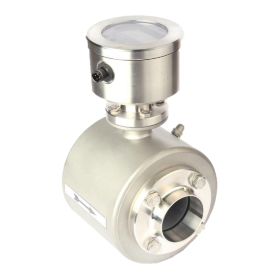
1.2. Function The electromagnetic flow meter, type FMQ, measures both the flow rate and the volume of liquid flows at a high precision. The measuring device is suitable for measuring conductive liquids in principle. -
Page 6: Transmitter In Compact Design
General description Transmitter in compact design Transmitter Compact version Process connection: Aseptic flange Nominal widths: DN 10, 15, 25, 32, 40, 50, 65, 80, 100, 125, 150 Optional product connections: Clamp, dairy pipe, small flange, etc. Meter tube: Material no.: 1.4301 / AISI 304 Liner: Materials:... -
Page 7: Safety Instructions
Safety instructions Safety instructions Due to the great variety of possible conditions of use, this instruction manual can consider the general kind of application only. Special cases such as extraordinary ambient conditions or special safety instructions require coordination with the manufacturer 2.1. -
Page 8: General Safety Instructions
Safety instructions General safety instructions These safety instructions have to be strictly observed in order: • To not endanger the safety of persons and environment • To avoid any damages to the measuring instrument • To prevent any faulty batches upon the production The electric connection may only be carried out by persons who have got the necessary expert knowledge (e.g. -
Page 9: Intended Use
Safety instructions 10. To minimize the danger of injury, the working area of the operator has to allow sufficiently free space. 11. The technical data according to the instruction manual, nameplate and, if available, the performance specification has to be considered. If damage is caused due to an inexpert performance of work any warranty claims will definitely extinguish. -
Page 10: Special Safety Instructions And Devices
Safety instructions 2.3. Special safety instructions and devices The following dangers could be directly or indirectly caused by the flow meter, type FMQ, during operation or commissioning: • Electric shock if the electronic housing is opened improperly • Burns by touching hot pipe sections •... -
Page 11: Transport
Transport Transport 3.1. General information The following points have to be respected in order to avoid damages to the measuring instrument or injuries during the transport of the device: Transport work is only allowed to be carried out: - By accordingly qualified and authorized persons - By the aid of appropriate load suspension and fastening devices Caution - On the condition that any risk can be fully excluded while the device is lifted... -
Page 12: Dimensions And Weight
Transport 3.3. Dimensions and weight Compact version Weight [mm] [mm] [mm] [mm] [mm] [kg] 11.2 13.2 27.0 30.0 - 12 -... -
Page 13: Dimensions Of The Process Connections
Transport Dimensions of the process connections Welding socket (standard) FG hygienic flange Threaded socket DIN 11851 Conical socket / grooved nut DIN 11851 - 13 -... - Page 14 Transport TriClamp DIN 32676 Varivent flange DIN flange EN ISO 1092-1 All undimensioned parts are according to DIN EN 1092-1 PN16, type 11, shape B (DN 10…100) PN10, type 11, shape B (DN 125…150) - 14 -...
-
Page 15: Arrangement
Arrangement Arrangement 4.1. Conditions required for the transmitter In any case the transmitter has to be installed in the product line and the converter has to be supplied with voltage. When selecting the place for the installation of the measuring instrument you should in any rate ensure that the housing can be opened for service work whenever desired and that the flow meter can be simply removed, if necessary. -
Page 16: Fitting Position - Electrode Axis
Arrangement Fitting position – electrode axis Due to the principle described, the fitting position – to a certain extent – can be selected way desired. The basic condition for accurate measuring results is, however, a full and gas-free meter tube. If possible, the electrode axis should be horizontally arranged, in order to avoid a deposition of gas bubbles or solid particles on the surface of the electrodes. - Page 17 Arrangement Suggestions for installation Wrong At the highest point of the pipeline. Gas bubbles → accumulate in the transmitter. Faulty measurement! Wrong Descending pipe: At the end of the conveyance of the metered product → the pipe runs empty. Measuring errors! f reier Auslauf Correct Free outlet...
-
Page 18: Inlet And Outlet Pipe Sections
Arrangement Keep the recommended inlet and outlet sections! 5xD N 3xD N Avoid curvatures of space before the flow meter! Inlet and outlet pipe sections For the installation of electromagnetic transmitters DIN 1944 recommends an inlet pipe section of 5 x DN and, accordingly, an outlet pipe section of 3 x DN in case of an undisturbed flow. -
Page 19: Earthing/Grounding Conditions
4.2. Flow direction The FMQ measures the flows in both flow directions in principle. The main flow direction is marked on the converter by means of an arrow: In the standard setting the digital outputs emit the volume pulses independently of the flow direction. -
Page 20: Conditions Required For The Converter
Arrangement 4.3. Conditions required for the converter Please observe the following points for the locating place to protect the converter against damage: Caution • The limit values for the ambient temperature have to be kept. • Fasten the field housing from mechanical strain! •... -
Page 21: Welding Work
(e.g. welding distortion) is kept limited to the absolute minimum. Before welding work is started, the FMQ will have to be removed from the pipeline: Fasten the FMQ transmitter by some welding point inside the pipeline! -
Page 22: Installation
Installation Installation Only persons disposing of the necessary expert knowledge and authorization of the user are allowed to carry out the installation work. The qualified personnel have to have read and fully understood this instruction manual and follow all instructions given therein. The state of the art is always a decisive criterion for the execution of the installation. -
Page 23: Installation Instructions For The Converter
The following safety precautions have to be followed for the execution of the electrical installation work: The supplying system has to guarantee an overvoltage protection for the device according to category II. For reason of EMC (according to definition EN 50 081-2) the FMQ may be used in industrial areas only. - 23 -... -
Page 24: Dc Input
Installation 5.2.3 DC Input M12-plug connection: 4-pin version 5-pin version M12-plug, 4-pins DC Supply + (24V) 4…20 mA Output DC Supply - (0V / GND) Pulse Output M12-plug, 5-pins DC Supply + (24V) 4…20 mA Output DC Supply - (0V / GND) Pulse Output DC Input + (9…24V) - 24 -... -
Page 25: Digital Input
Installation 5.2.4 Digital Input Digital input Hardware Optocoupler, passive 9…32 V Auxiliary voltage Input resistance < 3.2 kΩ Input frequency 1kHz max. Voltage ON reset counter Function 5.2.5 Digital output Digital output Output current 20 mA max. Voltage drop at the optocoupler at 20 mA 0.5 ... -
Page 26: Display
Installation 5.3 Display The standard version (converter without display) can be retrofitted with a display, if desired. The following parts are required for such a retrofit: Item Description Display Display cable Cover with transparent pane 4x M3x10 Conversion instructions: Unscrew the cover! Connect the display and the converter (plug XD1) by the cable! 3. -
Page 27: Commissioning
Commissioning Commissioning 6.1 General information The measuring device may only be operated by trained persons who have got the necessary authorization from the user of the device. The operators have to be familiar with the process sequence, able to recognize possible dangers, and in a position to take the necessary steps for the removal of accident risks. -
Page 28: Advice For Starting-Up The Fmq
6.3 System structure and operating elements The electronic part is permanently installed in the FMQ converter. The electrical connection (M12 plug) is on the side of the device. The front is equipped with a satin-glass pane with a 3-coloured background LED-lighting. -
Page 29: Zero Point Adjustment ("Zero Adjust")
Metering with an empty meter tube Metrologically perfect flow measurements are only possible, if the meter tube is evidently filled with liquid. In order to avoid an undefined counting in case of an empty meter tube, the FMQ offers an internal possibility for suppression: 6.5.1 "EMPTY pipe detection"... -
Page 30: Status Indication
Malfunction 6.8 Optical operating elements (display version) The display unit is provided with optical keys for the operation which enable the FMQ to be operated through the closed cover. The converter calibrates the optical keys in regular intervals. Such a calibration can only function perfectly, if the optical keys are not covered. -
Page 31: Operation
Operation Only persons disposing of the necessary expert knowledge and authorization of the user are allowed to operate the FMQ. During normal measurements the operation is restricted to the zero reset of the volume registers. The keypad is dynamically controlled by the image navigator. -
Page 32: Basic Keypad Functions
The basic setting of the image navigator is the measured value level where the volume and the flow rate are displayed. A timeout function makes sure that the FMQ always returns to that image level. The image navigator is controlled by the keys Basic functions of the image navigator: •... - Page 33 Operation Main image level Sub-images BE1S1 BE1S2 BE1S3 Measured value Measured value Flow rate Total volume Volume Flow rate Volume BE2S1 BE2S2 BE2S3 BE2S5 Basic parameters Language CS3-Bus Dimensions Q type Device settings BE3S2 BE3S3 Pulse output Device settings BE 4 BE4S1 BE4S2 Digital Input...
- Page 34 GEA Process Engineering CMAG Negele Messtechnik GmbH B7628-00en Operation BE9S1 BE9S2 Info1 Info2 Info3 Image navigator - 34 -...
-
Page 35: Zero Reset Of The Volume Counter
Operation 7.3.1 Zero reset of the volume counter The main image shows the volume. This image is permanently shown while the flow meter is switched on. “Zero reset” is a function which can be carried out without any additional activation. For a zero reset, please keep the key depressed for about 5 seconds. -
Page 36: How To Release A Parameter Change
Operation The next “Dimension” appears on the display. 7.3.4 How to release a parameter change: If a parameter has to be changed and the parameter change is not released, the display will request the input of the code number. Input the code number as described in item 7.2.3. If the correct code number has been input, the display will show the message “Parameter input unlocked”. -
Page 37: Image Level: Measured Values
Operation 7.4 Image level: Measured values The image level consists of the pictures BE1, BE1S1, BE1S2, and BE1S3. 7.4.1 Measured value: Volume key will reset the volume to “0”. A 4-seconds long activation of the The size of the digits is controlled by the size of the measured value. The volume indication is the central image that is always shown after a reset. -
Page 38: Error Message: Transmitter Not Connected
Operation 7.4.5 Error message: Transmitter not connected This error message will be displayed, if the transmitter is not connected. The cause of the error is the missing coil connection. 7.5 Image level: Base parameters The image level consists of the following pictures: BE2, BE2S1, BE2S2, BE2S3, BE2S4 and BE2S5. This image level offers the possibility to make some basic settings. -
Page 39: Dimension
Operation 7.5.3 Dimension key can be used for changing the dimension (unit) of the measured value. You could be asked in advance to enter the unlock code. In case of changing the dimension the single and total amounts will be set back on zero. Abbreviation Unit m dim... -
Page 40: Image Level: Pulse Output
Operation 7.6 Image level: Pulse output The image level consists of the pictures: BE3, BE3S1, BE3S2, and BE3S3. This image level serves for the setting of the pulse output. The main image shows the current device setting. 7.6.1 The pulse value PV1 can be changed by the key. -
Page 41: Image Level: Digital Input
Operation 7.7 Image level: Digital input This image level consists of the pictures BE4, BE4S1, BE4S2. The settings for the digital input are made on this image level. The main image shows the current device setting. 7.7.1 Function: Digital input The function of the digital input can be selected by means of key The input can be set to: •... -
Page 42: Image Level: Current Output
Operation 7.8 Image level: Current output This image level consists of the pictures BE5, BE5S2, and BE5S3. On this image level the settings for the current output are made. The main image shows the current setting of the device. 7.8.1 Qmax The key can be activated for changing the Qmax value for the current output. -
Page 43: Lfs
Operation 7.9.1 The key can be used to change the low-flow suppression LFS in %. The low-flow volume is calculated from the Qmax value. You could be asked in advance to enter the unlock code. 7.9.2 MSPE By means of the key you can change the dimensionless factor MSPE. -
Page 44: Offset
Operation 7.9.5 Offset Press the key for changing the Offset value. The Offset is a calibration value of the sensor which is normally not changed! Code number for the offset level: 145. 7.9.6 SPAN The SPAN value can be changed by the aid of the key. -
Page 45: Zero Adjust
The meter tube has to be filled up with the liquid to be measured. No flow rate is allowed to be available, the liquid rests. Unless the prerequisites are observed, a faulty ZERO value will be determined and the FMQ will not be able work correctly. Important information 7.10.2 Factory settings... -
Page 46: Image Level: Service Level
Operation 7.11 Image level: Service level The image level consists of the pictures BE8, BE8S1, BE8S2, BE8S3, and BE8S4, BE8S5. Only service values are displayed and service functions are performed on this service level. 7.11.1 Error register: Metering This image shows the error numbers of the measurement. The error number is reset while the flow meter is set back to zero. -
Page 47: Simulation Of The Pulse Outputs
You could be asked in advance to enter the unlock code. 7.11.5 Simulation of the flow rate This function can simulate the complete metrological functionality of the FMQ converter, i.e. the pulse outputs and the current output behave like in the normal operation. This function is suitable for the “dry”... -
Page 48: Info2
Unless the device is equipped with a parameter box (standard scope of supply), the text “no parameter box” will be displayed. If the text “SENSORBOX” is displayed, the new box is available particularly for the FMQ. 7.13 LOCK switch From the software version V2.02 it is possible to deactivate the optical keys by means of the LOCK switch (left-hand switch position) in order to avoid operating errors. -
Page 49: Parameterization
Parameterization Parameterization At the factory the FMQ is provided with standard parameters (factory settings). Only trained persons authorized by the user of the flow meter are allowed to set and/or change parameters. The persons concerned have to be familiar with the process sequence. - Page 50 Parameterization Q max [ l/h ] PV1 [ pulse/l ] 3000.0 1000.0 7000.0 100.0 18000.0 100.0 30000.0 100.0 45000.0 10.0 70000.0 10.0 120000.0 10.0 180000.0 10.0 280000.0 10.0 440000.0 640000.0 Table of the abbreviations used and their meaning: Abbreviation Function Pulse value for IMP1 Pulse length for IMP1 Pulse length for IN1...
-
Page 51: Adjustments
Parameterization 8.1 Adjustments The FMQ normally needs no adjustment. Usually, the zero point adjustment (“ZERO adjust”) is carried out during the first commissioning only. If, however, some deviations have to be compensated which were determined e.g. upon a comparison with a calibration vessel or a balance it is possible to make an adjustment via the factor “m spe”. -
Page 52: Adjustment By Calibration Factor "M Spe
The calibration factor is calculated by means of the following formula: Target volume (e.g. calibration vessel, balance, or the like) FMQ display An example is shown overleaf: Example: Deviation F of +0.54% determined during a comparative measurement Calibration vessel:... -
Page 53: Measuring Accuracy
Parameterization 8.2 Measuring accuracy Flow linearity: ± 0.5 % ± 2 mm/s under reference conditions Reproducibility: ± 0.1 % Reference conditions for the determination of the measuring accuracy. According to DIN EN 29104 and VDI/VDE 2641: • Temperature of the measured product: +20°C ±... -
Page 54: Trouble-Shooting
Trouble-shooting Trouble-shooting 9.1 Error diagnosis The FMQ is equipped with an integrated self-monitoring function. Malfunctions are recognized and automatically removed, if necessary. 9.1.1 Error diagnosis via the display Displayed messages can support the troubleshooting in case of malfunction or faulty measurement. -
Page 55: Error List
Trouble-shooting 9.1.2 Error list Error Diagnosis Remedial actions No.: a. The measuring result can be falsified due to the interference received. - Reset the message by resetting the individual quantity to zero! Error found on the occasion of the internal b. -
Page 56: Typical Effects Or Error Sources
Trouble-shooting 9.2 Typical effects or error sources Disturbances or malfunctions can normally be recognized by the aid of the display unit only. 9.2.1 Flow without flow rate indication: (a) Is the conductivity higher than 5 µS/cm? Is the conductivity in case of demineralised water higher than 20 µS/cm? (b) Has the internal EMPTY pipe detection to be switched off? Check whether the display shows “0 L/h”... -
Page 57: No Analog Signal Available
First the connected measuring system (digital display, PLC or the like) has to be completely disconnected from the FMQ. The analog output signal has to be checked by the simulating function by the aid of an ammeter: If the analog output is ZERO at a 50% simulation, the electronic part is defective, i.e. -
Page 58: Deviations Of Measured Values
Trouble-shooting 9.2.4 Deviations of measured values a) Is there a time-related connection between the occurrence of the problem and some modifications to a system in the vicinity of the measuring device? b) Does the deviation show more or less similar values or a constant shift or does it heavily scatter into the positive or negative direction? c) Has something been repaired or replaced? d) Does the deviation always occur at a certain point of time (e.g. -
Page 59: Error Reset
Trouble-shooting Error reset Error messages and error outputs can be reset: By a zero reset of the quantity counter Automatically after a maximum period of 30 seconds, unless any further fault did occur. Transmitter tests 9.4.1 Insulation test The test is carried out by means of an ohmmeter. The meter tube of the transmitter has to be completely emptied before. -
Page 60: Maintenance
• Rinse the pipe system with clear water before the disassembly of fittings or instruments in order to remove possible residuals of chemicals! 10.2 Routine maintenance On normal operating conditions the flow meter type FMQ does not require any special maintenance work. Nevertheless, we wish to give you some recommendations for maintenance steps: Cleaning Deposits in the meter tube or at the electrodes will cause measuring errors or malfunctions. -
Page 61: Preventive Maintenance Steps
• Not to reduce the service life of the system and its components The preventive maintenance steps for the flow meter type FMQ refer to the seals of the pipe connections. The recommended maintenance intervals result from the experience in other systems. However, the... -
Page 62: Repairs
Maintenance Accuracy tests of the measuring instruments of the system in regular intervals in the frame of the in-house quality assurance. Moreover, the measuring instruments should be regularly calibrated at the manufacturer’s workshop. 10.3 Repairs 10.3.1 Sending-in the flow meter to the manufacturer If repairs have to be carried out at the factory, the following conditions will have to be fulfilled in order to enable a quick and cost-effective settlement. -
Page 63: Replacement Of The Sealing Cover Of The Operating Unit
Moreover, it is possible to use those functions for the adjustment and verification of connected devices. 10.4.1 Flow simulation As an adjusting aid or for diagnosing purposes of connected devices the FMQ offers the possibility to simulate flow without any flowing product. 10.4.2 Simulation via the display unit Select the “SIMULATION”... -
Page 64: Decommissioning
Decommissioning Decommissioning 11.1 Temporary decommissioning If the device is to be put out of operation for a temporary period only, no special measures have to be observed for its later recommissioning. If the transmitter is removed from the process line, the pipe system first has to be emptied and depressurized.
Need help?
Do you have a question about the FMQ and is the answer not in the manual?
Questions and answers