
Related Manuals for NXP Semiconductors Freescale TWR-POS-K81


Summary of Contents for NXP Semiconductors Freescale TWR-POS-K81
- Page 1 TWR-POS-K81 Quick Start Guide Development Kit for Point-of-Sale Applications using the Kinetis K81 MCU Tower System Development Platform...
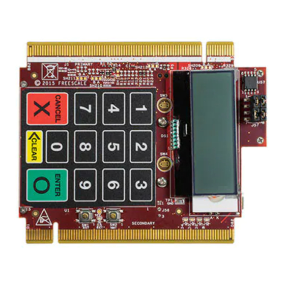
- Page 2 Quick Start Guide Get to Know the TWR-POS-K81 Capacitive Touch PIN Pad Character Segment LCD D1–D4 Reset NMI/PTA4 LEDs Figure 1: Front side of TWR-POS-K81...
- Page 3 freescale.com MK81FN256VDC15 Debug Header Battery Cirque Receptacle SecureSense for VBAT Piezo 512 Mbit Serial Buzzer Flash QuadSPI K81 USB Figure 2: Back side of TWR-POS-K81 TWR-POS-K81 Tower System Development Platform The TWR-POS-K81 development platform is a reference platform for a payment PIN entry device.
- Page 4 Quick Start Guide TWR-POS-K81 Features • MK81FN256VDC15 MCU • Capacitive PIN pad • 2x16 character, dot matrix LCD display 150 MHz ARM Cortex -M4 core, ® ® 256KB Flash, 256 KB SRAM, 121 • Four (4) user-controlled status LEDs XFBGA, with tamper detection and •...
-
Page 5: Configure The Hardware
freescale.com Step-by-Step Installation Instructions In this Quick Start Guide, you will learn how to set up the TWR-POS-K81 board and run the included demonstrated software. Download Software Connect and Tools a Terminal Download and install the KSDK for TWR- Open a terminal emulator program of your POS-K81 software. - Page 6 Quick Start Guide Step-by-Step Installation Instructions (cont.) Configure Enter a the Terminal 4-Digit PIN Setup the terminal for 115200 8-N-1 Use the capacitive PIN pad on the board communication with no flow control: to input any 4-digit value. Press the “Enter” button on the PIN pad when complete.
- Page 7 freescale.com TWR-POS-K81 Jumper Options The following is a list of all the jumper options. The default installed jumper settings are indicated in the shaded boxes. Jumper Option Setting Description Use 5V from USB connector (5V0_K81_USB) Main 5V Power Selection Use 5V supply from elevator (P5V_ELEV) Use 5V from USB connector (5V0_K81_USB) K81 3.3V Regulator Source...
- Page 8 Quick Start Guide TWR-POS-K81 Jumper Options (cont.) Jumper Option Setting Description Tamper 0 and Tamper 2 signals are connected (close active tamper loop) Tamper0-Tamper2 J57, 2-4 Connection Tamper 0 and Tamper 2 signals are disconnected (open active tamper loop) Tamper 5 and Tamper 7 signals are connected (close active tamper loop) Tamper5-Tamper7 J57, 5-7...
- Page 9 freescale.com Virtual COM Port Driver Installation Instructions Find the MSD_CDC_ Choose Device in the Device “Browse...” Manager Click “Update Driver Software…” Then Select “Let me pick…”...
-
Page 10: Driver Location
Quick Start Guide Virtual COM Port Driver Installation Instructions (cont.) Navigate to Your CDC Press Driver Location “Next” <install_dir>\examples\frdmk82f\demo_ apps\usb\device\cdc\virtual_com\inf Ignore the Warning and Press “Yes” NOTE: If you run into driver signature issue on Windows 8, please refer to the link below: https:// learn.sparkfun.com/tutorials/ disabling-driver- signature-onwindows-8/disabling-signed- driverenforcement-on-windows-8. - Page 11 freescale.com...
-
Page 12: Warranty
Support Visit freescale.com/support for a list of phone numbers within your region. Warranty Visit freescale.com/warranty for complete warranty information. For more information, visit freescale.com/TWR-POS-K81, freescale.com/Kinetis freescale.com/Tower Freescale, the Freescale logo and Kinetis are trademarks of Freescale Semiconductor, Inc., Reg. U.S. Pat. & Tm. Off. All other product or service names are the property of their respective owners.
Need help?
Do you have a question about the Freescale TWR-POS-K81 and is the answer not in the manual?
Questions and answers