
Subscribe to Our Youtube Channel
Related Manuals for eta 110


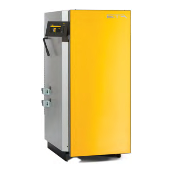
Summary of Contents for eta 110
- Page 1 2020-06-08 0000000109 V.017 110, 218, 121P, 219P 93303-003 Log boiler 20 - 60 kW Installation...
- Page 2 ETA Heiztechnik Gewerbepark 1 A-4716 Hofkirchen an der Trattnach Tel: +43 (0) 7734 / 22 88 -0 Fax: +43 (0) 7734 / 22 88 -22 info@eta.co.at www.eta.co.at...
-
Page 3: Table Of Contents
Contents General ................5 Preface. - Page 4 Dismantling, disposal ..............64 www.eta.co.at...
-
Page 5: General
ETAtouch control system of your ETA boiler. A LAN cable is required for the connection Types of safety instruction from the ETAtouch control system to the internet modem. -
Page 6: Warranty, Guarantee And Liability
8 and 9 customer have installed the heating system partly or entirely without relevant training and in particular The pH value of water used to fill the heating system without up-to-date practical experience, without having must be between 8 and 9. www.eta.co.at... - Page 7 Repair of defects For repairs of defects carried out by the customer or by a third party, ETA shall only bear the costs or remain obligated by warranty if this work was approved in writing in advance by the customer service of ETA Heiztechnik GmbH.
-
Page 8: Technical Data
If the TWIN pellet burner is to be retrofitted, the additional space required for the pellet burner is to be taken into account when setting up the log boiler. Safety heat exchanger R1/2" external threads Return with coupling R5/4" Flow with R5/4" coupling Discharge with R1/2" coupling www.eta.co.at... - Page 9 Technical data Log boiler SH 20-60 kW The flue gas connection on the boiler does not yet give any indication of the required chimney diameter. Information on the required chimney diameter can be found in the installation instructions for the boiler in the Chimney chapter.
-
Page 10: Twin 20-26 Kw
The pellet burner can be delivered for installation on the right or left side. The illustration shows a log boiler (20- 30 kW) with the pellet burner on the left side. Safety heat exchanger R1/2" external threads Discharge with R1/2" coupling Return with coupling R5/4" Flow with R5/4" coupling Pellet suction hose DN50 Pellet return air DN50 www.eta.co.at... -
Page 11: Twin 40-50 Kw
Technical data TWIN 40-50 kW TWIN 40-50 kW TWIN pellet burner 40 - 50 kW dimension sheet The pellet burner can be delivered for installation on the right or left side. The illustration shows a log boiler (32- 60 kW) with the pellet burner on the left side. Safety heat exchanger R1/2"... -
Page 12: Energy Labelling
0.078 0.078 0.078 0.089 load Electrical power consumption at partial load Electrical power consumption in ready mode 0.011 0.008 0.011 0.011 0.011 0.011 Energy efficiency class boiler Energy efficiency index boiler Energy efficiency class "package-system" Energy efficiency index "package-system" www.eta.co.at... - Page 13 Technical data Energy Labelling Log Boiler 20-60 kW Model identification SH 20 SH 30 SH 32 SH 40 SH 50 SH 60 Unit SH 20P SH 30P SH 32P SH 40P SH 50P SH 60P Seasonal space heating energy efficiency mg/m³...
-
Page 14: Regulations, Standards And Guidelines
• EN 13384 "Flue systems - thermal and fluid- dynamic calculation methods" • In Germany, DIN 18160 "Flue systems – planning and design" • In Austria, ÖNORM H 5170 "Heating systems – construction and fire safety requirements". www.eta.co.at... -
Page 15: Ce-Conformity
Heating boilers, Part 1 and 4 We hereby declare that the product in its standard design as stated here corresponds to the above provisions. The technical documentation for this product is administered by ETA Heiztechnik GmbH. Hofkirchen, 31/10/2018 Ing. Johann Eibelhuber... -
Page 16: Boiler Room
[kW] tion from land Requirements for the boiler room ETA) Boiler rooms must be built with fire-resistant F90 (EI90) walls and ceilings; in Switzerland El30 up to 70 kW and EI60 over 70 kW. An escape door to a corridor or to the outside is required. - Page 17 Boiler room In Austria, no more than a week's supply of wood may be stored next to the boiler. For pellets, a separate storeroom EI90 (F90) with a EI30 (T30) door is required. As a result of amendments to building laws, up to 10 tonnes of pellets may be stored in the boiler room in some states.
-
Page 18: Safety
The safety heat exchanger built into the boiler must be with covers for cooling. Never put hot ash into the connected by the heating technician to the house's waste bin! cold water supply via a thermal relief valve to protect www.eta.co.at... - Page 19 Safety Safety devices the boiler against overheating if the pump fails. The The outlet must have an easily visible flow path so mal- minimum pressure in the cold water pipe must be 2 bar functions can be recognised. Direct the discharged and the temperature must not exceed 15 °C.
- Page 20 If the vent pipe ends above a funnel, its discharge pipe must have a cross section at least double that of the valve inlet. www.eta.co.at...
-
Page 21: Information For Installation
Information for installation Chimney Information for installation Chimney 7.1.1 Planning and layout Required chimney diameter Please note that in partial-load operation the exhaust temperature is lower and the large chimney diameters, normally used for solid fuel, are no longer ideal. If the cross section is too large, the flue gas no longer safely rises from the chimney opening and may flow along the roof and sink to the windows of the living quarters. - Page 22 Cold flue gas does not rise from the closes the air flap. This stops combustion. However, as opening; it sinks and can reach living quarters through the combustion chamber temperature doesn't fall, the www.eta.co.at...
- Page 23 Information for installation Chimney wood continues to gasify. Unburned wood gas Connection to the sewage system for the chimney condenses to tar in the chimney, which can be ignited For the condensate in the chimney, a connection to the by sparks from the fire. sewage system (e.g.
-
Page 24: Renovation
From 60 kW boiler output, we recommend using an for heating systems, it should be noted that after a soot deflagration damper. From 100 kW boiler output, an fire the long-term durability cannot be ensured and deflagration damper is required. While the most that www.eta.co.at... -
Page 25: General Information
Information for installation General information penetration of the chimney by moisture cannot be ruled out so that it may be necessary to replace the inner pipe (Criteria for Determination of Suitability and Safe Use of Heating Systems - October 29th 2008, page 12). -
Page 26: Water Hardness
It is cheap and complete desalination with ion exchange cartridges or chemically stable against contamination. In addition, it osmosis is not required. produces a natural alkalinity that generally results in a sufficiently non-corroding pH value of around 8. www.eta.co.at... -
Page 27: Corrosion
Information for installation Corrosion Install a bleed valve at the upper end of the pipe from Lime stabilisation can be dangerous the boiler outlet (already installed in PelletsUnit and The addition of lime stabilising agents prevents PelletsCompact boilers) and also at the highest point in limescale. -
Page 28: Pressure Equalisation
A system separation nitrogen so that it is 0.3 bar higher than the static module with these specifications is available from ETA. pressure at the installation location, but make sure the pressure does not fall below 0.9 bar. - Page 29 Information for installation Pressure equalisation be removed from the valves (hang on the valve with a wire), to ensure that they cannot be closed inadver- tently.
-
Page 30: Buffer Storage Tank
25 litres per kW rated capacity. Hence, a wood chip boiler with 100 kW needs a minimum buffer volume of 2500 l (=100x25). However,pellet boilers up to 70 kW rated thermal input are exempt from this regulation. www.eta.co.at... - Page 31 Buffer storage tank Hydraulic integration With fresh water module With hot water tank Fresh water module flow Boiler flow, heating circuits, oil/gas boiler Boiler flow, heating circuits, hot water tank, oil/gas boiler Temperature sensor [Sensor 1 (upper)] Temperature sensor [Sensor 1 (upper)] Oil/gas boiler return Oil/gas boiler return Temperature sensor [Sensor 2]...
- Page 32 Return for high-temperature circuits 10 Solar return 10 Fresh water module return, solar 11 Return for log boiler, low-temperature circuits 11 Return for log boiler, low-temperature circuits 12 Fresh water module return 12 Temperature sensor [Sensor 3] 13 Temperature sensor [Sensor 4] www.eta.co.at...
-
Page 33: Connection Between Multiple Buffer Storage Tanks
Buffer storage tank Connection between multiple buffer storage tanks Connection between multiple buffer storage tanks Serial connection A serial connection between two buffers has no advantages over a parallel connection; but it does dis- Parallel connection advantages. For example, a suspended hot water tank When there are several buffers, parallel connection can get no heat from the second buffer or an internal (top with top and bottom with bottom) is usually the... - Page 34 > 130 kW er output boiler output maximum 2 maximum 2 buffers buffers external piping with > 80 kW boil- > 130 kW Tichelmann connection er output, boiler output, and/or more and/or more than 2 buf- than 2 buf- fers fers www.eta.co.at...
- Page 35 Buffer storage tank Connection between multiple buffer storage tanks...
-
Page 36: Parallel Buffer Connection
The basic principle of the internal Tichelmann is diagonal flow; Two buffers are connected together at the top and bottom (= parallel connection). For output up to 90 kW, a connection with DN 32 (ETA buffer connection set) is sufficient, for 30 kW use at least R1" or 28 mm copper. On one tank, the boiler outlet is connected at the top; on the other the boiler return is connected at the bottom. - Page 37 Buffer storage tank Parallel buffer connection With fresh water module and stratified charging module Log boiler flow, heating circuits, oil/gas boiler Oil/gas boiler return Load reduction on startup Return for high-temperature circuits Return for log boiler, low-temperature circuits Fresh water module flow Temperature sensor [Sensor 1 (upper)] Solar flow, top Temperature sensor [Sensor 2]...
-
Page 38: External Tichelmann
11 Hot water 12 Cold water Connecting ball valves on buf- maximum total output Collector line at least 30 kW DN 20 DN 25 R 1" 28 x 1.5 60 kW DN 25 DN32 R 1¼" 35 x 1.5 www.eta.co.at... - Page 39 Buffer storage tank External Tichelmann Connecting ball valves on buf- maximum total output Collector line at least 90 kW DN 32 DN 40 R 1½" 42 x 1.5 160 kW DN 32 DN 50 R 2" 54 x 1.5 300 kW DN 40 DN 65 R 2½"...
-
Page 40: Serial Buffer Connection
12 Log boiler, heating circuits return maximum total output Number of buffers Connecting line, minimum 30 kW DN 25 R 1" 28 x 1.5 50 kW DN32 R 1¼" 35 x 1.5 65 kW DN32 R1¼" 35 x 1.5 www.eta.co.at... - Page 41 Buffer storage tank Serial buffer connection maximum total output Number of buffers Connecting line, minimum 80 kW DN 40 R1½" 42 x 1.5 100 kW DN 40 R1½" 42 x 1.5 140 kW DN 50 R2" 54 x 1.5 170 kW DN 50 R2"...
-
Page 42: Installation
SH30 log boiler with the actuators for the air valves on the left side. The illustrations are representative for all compatible ETA log boilers. Fig. 9-1: Side panels Placement of the boiler Loosen the nuts of the air valve shafts on one side of the boiler. -
Page 43: Change Attachment Side
Installation Change attachment side Also take the insulation door off the boiler. The boiler Change attachment side of the insulation door can now be transported into the boiler room. The Remove the pins from the hinges and take the transport dimensions without panels can be found in insulation door off the boiler. - Page 44 Remove panel over the door frame. Guide the cables for the screen (CAN and network connection) to the bracket. Fig. 9-7: Panel Remove the ETAtouch control system screen from the bracket Disconnect the cables (CAN and network connection) from the screen. Fig. 9-8: Screen www.eta.co.at...
- Page 45 Installation Change attachment side Connect the cables for the CAN-Bus and the network Mount panel over the door frame. to the back of the screen. Fig. 9-12: Panel Remove the magnets for the insulation door from the door frame and mount on the opposite side. Fig.
- Page 46 Fig. 9-15: Hinges Suspend the insulation door on the boiler's hinges and secure it with the pins. Fig. 9-17: Replace hinge and closing roller mount Fig. 9-16: Insulation door www.eta.co.at...
- Page 47 Installation Change attachment side For the fuel chamber door, mount the door handle and Hang the doors on the boiler. both pins on the opposite side. Fig. 9-18: Fuel chamber door Close each door to check for tightness. Adjust the For the ignition door, turn the door handle and both hinges and the closing roller mount so that the pins by 180°...
-
Page 48: Draught Fan
Turn both air valve shafts completely until the stop screw. Fig. 9-23: Twist guard Insert the rubber caps on the opposite side so that the air valve shafts cannot be pushed out of the boiler while installing the actuator. www.eta.co.at... -
Page 49: Cleaning Lever
Installation Cleaning lever Push both actuators onto the air valve shafts and boiler. The installation of the automatic heat exchanger secure them with the nuts. cleaner is described in its own manual and is included in the delivery scope of this option. Do not overtighten the nuts;... - Page 50 Loosen the knurled nut on the heat exchanger cover by turning it anti-clockwise and rotate the ball knob by 180°. Fig. 9-27: Knurled nut and ball knob Fig. 9-29: Cleaning lever www.eta.co.at...
- Page 51 Installation Cleaning lever Push the cleaning lever into the turbulator linkage tube Replace the insulation. and secure with the bolts. Fig. 9-32: Insulation Reattach the covers. Fig. 9-30: Bolts Replace the heat exchanger cover. Turn the ball knob clockwise until the stop. Then close the heat Fig.
-
Page 52: Removing Panels
The network cable has already been installed at the factory and is located next to the boiler circuit board. An on-site network extension (1x plug / 1x socket) is Fig. 9-34: Cover required. Lift up and remove the cover over the boiler circuit boards. Fig. 9-35: Cover www.eta.co.at... - Page 53 Installation Network connection...
-
Page 54: 10 Electrical Connections
Potential-free output switching capac- (special function) A single relay output 500 W Maximum line length for temperature sensor The maximum line length for the electrical connection of the temperature sensor is 20 m. Fig. 10-1: Connecting the potential equalisation www.eta.co.at... - Page 55 Electrical connections Requirements Strain relief required for the supply line A strain relief is required for the supply line to the boiler. A strap is available near the cable channels for attachment. Fig. 10-7: Special function - pump (with supply extension 230 Fig.
-
Page 56: Overview Of Circuit Boards
Overview of circuit boards Overview of boiler circuit boards The [MK-E] circuit board is an "extension board" for additional heating circuits. The optional emergency circuit board [NS-A] ensures that the primary air supply to the boiler is closed during a power failure. www.eta.co.at... - Page 57 Electrical connections Overview of circuit boards...
-
Page 58: Circuit Board Sh-C1
Drive of the optional automatic heat ex- 230 V output changer cleaner 230 V output 3 x 1 mm² Boiler pump 230 V output 4 x 1 mm² Start relief 230 V output 4 x 1 mm² Return riser valve www.eta.co.at... - Page 59 Electrical connections Circuit board SH-C1 These terminals can be used (depending on the configuration): Minimum Terminal Function cross-sec- Default assignment tion S91, S585 230 V output Draught fan Potential-free output Malfunction message / diverter valve solar (special function) 24 V AC/DC output / S583 Top actuator Analogue input...
-
Page 60: Circuit Board Gm-C3
S501 T8 Temperature input 2 x 0.5 mm² example, there are three temperature sen- sors on the buffer, then buffer temperature sensor 1 is at the top, buffer sensor 2 in the middle and buffer sensor 3 at the bottom. www.eta.co.at... - Page 61 Electrical connections Circuit board GM-C3 These terminals can be used (depending on the configuration): Minimum Terminal Function cross-sec- Default assignment tion S501 T9 Temperature input 2 x 0.5 mm² Buffer temperature sensor 2 S501 T10 Temperature input 2 x 0.5 mm² Buffer temperature sensor 3 S501 T11 Temperature input...
- Page 62 Circuit board GM-C3 Electrical connections These terminals have already been pre-wired at the factory: Terminal Function Default assignment CAN-Bus supply +24 V (for stand-alone operation) www.eta.co.at...
-
Page 63: 11 Concluding Activities
Concluding activities 11 Concluding activities Mounting the covers Removing protective film Reattach the covers over the boiler circuit boards. Remove protective film from all covers. After longer periods of operation of the boiler, the film can no longer be removed without damaging the paint. Fig. -
Page 64: 12 Dismantling, Disposal
Clean the parts and remove them in accordance with the local regulations for workplace safety and environ- mental protection. Disposal Disposal including all components must be done in an environmentally friendly manner according to waste disposal laws. Recycle any materials that can be recycled. www.eta.co.at... - Page 66 www.eta.co.at...
- Page 68 DOWNLOAD www.eta.co.at...
Need help?
Do you have a question about the 110 and is the answer not in the manual?
Questions and answers