
Related Manuals for eta PE-K 180


Summary of Contents for eta PE-K 180
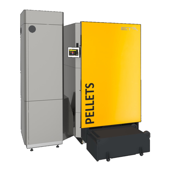
- Page 1 2018-05-24 0000000313 V.005 3.43.0 3308 93222-001 Pellet boiler 180-220 kW Operation...
- Page 2 ETA Heiztechnik Gewerbepark 1 A-4716 Hofkirchen an der Trattnach Tel: +43 (0) 7734 / 22 88 -0 Fax: +43 (0) 7734 / 22 88 -22 info@eta.co.at www.eta.co.at...
-
Page 3: Table Of Contents
Contents General ................5 Preface. - Page 4 10.2 Refilling ............... 86 www.eta.co.at...
-
Page 5: General
General Preface General Preface ETA boiler. A LAN cable is required for the connection from the ETAtouch control system to the internet modem. Dear customer, Details for the remote control can be found in the This user manual provides important information and manual "Communication platform meinETA". -
Page 6: Warranty, Guarantee And Liability
Cleaning and maintaining the product is essential. The from solvents, cleaning agents, adhesives and propel- required steps and intervals are either contained in this lants, or ammonia from cleaning agents, to prevent documentation or included as a separate document. corrosion of the boiler and chimney. www.eta.co.at... - Page 7 Repair of defects For repairs of defects carried out by the customer or by a third party, ETA shall only bear the costs or remain obligated by warranty if this work was approved in writing in advance by the customer service of ETA...
-
Page 8: Boiler Functionality
Boiler functionality Boiler functionality Combustion chamber door Refractory-lined combustion chamber Tilting grate Ash screw under tilting grate Ash bin Ash screw under the turbulators Stoker screw Rotary valve Dosing screw 10 Pellet hopper 11 Fill level sensor www.eta.co.at... - Page 9 Boiler functionality A vacuum turbine sucks the pellets from the storage room, which may be up to 20 m away, into the pellet hopper on the boiler. The pellet hopper has a capacity of up to 215 kg. The dosing screw doses the pellets as they are conveyed from the pellet hopper, in order to avoid overfilling the rotary valve.
-
Page 10: Safety
This action prevents the boiler temperature from rising further and triggering further safety devices such as the safety temperature limiter and the thermal relief valve. www.eta.co.at... - Page 11 Safety Safety devices The heat dissipation is limited by the maximum the supply line from being shut off accidentally, remove flow temperature set in the heating circuits and the levers from ball valves or the hand wheels from the target hot water temperature. valves and hang them there with a piece of wire.
- Page 12 The safety valve discharge (vent) pipe must have at least the same nominal diameter as the valve outlet, have a consistent downhill gradient and be routed to a sewer connection. The vent pipe may contain a maximum of 2 bends and be 2 m long. If www.eta.co.at...
-
Page 13: Empty The Ash Bins
Empty the ash bins Empty the ash bins Stop heating To remove the ash bins, pull the lever on the side towards the ash bins to release them. Remove the ash End the boiler's heating mode with the On/Off switch bins from the boiler. - Page 14 Fig. 4-5: Seal Attach the ash bins to the boiler Reattach the cover to the ash bins and secure with the fasteners. Then re-open the covers in the lids. Fig. 4-6: Covers www.eta.co.at...
-
Page 15: Etatouch Controller
ETAtouch controller Getting to know the control system ETAtouch controller Getting to know the control listed in the uppermost row on the screen. The respective user interface is opened with a single tap of system the finger. Get to know the control system Take your time and read the following chapter carefully. -
Page 16: User Interface
For the heating circuit, for example, the heating times and the heating curve are adjusted here. Graphic display of the heating times and room tem- peratures settings Different operating modes of the heating circuit www.eta.co.at... -
Page 17: Text Menu
ETAtouch controller Getting to know the control system 5.1.2 Text menu Resetting to factory settings is done by pressing the [Factory settings] button. To cancel and close the window, tap the arrow on the left side of the screen. Adjust parameters in the text menu Only modify parameters whose function you're To enter the text menu, tap in the upper left on the familiar with. -
Page 18: Messages
Other errors and alarms can only be ac- knowledged after the cause has successfully been To disable help, press the button again. remedied. Once an error or alarm has been resolved and acknowledged, you must restart the boiler or the affected function block. www.eta.co.at... -
Page 19: Inputs And Outputs
ETAtouch controller Getting to know the control system If the error symbol at the bottom of the screen is When authorization is given, the terminal tapped, a window appears. In this, the function block in assignment can be changed. Also, manual mode which the error occurred will be displayed. -
Page 20: Getting Started
The date and time are factory-set to Central European Time (UTC+01:00). For setting on the screen, tap the date or time. A settings window appears. Fig. 5-15: System configuration menu To close the system settings, simply tap the symbol again. Fig. 5-17: Date and time www.eta.co.at... - Page 21 ETAtouch controller Getting to know the control system Using the arrow keys, set the time. Tap on the date To change the name, tap on the [Change name] field to open the calendar. Press the [Save] button to symbol. An on-screen keyboard appears in order to save.
- Page 22 In some function blocks, the time window for charging the tank (for example the buffer and hot water tank), or the operating times (for example for the heating circuit) are set. This time window must be created in the settings of the respective function block. www.eta.co.at...
- Page 23 ETAtouch controller Getting to know the control system 3. An overview screen opens. Setting the charging times 1. In the overview, select the charge time. In each field, use the arrow keys ( ) to set the time and temperature. Fig.
- Page 24 3. Now, select the days of the week for which the time window is to be copied. In this example Saturday and Sunday. Fig. 5-30: Select days of the week Pressing the [Mark all days] button marks all days. www.eta.co.at...
-
Page 25: Meineta Remote Control
If there via the in-house power grid. This dLAN adapter is also is no connection, one must be established. available from ETA. Enter the login information and the identification plate number of the boiler (if this is not displayed) in the relevant fields. -
Page 26: Favourites
You can change the options at any time by pressing the remote control symbol at the bottom of the screen. Fig. 5-36: Editing a favourite group The name is changed with the [Rename group ] button and the group deleted with the [Delete group ] button. www.eta.co.at... - Page 27 ETAtouch controller Getting to know the control system Parameters already added are adapted with the The overview of the favourite groups appears. With the [Edit parameter ] button. Their sequence button choose any group to which you want to add display is changed with the arrow keys.
-
Page 28: Usb Camera
2. Open the system settings and change to the [Camera] menu. Then in the newly opened window tap on the [USB cable] button. 3. The button starts and stops the transmission of the camera image. Fig. 5-43: Displaying a camera image www.eta.co.at... - Page 29 ETAtouch controller Getting to know the control system...
-
Page 30: Boiler] Function Block - Pe-K
If the amount of pellets in the pellet bin drops below sweeping of the chimney can be selected. The boiler the minimum, the suction turbine starts and refills will then start in time to reach the operating the pellet bin. Return temperature 10 Producer for the boiler (pellet store) www.eta.co.at... -
Page 31: Text Menu - Adjustable Parameters
The de-ashing interval may only be modified after consultation with a specialist or ETA customer Settings menu service. In the settings menu ( [Settings] button in the overview), the following functions and parameters can Explanation of [De-ash after min.] and [De-ash... -
Page 32: Bufferflex] Function Block
For this reason, it is advisable to set generous charging times. A solar heating system connected to the buffer can charge it at any time, regardless of the set buffer charging times. www.eta.co.at... -
Page 33: Setting The Buffer Charging Times
ETAtouch controller [BufferFlex] function block 5.3.1 Setting the buffer charging times When the buffer is the only heat producer in the heating system, the buffer charging times also indirectly determine the operating hours of the boiler. Open the overview of the charging times set Because it can only switch to heating mode within the The operating hours of the buffer can be adjusted in buffer charging periods. -
Page 34: Setting Warnings
Fig. 5-50: Stratified charging of the buffer In the "BufferFlex" text menu, different settings for the [Solar storage strategy] parameter are possible (see chapter 5.3.5 "Text menu - Adjustable parameters", parameter [Solar storage strategy]) for stratified charging of the buffer by the solar heating system. www.eta.co.at... -
Page 35: Buffer As A Combination Tank
ETAtouch controller [BufferFlex] function block 5.3.4 Buffer as a combination tank 5.3.4.1 Setting the hot water charging times Opening charging times and temperature for hot "BufferFlex" with integrated hot water tank or coils water with a combination tank The current hot water temperature is shown at the top The charging times for the hot water and the set tem- of the screen by the water tap icon. -
Page 36: Text Menu - Adjustable Parameters
End solar prio. all components of the heating system are controlled by Min. out. temp. Solar prio. the ETA control system. A higher value is required if peaks in output have to be covered or very fast heat Consumers availability is needed. - Page 37 ETAtouch controller [BufferFlex] function block The value should be at least 5 - 10 °C above the Explanation of [Buffer max] average return temperature of the consumers, This configurable shutdown temperature sets a but no more than 70 °C. A high shutdown temperature threshold for how much the buffer can be charged by reduces the number of boiler starts and improves the solar heating system, to prevent the buffer from...
- Page 38 Optional: only for circulation pump This parameter specifies the duration for operating the circulation pump after it has been started by the control system. Once this time has expired, the circulation pump is switched off for the set duration [Circulation pause]. www.eta.co.at...
- Page 39 ETAtouch controller [BufferFlex] function block...
-
Page 40: Buffer] Function Block
Currently, the consumers are charged with a flow Because it can only switch to heating mode within the temperature of 64 °C. buffer charging periods. [Settings] button. In this menu, the charge times are set. www.eta.co.at... -
Page 41: Setting The Buffer Charging Times
ETAtouch controller [Buffer] function block 5.4.1 Setting the buffer charging times 5.4.2 Buffer with solar heating system Open the overview of the charging times set Buffer with solar heating system The operating hours of the buffer can be adjusted in The control principles of the solar heating system the settings ( button). -
Page 42: Buffer As A Combination Tank
Opening charging times and temperature for hot water with a combination tank The charging times for the hot water and the set tem- peratures can be adjusted in the settings ( button). To adjust, open the settings and then open the www.eta.co.at... - Page 43 ETAtouch controller [Buffer] function block charging times of any given day with the [Hot water Charging times Daily plan] button. An overview screen opens. Fig. 5-57: Overview Set time window (charging times) Select day of the week Add another time window Graphical representation of the time window setting Overview of all time windows for the entire week...
-
Page 44: Text Menu - Adjustable Parameters
The factory setting can remain unchanged as long as all components of the heating system are controlled by the ETA control system. A higher value is required if Buffer bottom Solar peaks in output have to be covered or very fast heat Buffer bottom max availability is needed. - Page 45 ETAtouch controller [Buffer] function block Explanation of the [Extra charge] function Explanation of [Min. out. temp. Solar prio.] This function defines a daily point in time for the buffer This parameter sets the minimum value for the outside (=[Start time]) to charge the buffer additionally. This temperature, so that one of the conditions for solar charging is done independently of the actual consumer priority and stratified charging of the buffer storage...
- Page 46 With a combination tank, this value can be set to approximately 5°C to 8°C if the amount of hot water is insufficient. Explanation [Circulation runtime] Optional: only for circulation pump www.eta.co.at...
- Page 47 ETAtouch controller [Buffer] function block...
-
Page 48: Hot Water Tank] Function Block
When active, the button is highlighted in yellow Mode of operation In the settings menu ( button), the time window for charging the hot water and the desired hot water temperature can be set. See chapter 5.5.1 "Setting the hot water charging times". www.eta.co.at... -
Page 49: Setting The Hot Water Charging Times
ETAtouch controller [Hot water tank] function block 5.5.1 Setting the hot water charging times 5.5.2 Text menu - Adjustable parameters Open the overview screen of the set charging Commonly used parameters can be found in the times and temperatures settings The charging times for the hot water and the set tem- Commonly used parameters can be found in the peratures can be adjusted in the settings (... - Page 50 (e.g. by sink, shower ...), because otherwise an incorrect time is measured. Explanation [Circulation pause] Optional: only for circulation pump This parameter sets the pause after a circulation pump operation. The control system can only restart the circulation pump after this pause/break has expired. www.eta.co.at...
- Page 51 ETAtouch controller [Hot water tank] function block...
-
Page 52: Fresh Water Module] Function Block
To do this, the "self-learning" function must be switched off (= parameter [Self-learning] to [No]). The operating times of the circulation pump are now set manually, for example from 10:00 am to 2:00 pm . Within these time windows, the circulation pump alternately starts and pauses, www.eta.co.at... -
Page 53: Setting The Hot Water Charging Times
ETAtouch controller [Fresh water module] function block 5.6.1 Setting the hot water charging times based on the set runtimes and pauses, regardless of whether hot water is currently being drawn or not. Open the overview screen of the set charging Example: times and temperatures Time window = 10:00 am to 2:00 pm... -
Page 54: Text Menu - Adjustable Parameters
This function is also called the "Auto Loop" parameter [Circulation runtime]. function. This function is set to [Yes] by default. If [No] is set, the operating times for the circulation pump can be set manually. Explanation [Circulation runtime] Optional: only for circulation pump www.eta.co.at... - Page 55 ETAtouch controller [Fresh water module] function block...
-
Page 56: Heating Circuit] Function Block
This means that the room sensor only regulates to the set reduced room temperature [Set-back temperature outside the time window]. Without a room sensor, the heating circuit is controlled with the heating curve for the reduced operation mode. www.eta.co.at... -
Page 57: Operating Elements
ETAtouch controller [Heating circuit] function block Switching between heating and reduced operation In reduced operation mode, a reduction by 1 °C takes place automatically when the button is used causes the reduced temperature for all days of the in the user interface to select the [Timer] operating week to decrease correspondingly. -
Page 58: Setting The Heating Time Slots
Setting absent time (holiday function) In each heating circuit, a time frame can be defined for reduced operation mode. The heating circuit is then operated with the lowest set-back temperature. This function is also called the holiday function. www.eta.co.at... -
Page 59: The Heating Curve
(blue line) Heating limit for reduced-temperature mode Parameters for setting the heating curve and the If an ETA room sensor is installed for the heating heating limits circuit, the flow temperature calculated on the Change settings for the heating curve in heating basis of the heating curve is corrected. - Page 60 ETA room sensor If the rooms are not warming up, you should check the • If a room is too cold, check the room sensor, or in following points first before changing the heating curve the control system set the operating mode and the in the control system.
- Page 61 Explore this in con- efficient. sultation with your heating contractor or ETA customer service. At outdoor temperatures above freezing, the rooms are always too hot or too cold: 1.
- Page 62 Fig. 5-72: Heating threshold for heating mode With underfloor heating, reduced operation mode is only partially noticeable because this heating system reacts very slowly due to the high thermal mass of the screed. Changes in parameters [Set-back difference] are therefore often not noticeable. www.eta.co.at...
-
Page 63: Text Menu - Adjustable Parameters
ETAtouch controller [Heating circuit] function block 5.7.4 Text menu - Adjustable parameters Setting heating limits for the reduced operation mode 1. Change the selector switch to the reduced Adjustable parameters operation mode position ( Heating circuit Use the arrow keys to reduce parameter [Heating Room threshold], so that the heating circuit in reduced Room effect... -
Page 64: Solar] Function Block
The solar heating system control principle water tank 60 °C), or if the collector is only warmer by The ETA control principle for solar heating systems is the offset [Switch-off diff.] (factory setting 5 °C) than defined so that an adjustable temperature difference the tank, the collector pump is switched off. -
Page 65: Solar Heating System With 2 Tanks
ETAtouch controller [Solar] function block 5.8.2 Solar heating system with 2 tanks 5.8.3 Solar heating system for buffer with 2 internal coils Switching between several tanks Switching between two internal coils If the solar heating system charges several tanks (for example, buffer and hot water tanks) it will switch When switching between two internal coils, charging is between tanks on the basis of the currently set... - Page 66 (for charging the buffer). • [Optimise yield]: The solar heating system will begin to charge the buffer as soon as the collector temperature is greater than the current buffer temperature. www.eta.co.at...
-
Page 67: Solar Heating System With External Heat Exchanger
ETAtouch controller [Solar] function block 5.8.4 Solar heating system with external solar heating systems with external heat exchangers, experience has shown that most of the heat exchanger energy from the solar heating system goes to the tank in this control principle. Solar heating system with external heat exchanger The control principle is the same as in a solar heating system with just one tank, see chapter... -
Page 68: Solar Heating System With External Heat Exchanger And Stratified Charging Valve
The working is again charged. temperature of the solar panel is therefore lower, but The secondary flow temperature rises when the there are fewer losses via the solar panel. collector temperature increases or the speed of the secondary pump decreases. www.eta.co.at... - Page 69 ETAtouch controller [Solar] function block...
-
Page 70: Aux.boiler] Function Block
In heating systems with a buffer, the burner is only put into operation if the buffer requests a capacity that is higher than that of the ETA heating boiler. For heating systems without a buffer, the burner is only put into operation when the ETA heating boiler does not reach the required output. -
Page 71: Setting The Charging Times
The standby times of the burner can be adjusted in the If there is still a demand by the ETA control system settings ( button). To adjust, open the settings and after this period ends, then the auxiliary boiler will then open the standby times of any given day with the begin operation. -
Page 72: External Heat Demand] Function Block
ETA heating system. [GM-C2] circuit board, the output or temperature required by the heat consumer can be communicated to the ETA control system via an analogue signal (0-10 V or 4-20 mA). Operating condition and information. -
Page 73: Setting The Charging Times
ETAtouch controller [External heat demand] function block 5.10.1 Setting the charging times Explanation of [Enable temperature] This parameter is used to set the minimum Open the overview screen of the set charging temperature of the heating system for starting the times and temperatures charging pump of the external heat consumer. -
Page 74: Heating Pipeline] Function Block
If the outside temperature drops below the set frost protection limit (factory set at -20 °C), the remote pump remains in operation until the outdoor temperature is at least 2 °C higher than the set temperature [Frost pro- tection]. www.eta.co.at... -
Page 75: Pellet Store] Function Block
ETAtouch controller [Pellet store] function block 5.12 [Pellet store] function block Pellet store overview screen Operating condition and information. A description of the operating conditions can be found in the integrated Help menu by pressing the button. Current pellet stock. This is calculated by the control system and can therefore differ by +/- 15% from the actual pellet supply... -
Page 76: Pellet Store With Switch Unit] Function Block
This button manually switches to the next operations of an enabled suction head. When a enabled suction probe, in order to move the suction head has reached this number, the switch unit pellets. automatically changes to the next enabled suction head. www.eta.co.at... -
Page 77: Rectifying Problems
Rectifying problems Rectifying problems Ash screw jammed WARNING! If the ash screw is stuck, a corresponding warning will Danger of crushing due to tilting grate be displayed on the screen. When the grate is tilted, switch off the boiler with The most common cause of a blockage is a full the mains switch. - Page 78 5. Then insert the ash screw again and secure it with the M8 screw. Replace the ash box and switch on the boiler with the mains switch. To perfom the check, start de-ashing by pressing the [De-ash] button. Switch the boiler back on with the On/Off switch. www.eta.co.at...
-
Page 79: Information On Fuel
Information on fuel Information on fuel When the fuel causes slag If pieces of slag are found in the ash box, the cause often lies in the flue gas recirculation. For this reason, clean and check the flue gas recirculation. An excessive flue draught can also cause slag by reducing the effectiveness of the flue gas recirculation. -
Page 80: Emission Measurement
In spring and fall, the consumers in the heating system usually need less heat. If emissions are PE-K 105-140 1:40 h measured during this time, excess heat cannot be PE-K 180-220 2:00 h safely removed from the heating system. As a remedy, Log boiler 1:30 h temporarily switch the heating circuits to continuous "Day"... -
Page 81: Adjustable Parameters
Emission measurement Information about measurement Long horizontal flue pipes to the chimney must have a Cleaning aperture in the connecting pipe narrow diameter and above-average insulation (>50 Easily accessible cleaning apertures must be available mm). Provide enough cleaning apertures in the flue for cleaning the flue pipe. -
Page 82: Perform Emissions Measurement
The boiler will then start in time to reach the permissible operating temperature for measurement purposes. Fig. 8-4: Set date 4. If the boiler is ready for emissions measurement, a corresponding message will appear on the screen. In addition, a countdown for the emissions www.eta.co.at... - Page 83 Emission measurement Perform emissions measurement measurement will be displayed. The emissions measurement is to be carried out during this period. The measurement takes about 2 to 3 hours. Fig. 8-5: Countdown In this time the boiler is operated at full load (or partial load respectively)
-
Page 84: Low-Emission Operation
It was determined under laboratory conditions in changes made to sections 20 and 21 of the Clean Air testing centres that the ETA boiler complies with the Act 1993 by section 15 of the Deregulation Act 2015. new limit values. To be fair, however, it should be noted... -
Page 85: 10 Heating Water
Heating water Water hardness 10 Heating water 10.1 Water hardness Determine permissible water hardness for the heating water according to ÖNORM H 5195-1 Table 1 Table 2 Heat producer with large (> 0.3 l/ Heat producer with small (> 0.3 l/ kW) water content kW) water content ≥... -
Page 86: Refilling
(below 10% the system volume), then normal tap water can be used. This applies, for example, when replacing a pump or mixer. The heating system is never to be refilled with rainwater, as this is usually contaminated and the pH value is too low. www.eta.co.at... - Page 88 DOWNLOAD www.eta.co.at...
Need help?
Do you have a question about the PE-K 180 and is the answer not in the manual?
Questions and answers