Sign In
Upload
Download
Table of Contents
Contents
Add to my manuals
Delete from my manuals
Share
URL of this page:
HTML Link:
Bookmark this page
Add
Manual will be automatically added to "My Manuals"
Print this page
×
Bookmark added
×
Added to my manuals
Manuals
Brands
eta Manuals
Boiler
VR 250
Installation manual
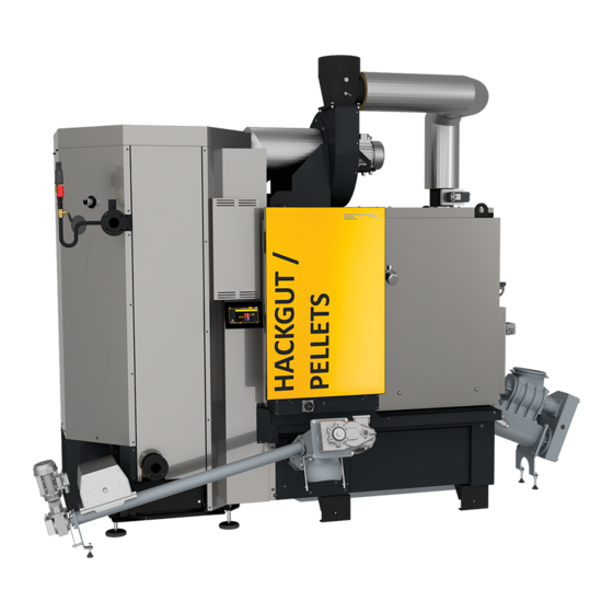
eta VR 250 Installation Manual
Moving-grate boiler 250 kw
Hide thumbs
1
2
Table Of Contents
3
4
5
6
7
8
9
10
11
12
13
14
15
16
17
18
19
20
21
22
23
24
25
26
27
28
29
30
31
32
33
34
35
36
37
38
39
40
41
42
43
44
45
46
47
48
49
50
51
52
53
54
55
56
57
58
59
60
61
62
63
64
65
66
67
68
69
70
71
72
page
of
72
Go
/
72
Contents
Table of Contents
Bookmarks
Table of Contents
Table of Contents
1 General
Preface
General Information
Warranty, Guarantee and Liability
Dismantling, Disposal
2 Technical Data
Boiler
Ashing System
Energy Labelling
3 Regulations, Standards and Guidelines
4 CE-Conformity
5 Boiler Room
6 Safety
General Information
Safety Devices
Emergency Stop Switch
Safety Devices in the Fuel Path
7 Information for Installation
Chimney
Planning and Layout
Renovation
General Information
Water Hardness
Bleeding
Corrosion
Pressure Equalisation
8 Buffer Storage Tank
General Information
9 Installation
Preparing the Heat Exchanger
Preparing the Combustion Chamber
Grate Ash Screw
Connecting the Combustion Chamber and Heat Exchanger
Piping between the Combustion Chamber and the Heat Exchanger
Draught Fan and Flue Connection
Flue Gas Recirculation Piping
Cross Ash Screw
Heat Exchanger Ash Screws
Ignition Fans
Temperature Sensors
Installing Safety Devices
Fuel Conveyor
External Ash Removal
Ashing with Downpipe
Ashing with Ash Flap
10 Electrical Connections
11 Fuel Store
Requirements
Dimensioning
Tilted Floor
Pellet Operation
Heating Value
Technical Data
Advertisement
Quick Links
1
Boiler
2
Technical Data
Download this manual
2020-12-17
EN
0000000421
V.005
3400
939054-001
Moving-grate boiler
250 kW
Installation
Table of
Contents
Previous
Page
Next
Page
1
2
3
4
5
Advertisement
Table of Contents
Need help?
Do you have a question about the VR 250 and is the answer not in the manual?
Ask a question
Questions and answers
Related Manuals for eta VR 250
Boiler eta VR 350 Installation Manual
Moving-grate boiler 250 kw (72 pages)
Boiler eta VR 500 Installation Manual
Moving-grate boiler 250 kw (72 pages)
Boiler eta eHACK 180 Installation Manual
Wood chip boiler (84 pages)
Boiler eta HACK Installation Manual
Replacing the combustion chamber 20 - 140 kw (12 pages)
Boiler eta eHACK 20-50 kW Service Manual
Wood chip boiler (76 pages)
Boiler eta HACK 350 Service Manual
Moving-grate boiler, size 2 (76 pages)
Boiler eta SH20 Operation
Log boiler 20 - 60 kw (80 pages)
Boiler ETA SH Installation Manual
Log boiler 20-60 kw (52 pages)
Boiler eta eHACK 60 Installation Manual
Wood chip boiler (88 pages)
Boiler eta HACK 20 Operation
Wood chip boiler 20-90 kw (92 pages)
Boiler eta PE-K User Manual
Pellet boiler 35 to 90 kw (76 pages)
Boiler eta PE-K 35 Installation Manual
Pellet boiler (60 pages)
Boiler eta Hack 200 kW Service Manual
Wood chip boiler (68 pages)
Boiler eta PelletsUnit Operation Manual
7-15 kw (76 pages)
Boiler ETA PelletsCompact Series Operation
20 to 32 kw (64 pages)
Boiler eta Pellets Compact Service Manual
(36 pages)
This manual is also suitable for:
Vr 333
Vr 350
Vr 463
Vr 500
13250
13333
...
Show all
13350
13463
13500
Table of Contents
Print
Rename the bookmark
Delete bookmark?
Delete from my manuals?
Login
Sign In
OR
Sign in with Facebook
Sign in with Google
Upload manual
Upload from disk
Upload from URL


Need help?
Do you have a question about the VR 250 and is the answer not in the manual?
Questions and answers