
Subscribe to Our Youtube Channel
Related Manuals for eta 13180 LP-D


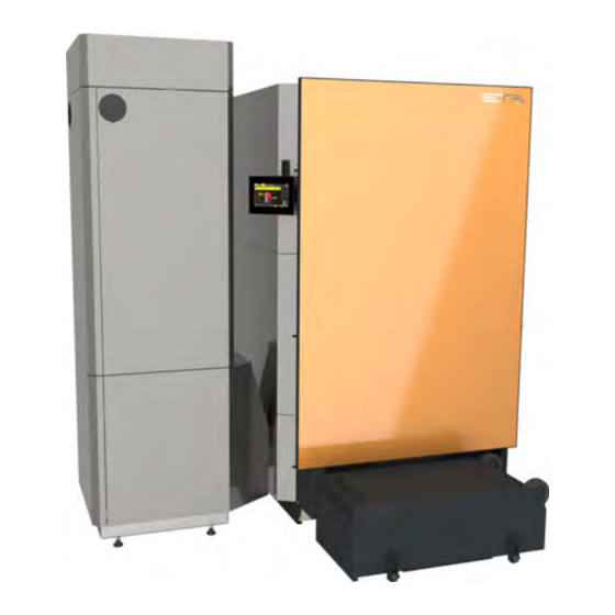
Summary of Contents for eta 13180 LP-D
- Page 1 2020-04-21 0000000475 V.006 5402, 00 939091-002 Pellet boiler ePE-K 180-240 kW Installation...
- Page 2 ETA Heiztechnik Gewerbepark 1 A-4716 Hofkirchen an der Trattnach Tel: +43 (0) 7734 / 22 88 -0 Fax: +43 (0) 7734 / 22 88 -22 info@eta.co.at www.eta.co.at...
-
Page 3: Table Of Contents
Contents General ................5 Preface. - Page 4 13.9 Fire safety regulations ............83 www.eta.co.at...
-
Page 5: General
ETAtouch control system of your ETA boiler. A LAN cable is required for the connection Types of safety instruction from the ETAtouch control system to the internet modem. -
Page 6: Warranty, Guarantee And Liability
"Water hardness". and the relevant rules and safety regulations. If you as customer have installed the heating system partly or entirely without relevant training and in particular without up-to-date practical experience, without having www.eta.co.at... - Page 7 Repair of defects For repairs of defects carried out by the customer or by a third party, ETA shall only bear the costs or remain obligated by warranty if this work was approved in writing in advance by the customer service of ETA Heiztechnik GmbH.
-
Page 8: Technical Data
For maintenance on the boiler, an area which is to be kept clear is required on the side of the boiler on which the pellet module is mounted. No expansion tanks or other devices may be installed within the maintenance area. www.eta.co.at... - Page 9 Technical data The flue gas connection on the boiler does not yet give any indication of the required chimney diameter. Information on the required chimney diameter can be found in the installation instructions for the boiler in the Chimney chapter. Pellet boiler Unit 53.9 -...
-
Page 10: Energy Labelling
0.078 0.358 0.078 0.358 0.078 0.358 0.078 0.358 load Electrical power consumption in ready 0.017 0.017 0.017 0.017 0.017 0.017 0.017 0.017 mode Seasonal space heating energy effi- ciency Seasonal space heating emissions - mg/m³ <40 <40 <40 <40 <40 <40 <40 <40 dust (10% O www.eta.co.at... - Page 11 Technical data Energy Labelling Pellet boiler ePE-K 180-240 kW Model identification Unit 180EP 200EP 220EP 240EP Seasonal space heating emissions - mg/m³ <20 <20 <20 <20 <20 <20 <20 <20 (10% O Seasonal space heating emissions - mg/m³ <500 <500 <500 <500 <500...
-
Page 12: Regulations, Standards And Guidelines
• EN 12831 "Heating systems in buildings - method for calculating standard heating load" • EN 13384 "Flue systems - thermal and fluid- dynamic calculation methods" • In Germany, DIN 18160 "Flue systems – planning and design" www.eta.co.at... -
Page 13: Ce-Conformity
Heating boilers, Part 1 and 4 We hereby declare that the product in its standard design as stated here corresponds to the above provisions. The technical documentation for this product is administered by ETA Heiztechnik GmbH. Hofkirchen, 04.03.2020 Ing. Johann Eibelhuber... -
Page 14: Boiler Room
[kW] tion from land Requirements for the boiler room ETA) Boiler rooms must be built with fire-resistant F90 (EI90) walls and ceilings; in Switzerland El30 up to 70 kW and EI60 over 70 kW. An escape door to a corridor or to the outside is required. -
Page 15: Safety
Safety General information Safety General information Storage of ash The ash must be kept in non-flammable containers with covers for cooling. Never put hot ash into the Operation only by trained personnel waste bin! The product may be operated by trained adults only. Training may be provided by the heating technician or our customer service. - Page 16 Every heat producer in a heating system must be protected by at least one safety valve against pressure exceeding the maximum permissible operating pressure (see EN 12828). These valves must be designed such as to ensure the maximum www.eta.co.at...
- Page 17 Safety Safety devices permissible operating pressure that can arise in the The safety valve may be installed in any position, but heating system or parts thereof. The safety valve must the upper part of the valve must not face downward. be situated in the boiler room and be easily accessible.
-
Page 18: Information For Installation
The better the boiler and the chimney are matched, the dimensions and suitability of existing chimneys greater the energy with which the flue gas exits the especially before boiler installation. chimney, and therefore the certainty that it will rise up into the air. www.eta.co.at... - Page 19 Information for installation Chimney If the diameter is too large, the chimney will not be Obsolete regulations stipulate the wrong chimney heated sufficiently, exit velocity Laws and regulations demand a moisture-resistant temperature will be too low. The flue gas then lacks the flue system for oil and gas and one that is resistant to energy to rise and, in extreme cases, the smoke can soot fires for solid fuels.
- Page 20 Fig. 7-1: Draught limiter Flue gas recirculation conveys a portion of the flue gas back to the boiler to cool the combustion chamber. An overly strong flue draught prevents the recirculation to the boiler and the flue gas reaches the www.eta.co.at...
- Page 21 Information for installation Chimney Connection to the sewage system for the chimney Cleaning aperture in the connecting pipe For the condensate in the chimney, a connection to the Easily accessible cleaning apertures must be available sewage system (e.g. duct) with at least DN25 via a for cleaning the flue pipe.
-
Page 22: Renovation
German Association of Chimney Sweeps has found the following solution to the standards and regulations dilemma: "in the certification of suitability and safe use for heating systems, it should be noted that after a soot fire the long-term durability cannot be ensured and www.eta.co.at... -
Page 23: Water Hardness
Information for installation Water hardness Water hardness Determine permissible water hardness for the heating water according to ÖNORM H 5195-1 Table 1 Table 2 Heat producer with large (> 0.3 l/ Heat producer with small (> 0.3 l/ kW) water content kW) water content ≥... -
Page 24: Corrosion
For boilers of the eHACK series, a separate connection is available on the boiler for the safety valve, pressure gauge and bleed valve. The piping to the safety valve and the bleed valve must be www.eta.co.at... -
Page 25: Pressure Equalisation
A system separation nitrogen so that it is 0.3 bar higher than the static module with these specifications is available from ETA. pressure at the installation location, but make sure the pressure does not fall below 0.9 bar. -
Page 26: Noise Emission
In normal operation, the airborne noise emissions from ETA sound-insulation set. Design the rigidly a pellet or wood chip boiler is between 40 and 50 dB(a) connected installation (flow and return, thermal... -
Page 27: Buffer Storage Tank
Buffer storage tank General information Buffer storage tank General information Choosing buffer size for systems with automatic fuel supply Even if some subsidy guidelines demand "litres per Finely adjustable radiator valves and fresh water kilowatt" and thereby specify a minimum buffer size, module one should arrange for a technically correct size. -
Page 28: Hydraulic Integration
In all cases, an oil or gas boiler should be connected at the top part of the buffer only. Siphon loops downwards at all connections reduce heat losses in summer. www.eta.co.at... - Page 29 Buffer storage tank Hydraulic integration With hot water tank With fresh water module Fresh water module flow Boiler flow, heating circuits, hot water tank, oil/gas Boiler, heating circuits, oil/gas boiler flow boiler Temperature sensor [Sensor 1 (upper)] Temperature sensor [Sensor 1 (upper)] Oil/gas boiler return Oil/gas boiler return Temperature sensor [Sensor 2]...
- Page 30 Boiler, high-temperature circuit return Solar flow, lower Temperature sensor [Sensor 4] Boiler, high-temperature circuit return 10 Solar return 10 Temperature sensor [Sensor 4] 11 Fresh water module return 11 Fresh water module return, solar 12 Low-temperature circuits return 12 Low-temperature circuits return www.eta.co.at...
-
Page 31: Connection Between Multiple Buffer Storage Tanks
Buffer storage tank Connection between multiple buffer storage tanks Connection between multiple buffer storage tanks Serial connection A serial connection between two buffers has no advantages over a parallel connection; but it does dis- Parallel connection advantages. For example, a suspended hot water tank When there are several buffers, parallel connection can get no heat from the second buffer or an internal (top with top and bottom with bottom) is usually the... - Page 32 > 130 kW er output boiler output maximum 2 maximum 2 buffers buffers external piping with > 80 kW boil- > 130 kW Tichelmann connection er output, boiler output, and/or more and/or more than 2 buf- than 2 buf- fers fers www.eta.co.at...
- Page 33 Buffer storage tank Connection between multiple buffer storage tanks...
-
Page 34: Parallel Buffer Connection
The basic principle of the internal Tichelmann is diagonal flow; Two buffers are connected together at the top and bottom (= parallel connection). For output up to 90 kW, a connection with DN 32 (ETA buffer connection set) is sufficient, for 30 kW use at least R1" or 28 mm copper. On one tank, the boiler outlet is connected at the top; on the other the boiler return is connected at the bottom. - Page 35 Buffer storage tank Parallel buffer connection With fresh water module and stratified charging module Boiler, heating circuits, oil/gas boiler flow Oil/gas boiler return Boiler, high-temperature circuit return Low-temperature circuits return Fresh water module flow Temperature sensor [Sensor 1 (upper)] Temperature sensor [Sensor 2] Solar flow, top Temperature sensor [Sensor 3] 10 Solar flow, lower...
-
Page 36: External Tichelmann
11 Hot water 12 Cold water Connecting ball valves on buf- maximum total output Collector line at least 30 kW DN 20 DN 25 R 1" 28 x 1.5 60 kW DN 25 DN32 R 1¼" 35 x 1.5 www.eta.co.at... - Page 37 Buffer storage tank External Tichelmann Connecting ball valves on buf- maximum total output Collector line at least 90 kW DN 32 DN 40 R 1½" 42 x 1.5 160 kW DN 32 DN 50 R 2" 54 x 1.5 300 kW DN 40 DN 65 R 2½"...
-
Page 38: Serial Buffer Connection
Number of buffers Connecting line, minimum 30 kW DN 25 R 1" 28 x 1.5 50 kW DN32 R 1¼" 35 x 1.5 65 kW DN32 R1¼" 35 x 1.5 80 kW DN 40 R1½" 42 x 1.5 www.eta.co.at... - Page 39 Buffer storage tank Serial buffer connection maximum total output Number of buffers Connecting line, minimum 100 kW DN 40 R1½" 42 x 1.5 140 kW DN 50 R2" 54 x 1.5 170 kW DN 50 R2" 54 x 1.5 With fresh water module and stratified charging module Fresh water module flow Temperature sensor [Sensor 1 (upper)] Boiler, heating circuits, oil/gas boiler flow...
-
Page 40: Installation
Fig. 9-1: Carrying the pellet module lying down Lifting lug for transporting the boiler Lifting lugs are located on the top side for lifting the boiler. The weight of the boiler is approx. 2000 kg. Fig. 9-2: Carrying the pellet module upright www.eta.co.at... -
Page 41: Mount Flue Gas Connection
Installation Mount flue gas connection The pellet module may not be lifted on the pellet Check the flue gas connection seal for damage. Attach nozzles as they would be damaged in the the flue gas connection to the boiler with the nuts. process. -
Page 42: Installing Flue Gas Recirculation
Turn the actuator in the closed position (see sticker). Also turn the air valve shaft to the fully closed position. Place the air valve on the shaft and fix it in the actuator with the screw. Fig. 9-11: Electrically connecting the actuator Fig. 9-9: Actuator www.eta.co.at... -
Page 43: Removing Panels
Installation Removing panels Removing panels Horizontal alignment is also important for the separate ventilation connection. For this reason, never align the boiler to be "rising" or "falling". Dismantling the side panels Remove the side panels from each side of the boiler on Installing the pellet bin which the stoker will later be mounted. - Page 44 Unscrew the levelling feet on the pellet hopper so that it is positioned higher. Fig. 9-17: Checking the horizontal alignment Fig. 9-20: Setting the pellet hopper higher Tighten the screws alternately and evenly. Carefully push the pellet hopper towards the boiler. Fig. 9-18: Tightening the screws www.eta.co.at...
- Page 45 Installation Installing the pellet bin Inspect the stoker seal to ensure it is intact; replace it Rotating the connections for pellet hoses if necessary. If required, the pellet hose connections can be rotated by 90° or 180°. If this is necessary, carry out the following steps.
- Page 46 90°. Fig. 9-28: Side panels Fig. 9-26: Replacing the connection and blind cover Replace the connection and blind cover and reinstall them on the pellet hopper. Make sure not to damage the included seal during installation. www.eta.co.at...
-
Page 47: Ash Box
Installation Ash box 1. Pellet module on the left side of the boiler: 2. Attach the seal and mount the ash duct to the ash box. Note the alignment of the ash duct, see graphic. Tighten the screws alternately and evenly. Fig. - Page 48 Fig. 9-32: Ash duct (stoker on right) Set the height of the attached ash box so that the ash box lies evenly on the floor. Fig. 9-33: Flap Attaching the ash box Open the flap on the ash box. Fig. 9-34: Flap www.eta.co.at...
-
Page 49: Cables
Installation Cables Cables Install the electrical unit next to the boiler circuit board. Routing the lines to the circuit boards The electrical unit is located on the pellet module and is already pre-wired. Fig. 9-38: Electrical unit The cable lengths of the cable harness are defined from factory and fixed with cable ties so that the cable harness can be laid quickly. -
Page 50: Bottom Insulation
Then lay the insulation in the floor pan. Fig. 9-41: Cable guide Connect boiler to potential equalisation The boiler must be connected to the potential equaliza- tion of the boiler room or the building. Country-specific regulations must be observed. Fig. 9-43: Floor pan www.eta.co.at... -
Page 51: Connecting Piping
Installation Connecting piping 9.10 Connecting piping Slide the metal plates into the slots in the floor pan. This pushes the insulation together in the centre section. Connecting the piping to the boiler Fig. 9-44: Metal strips Carefully push the floor pan under the boiler until it lines up with the rear end. -
Page 52: Attaching Pellet Hoses
Reinforced pellet hoses are also required due to the higher pellet discharge rate. They have a larger external diameter and require larger hoses clamps. All these components are available separately from ETA. Mount fire-resistant collars (if required) If the pellet hoses from the storeroom feed over a fire section (for example a room in-between) to Fig. -
Page 53: Filling The Heating System
Installation Filling the heating system Installing the pellet hoses on the pellet hopper Mounting the pellet hoses on the discharge On the ends of both pellet hoses, free around 10 cm of On the ends of both pellet hoses, free around 5 cm of the copper wire strands from the hoses. -
Page 54: Network Connection
Fig. 9-55: Network cable If the network cable is long enough, connect the plug directly into the router or the ETA PowerLine. If it is not Fig. 9-54: Handles long enough, use a network extension (1x plug / 1x socket) to connect to the router or ETA PowerLine. - Page 55 Installation Network connection...
-
Page 56: 10 Electrical Connections
To do so, a connection must be established the warranty for the electronics would become null and between the boiler and the structural void. potential equalisation in the boiler room (minimum cross-section 6 mm²). Only flexible stranded conductors may be used for the wiring. www.eta.co.at... - Page 57 Electrical connections Requirements Maximum line length for temperature sensor The maximum line length for the electrical connection of the temperature sensor is 20 m. Strain relief required for the supply line A strain relief is required for the supply line to the boiler.
-
Page 58: Installing The Electrical Unit
Connect all plugs to the circuit board [HA-C5] and the 230 V power supply at the terminal blocks. See the following graphic. Fig. 10-8: Installing the electrical unit The pellet discharge (a screw discharge, in this example) is connected to the orange plug (of S40, L1). www.eta.co.at... -
Page 59: Pellet Conveying System With Switching Unit
Electrical connections Pellet conveying system with switching unit 10.3 Pellet conveying system with switching unit Connecting the switching unit to the circuit board [GM-C] and [IN-E] If a switching unit is used as pellet discharge conveyor (for 4 or 8 suction probes or for switching between several conveyor screws), then it is connected to circuit board [GM-C] and [IN-E]. -
Page 60: Overview Of Circuit Boards
Overview of circuit boards Electrical connections 10.4 Overview of circuit boards Overview of boiler circuit boards www.eta.co.at... - Page 61 Electrical connections Overview of circuit boards...
-
Page 62: Circuit Board Ha-C5
3 x 1 mm² "Installing the electrical unit" 230 V input 3 x 1 mm² Water shortage switch 230 V input 3 x 1 mm² Emergency stop switch Potential-free output (special function) S542A CAN Bus 2 x 2 x 0.6 mm www.eta.co.at... - Page 63 Electrical connections Circuit board HA-C5 These terminals have already been pre-wired at the factory: Terminal Function Default assignment CAN Node CAN-Bus node switch Fuse 230 V, T 5 A (electronics) Fuse 230 V, T 8 A (Motor: [L1]) Fuse 230 V, T 5 A (ignition) Fuse 230 V, T 8 A (Motor: [L2]) Fuse 230 V, T 5 A ([S46]: [L3], [S48]: [L3]) Fuse 230 V, T 8 A (Motor: [L3])
- Page 64 Lambda probe RS-485 bus terminal resistor for analogue input to terminal [S555] Jumper (without jumper: 0-10 V; with jumper: 0-20 mA) for analogue input to terminal [S556] Jumper (without jumper: 0-10 V; with jumper: 0-20 mA) CAN-Bus terminal resistor www.eta.co.at...
- Page 65 Electrical connections Circuit board HA-C5...
-
Page 66: Circuit Board Gm-C3
2 x 0.5 mm² S500 T4 Temperature input 2 x 0.5 mm² S500 T5 Temperature input 2 x 0.5 mm² Outside temperature sensor S500 T6 Temperature input 2 x 0.5 mm² Collector S501 T7 Temperature input 2 x 0.5 mm² Hot water www.eta.co.at... - Page 67 Electrical connections Circuit board GM-C3 These terminals can be used (depending on the configuration): Minimum Terminal Function cross-sec- Default assignment tion Buffer temperature sensor 1 (top) This temperature sensor is always mounted at the top of the buffer. If, for S501 T8 Temperature input 2 x 0.5 mm²...
- Page 68 Position sensor for grate 2 S514 Analogue input Vacuum sensor CAN Bus supply GND (for standalone mode) Boot jumper CAN-Bus terminal resistor RS-485 terminal resistor Terminal for plug-in circuit board Terminal for plug-in circuit board CAN-Bus supply +24 V (for stand-alone operation) www.eta.co.at...
-
Page 69: 11 Concluding Activities
Concluding activities 11 Concluding activities Reinstall boiler casing Reinstall the parts of the boiler casing that were removed during the assembly. Removing protective film Remove protective film from all covers. After longer periods of operation of the boiler, the film can no longer be removed without damaging the paint. -
Page 70: 12 Dismantling, Disposal
Clean the parts and remove them in accordance with the local regulations for workplace safety and environ- mental protection. Disposal Disposal including all components must be done in an environmentally friendly manner according to waste disposal laws. Recycle any materials that can be recycled. www.eta.co.at... -
Page 71: 13 Pellet Store
Placement of the storeroom is crucial for satisfactory all ETA pellet boilers with a rotary valve so that even operation. For this reason, do not place the pellet store during operation there is no open connection between underneath or in the immediate vicinity of bedrooms. -
Page 72: Requirements For Pellet Store
Therefore, the pellet store must be "emptied" at the latest every three years, so that the dust can be removed before refilling. Shovel "old" pellets either to the discharge screw or the suction probe, so that they are quickly used up. www.eta.co.at... -
Page 73: Calculating Pellet Supply And Store Size
Pellet store Calculating pellet supply and store size 13.3 Calculating pellet supply and The length of the conveyor screw needed for the store volume can be determined using Tab. 13-1: "Useful store size cross section of store in m²". That length also determines the minimum length of the pellet store. -
Page 74: Filling Nozzles
Only in exceptional cases, when no short wall of the pellet store is accessible from the outside, can the filling nozzles be positioned on the longer wall. www.eta.co.at... - Page 75 Filling nozzles Each half of the room needs its own nozzle with impact ETA filling nozzles with 100 mm diameter fit exactly in protection mat opposite. The disadvantage is that the cut-outs made for fitting a sewer pipe with 110 mm halfway through the filling process, the hoses must be outside diameter.
-
Page 76: No Cables/Pipes In The Pellet Store
For filling nozzles and sealing caps available from system. Do not use plastic piping (danger due to ETA, the interior of the sealing caps contain a cover for electrostatic charge build-up). sealing. If this cover is removed, air gets into the pellet store via the sealing cover. -
Page 77: Tilted Floor
Pellet store Tilted floor The tilted floor should be flush with the enclosing walls so that no pellets can fall into the empty space. However, the support frame itself may not lean against the walls since they may not have the strength to resist the forces involved. - Page 78 12 x 6 2.00 3.00 10 x 10 2.20 3.30 15 x 5 2.35 3.50 Beams for support frame, beam separation 50 cm, room height 2.5 m Cross section Support span Room width (cm) 8 x 4 1.50 2.25 www.eta.co.at...
- Page 79 Pellet store Tilted floor Small store rooms with reserve For small pellet stores, the tilted floor can be truncated. A reserve of pellets will remain on the resulting flat surfaces; when the main store is empty, the reserve pellets can be swept into the main store manually. The disadvantage of this method is that the reserve space must be cleared at least every 3 years so that dust and broken or moist pellets cannot gather.
-
Page 80: Ventilation
Fan with three-times air exchange rate per hour related to the gross volume of the store • The function of the fan is to be coupled with the opening of the store room door Tab. 13-2: Requirements of VDI 3464 www.eta.co.at... -
Page 81: Information About Pellet Hoses
Pellet store Information about pellet hoses Even if the filling nozzles protrude into a room in which ventilation is available, ÖNORM M 7137 recommends Example for ventilating the pellet store using only sealed, unventilated sealing covers. Fig. 13-12: Filling nozzles in the boiler room Fig. - Page 82 Earthing The pellet hoses must be earthed as they acquire an Fig. 13-15: Note bending radius electrostatic charge during pellet transport. A copper litz wire is moulded into the pellet hoses for earthing. Fig. 13-16: Avoid twisting pellet hoses www.eta.co.at...
-
Page 83: Fire Safety Regulations
Pellet store Fire safety regulations On the ends of the pellet hoses, free around 5 cm of In the event of a fire, the internal material of the fire- copper litz wire from the hose and bend it inwards into resistant collar expands and thus closes the pellet the hose. - Page 84 1 m or sheet metal heat deflector. This alarm thermostat is not required for an ETA • No other use.
- Page 86 www.eta.co.at...
- Page 88 DOWNLOAD www.eta.co.at...
Need help?
Do you have a question about the 13180 LP-D and is the answer not in the manual?
Questions and answers