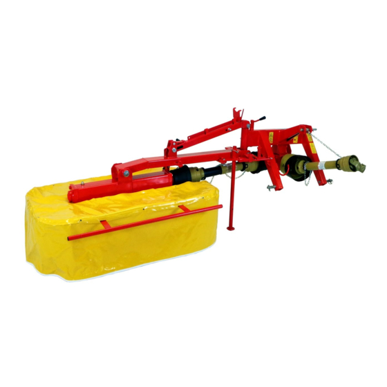
IBEX TS51C Assembly Manual
Drum mower
Hide thumbs
Also See for TS51C:
- Assembly and quick start manual (22 pages) ,
- Assembly manual (22 pages) ,
- Assembly manual (20 pages)
Table of Contents
Advertisement
Quick Links
Advertisement
Table of Contents

Related Manuals for IBEX TS51C


Summary of Contents for IBEX TS51C
- Page 1 ASSEMBLY GUIDE TS51C Drum Mower...
-
Page 2: Table Of Contents
ASSEMBLY GUIDE TS51C Drum Mower CONTENTS Scope and Purpose ......................... 3 Uncrating ..........................3 Guard Installation ........................5 Three Point Hitch ........................6 Blade Installation ........................8 Attaching the Drum Unit to the 3 Point Hitch ................. 9 Attaching the Drum Unit ...................... 14 Transport Lock ........................ - Page 3 Figure 34 curtain installed with 2 holes for toe guard facing forward ........20 Figure 35 curtain straps secure to the guard frame ..............21 Figure 36 safety release bar ..................... 21 Figure 37 correct oil level in drum gearbox ................22 2022-1.0 IBEX EQUIPMENT CO.
-
Page 4: Scope And Purpose
ASSEMBLY GUIDE SCOPE AND PURPOSE This guide is limited to Ibex TS51C drum mowers (also labeled with the original manufacturer model name, Galfre FR/G 130). The guide covers models manufactured in 2020 and forward. This manual is a guide to aid in the assembly only. Consult the Quick Start Guide and User Manual for instructions on usage and safety. - Page 5 Grease the PTO drivelines before assembly. Also grease the plastic fittings on the free rotating plastic guards. It’s much easier to do before assembly. Consult the driveline manuals that are attached to the PTO drivelines for instructions on lubrication. Keep the driveline manuals for future reference. 2022-1.0 IBEX EQUIPMENT CO.
-
Page 6: Guard Installation
This cutout provides space to allow the PTO shaft to pivot to 90 degrees when the mower is switched to transport mode. This guard may already be installed. Figure 5 the smaller guard with the cut-out facing the rear (cutout may look different on your machine) 2022-1.0 IBEX EQUIPMENT CO. -
Page 7: Three Point Hitch
Position the 3 point hitch so the two arms face up. Oil the holes in the pins and in the hitch, and then oil the roll pin. Secure the roll pin with locking pliers and drive it through the holes with a hammer. 2022-1.0 IBEX EQUIPMENT CO. - Page 8 Lift the 3 point hitch unit up and install the top link pin. Adjust the length of the top link to make the 3 point hitch close to straight up and down, perpendicular to the ground. Figure 9 level the 3 point hitch unit with the top link 2022-1.0 IBEX EQUIPMENT CO.
-
Page 9: Blade Installation
Once installed, be sure the blade is on the pin and swings freely. For safety purposes, never place your hand or fingers inside the opened space between the discs. 2022-1.0 IBEX EQUIPMENT CO. -
Page 10: Attaching The Drum Unit To The 3 Point Hitch
Figure 12 move the drum unit over to the three point hitch assembly like this You will use the swivel tee subassembly shown below to connect two lift arms to the 3 point hitch assembly. Figure 13 swivel tee assembly 2022-1.0 IBEX EQUIPMENT CO. - Page 11 Don’t tighten any more all the way as the bolt will need to come back out to mount the top arm later. The nut requires a 30mm wrench. Figure 15 swivel tee in place for next step 2022-1.0 IBEX EQUIPMENT CO.
- Page 12 (we used a chair). Take note of the orientation of features so that it is installed right-side up. Figure 17 align holes in arm to swivel tee Adjust the centers of the holes to be concentric and well-aligned before attempting to push the pin through. 2022-1.0 IBEX EQUIPMENT CO.
- Page 13 2x4 or a floor jack. Doing this will prevent the pivot pin from falling out of the sleeve when the cap removed. Attach the top spring arm around the cap as shown in Figure 20 and secure the nut and bolt. Again, do not over-tighten as it needs to be able to pivot. 2022-1.0 IBEX EQUIPMENT CO.
- Page 14 Connect the lower arm to the top arm as shown in Figure 22. Be sure the bolt goes through the loop on the spring inside the top arm. The lower arm will need to be raised up at an angle to line everything up. Figure 22 top spring arm attachment to lower arm 2022-1.0 IBEX EQUIPMENT CO.
-
Page 15: Attaching The Drum Unit
Install the washer and nut on the pivot pin. The nut is a nylon locking nut and should not be over-tightened. Insert a screwdriver in the hole in the pin if necessary to prevent it from turning while securing the nut. 2022-1.0 IBEX EQUIPMENT CO. -
Page 16: Transport Lock
PTO SHAFTS Your mower comes with two different PTO shafts, one with a slip clutch and one with a one- way clutch. It’s important to install them in the correct location, and in the correct direction. 2022-1.0 IBEX EQUIPMENT CO. - Page 17 The PTO shaft with the slip clutch is attached between the 90 degree gearbox and the tractor, as shown in Figure 27. The slip clutch (the wider end with the springs) attaches to the mower, while the other end attaches to the tractor. Figure 27 shaft with slip clutch end 2022-1.0 IBEX EQUIPMENT CO.
- Page 18 As with any new implement, the shaft that attaches to the tractor may need to be cut to length. Consult the included Ibex Equipment PTO Shaft Cutting Guide. The PTO shaft with the one-way clutch installed between the 90 degree gearbox and the mower’s drum unit, as oriented in Figure 28.
-
Page 19: Pto Shaft Safety
Gather the parts shown in Figure 30. Install the mounting bolt with its head facing out, as shown, as the clearance with the handle is tight. 2022-1.0 IBEX EQUIPMENT CO. -
Page 20: Guard Installation
Figure 31 pivot restrictor plate and handle shown installed from side GUARD INSTALLATION The front guard frame has 6 holes and a pin that slides into the tubing of the rear frame as shown. 2022-1.0 IBEX EQUIPMENT CO. - Page 21 Slots must be cut out of the curtain to accommodate the two mounting bars as shown in Figure 34. Figure 34 curtain installed with 2 holes for toe guard facing forward 2022-1.0 IBEX EQUIPMENT CO.
-
Page 22: Safety Release ("Breakaway Bar")
Figure 36 when the mower is in mowing position. Figure 36 safety release bar The safety release is removed and reinstalled in a different position for transport mode. See the owner’s manual for more information regarding switching to transport mode. 2022-1.0 IBEX EQUIPMENT CO. -
Page 23: Lubrication
Verify that there is oil in the 2 gearboxes and lubricate all grease points. Some of the grease points will take more grease than usual the first time they are lubricated due to filling up the air space between the bushings. Figure 37 correct oil level in drum gearbox 2022-1.0 IBEX EQUIPMENT CO.