Sungrow SC50HV Quick Installation Manual
Hide thumbs
Also See for SC50HV:
- User manual (79 pages) ,
- User manual (84 pages) ,
- Quick installation manual (12 pages)
Advertisement
Quick Links
SC50/60/75HV
Guide
This guide provides a general instruction of the installation procedures of
SC50/60/75HV.
In no case shall this guide substitute for the user manual or related notes on
the device.
Make sure to read over, fully understand and strictly follow the detailed
instructions of the user manual and other related regulations before installing
the equipment. The user manual can be downloaded by visiting the website
at http://support.sungrowpower.com/; or it can be obtained by scanning the
QR code on the side of the equipment or the back cover of the Quick
Guidance.
Any violation could result in personal death or injury or device damage.
1 Unpacking and Inspection
Remove the backplate and fasteners from the packaging.
Step 1
Inspect the converter for visible damages and check the
Step 2
completeness of the delivery contents according to the inner
packing list.
Contact your supplier if any of the contents is missing. The converter
is unavailable if any damage is detected.
Quick
Installation
1
Advertisement

Subscribe to Our Youtube Channel
Related Manuals for Sungrow SC50HV


Summary of Contents for Sungrow SC50HV
- Page 1 SC50/60/75HV Quick Installation Guide This guide provides a general instruction of the installation procedures of SC50/60/75HV. In no case shall this guide substitute for the user manual or related notes on the device. Make sure to read over, fully understand and strictly follow the detailed instructions of the user manual and other related regulations before installing the equipment.
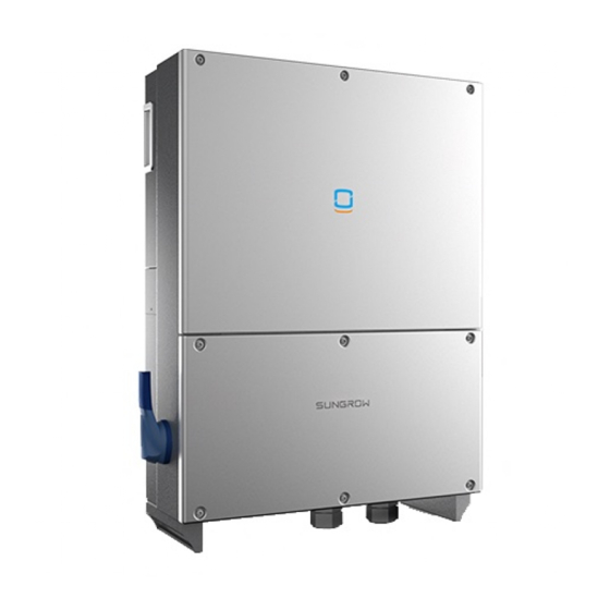
- Page 2 Fig. 1-1 Scope of delivery *Images shown here is for reference only! Actual product you receive may differ. Item Name Description PCS unit Backplate It is used for mounting PCS onto the wall. Documents include quality certificate, packing list, Documents product test report, and quick user manual.
- Page 3 2 Mounting Converter onto the metal frame 2-1 Installation Site Selection Requirement for wall materials Requirement for installation height Flammable wall Flammable material or Ground material gas near the installation Requirement for installation angle Requirement for installation space (The fans are maintained on the left side of the converter, and a larger clearance is required.)
- Page 4 Cool air Hot air ≥600mm/23.6in ≥800mm/31.5in ≥450mm/17.7in Ground 2-2 Install the converter Select the installation location and regulate the clearances of multiple converters, referring to the user manual. Move the converter to the installation site with the help of another person or the lifting device by means of the handles.
- Page 5 Install backplate Name Description Hexagon nut Spring washer Flat washer Screw bolt M10*45 Metal frame Backplate Lift the converter above the backplate and then slide down to make sure Step 1 they match perfectly. After putting the converter on the backplate, secure the converter to the Step 2 backplate with two M4×16 screws (fix screw hole has its own nut).
-
Page 6: Electrical Connection
3 Electrical Connection Death hazards due to high voltage existing inside the converter! Make sure that all the DC and AC cables to the converter are not live before you start the electrical work. Do not turn on the AC side or DC side circuit breaker until all converter electrical connections have completed. - Page 7 Name Description Configuration circuit Communication cable connection board configuration Battery crimping terminal Battery input cable access AC crimping terminal AC output cable access PE terminals PE cable access Protective components to safely disconnect AC switch from AC side. Communication cable For Communication cable connection glands Knockout diameter for COM cable is 28.5mm...
- Page 8 10 Ohm. In European and Asia-Pacific regions, this secondary protective grounding connection cannot replace the connection of the terminals in the AC wiring. Both shall be reliably grounded. Otherwise, Sungrow will not take any responsibility for the possible consequences.
- Page 9 6~7N.m In other regions (such as North America), the secondary protective grounding can be implemented in accordance with the relevant standards of the country/region. 3-5 AC Connection Install an AC circuit breaker (recommended specification 125A/690V) between the PCS and the AC side. Disconnect AC circuit breaker to prevent it from inadvertently Step 1 reconnecting.
- Page 10 described in the figure below. B=E+(2~3)mm Fig. 3-1 Crimping the lugs Crimp the cord end terminals. Step 5 Loosen the swivel nut of the gland terminal (Marked as “AC Output”) and Step 6 select an appropriate seal according to cable outer diameter. Lead the cable through the swivel nut and seal successively.
- Page 11 Screw cap-nut tightly onto the cable. Step 8 Seal the gaps between the AC cable and the gland inside the lower part Step 9 of the cabinet with duct seal. 3-6 Internal PE Cable Connection Prepare the cable and crimp cord end terminal. Step 1 L = E + (2~3)mm 1: Heat shrink tubing...
- Page 12 3-7 Battery Connection Rotate the BAT switch to the “OFF” Step 1 position. Strip the insulation layer of the DC cable to Step 2 proper length according to the DC cable specification. Insert the end of the DC cable to the cable socket that matches with the Step 3 M10 bolt and tighten it with the proper tool.
- Page 13 Once positive and negative inputs are short-circuited, it can cause unrecoverable damage to the PCS. Sungrow shall hold no liability for any possible consequences caused by ignorance of this warning. Pull the cable gently to make sure it is secured.
- Page 14 Seal the gap between the cable and the gland with duct seal or other suitable materials to prevent the entry of foreign bodies or moisture and ensure long-term and normal operation of the PCS. Connect the communication devices. Refer to other manuals and Step 6 documents if there are other devices.
- Page 15 4 Commissioning Before starting the PCS, make sure all installation and connections are completed and verified. If all of the items mentioned above meet the requirements, proceed as follows to start up the PCS for the first time. Make sure all the above-mentioned items meet the requirements. Step 1 Close the external AC circuit breaker.
Need help?
Do you have a question about the SC50HV and is the answer not in the manual?
Questions and answers