Table of Contents
Advertisement
Quick Links
Advertisement
Table of Contents

Subscribe to Our Youtube Channel
Related Manuals for RADWAG MW-01-A


Summary of Contents for RADWAG MW-01-A
- Page 2 JANUARY 2022...
- Page 3 PRECAUTIONS Prior to installation, operation or maintenance activities, carefully read this user manual. Follow the instructions strictly. Prior to the first use, carefully read this user manual. Use the device only as intended. Protect the device against considerable temperature variation, solar and UV radiation, substances causing chemical reactions.
-
Page 4: Table Of Contents
CONTENTS 1. INTENDED USE ..............................5 2. WARRANTY CONDITIONS ..........................5 3. MAINTENANCE ..............................5 4. SERVICE AND REPAIR ............................. 6 5. RECYCLING ............................... 6 6. MECHANICAL DESIGN ............................. 6 6.1. General View ..............................7 6.2. Dimensions ..............................7 6.3. Connectors ..............................7 6.4. -
Page 5: Intended Use
1. INTENDED USE The MW-01-A mass converter is designed to be a component of an industrial load cell scale. Depending on the needs, communication with the mass converter can be carried out via the following communication interfaces: RS232, RS485, Ethernet, Profibus, Profinet, Ethernet IP. The MW-01-A mass converter is compatible with indicators and PC. -
Page 6: Service And Repair
5. RECYCLING The MW-01-A mass converters must be recycled, they are not to be treated as a regular household waste. Devices to be decommissioned must be decommissioned in accordance with valid legal regulations. -
Page 7: General View
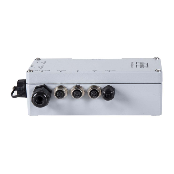
6.1. General View Figure 1. MW-01-A mass converter, general view 6.2. Dimensions Figure 2. MW-01-A mass converter, dimensions 6.3. Connectors Figure 3. Arrangement of connectors... -
Page 8: Rs232 Connector
Pin6 – 5VDC Pin7 – NC Pin8 – NC 6.5. Inputs/Outputs Standard MW-01-A mass converter is equipped with 3 optoisolated inputs and 3 semiconductor outputs (semiconductor relays). The signals are fed through M12 8P connectors. Pin1 – IN1 Pin2 – IN2 Pin3 –... -
Page 9: Technical Specifications
6.5.1. Technical Specifications Output parameters Output quantity Output type Solid-state relay Maximum output current 0.5 A DC Maximum output voltage 30 VDC, AC Input parameters Input quantity Input type Optoisolated Input voltage range 5 - 24 VDC 6.6. Main Board Sockets Figure 4. -
Page 10: Technical Specifications
6.7. Technical Specifications Housing Metal Ingress protection IP66 12 ÷ 24 VDC Power supply -10 °C ÷ +40 °C Operating temperature OIML class III or IIII n≤10 000 Verification units Maximum input signal gain 19.5 mV 1.95 µV Maximum voltage per verification unit 0.5 µV Minimum voltage per verification unit 50 Ω... -
Page 11: Models
'MwManager' software is to be found in the software user manual. 8. INSTALLER INSTRUCTION The MW-01-A mass converter can be a base component of a load cell scale. 8.1. 6-Wire Load Cell Connection Connect 6-wire load cell to the main board following the diagram below:... -
Page 12: 4-Wire Load Cell Connection
Figure 5. Connecting 6-wire load cell Socket Load cell signal REMARKS SHIELD Refer to section 8.3 REF+ SENSE + JP2 not to be soldered REF- SENSE - JP4 not to be soldered OUTPUT+ OUTPUT- +EXC INPUT+ -EXC INPUT- 8.2. 4-Wire Load Cell Connection Connect 4-wire load cell to the main board following the diagram below:... -
Page 13: Connecting Load Cell's Cable Shield
Figure 6. Connecting 4-wire load cell Socket Load cell signal REMARKS SHIELD Refer to section 8.3 REF+ JP2 soldered REF- JP4 soldered OUTPUT+ OUTPUT- +EXC INPUT+ -EXC INPUT- 8.3. Connecting Load Cell’s Cable Shield Scale with a mass converter in Scale compact mechanical... -
Page 14: Factory Parameters
9. FACTORY PARAMETERS In order to be able to edit and save factory parameters to the MW-01-A mass converter's memory, it is necessary to put a jumper allowing access to the factory parameters. 9.1. Factory Parameter Access Plug the power supply of the MW-01-A mass converter to the mains. -
Page 15: Factory Parameters
Figure 8. Factory parameters window 9.2. Factory Parameters NAME DEFAULT VALUES REMARKS Adjustment Range 3.009 Maximum range + 9e overload. Switching point of range II. For single Range 2 threshold range balances set 0. Switching point of range III. For I-range Range 3 threshold or II-range scales set 0 value. -
Page 16: Parameter Value Modification
Start mass determination (refer Determine start mass section 9.4.1). Determine adjustment Adjustment factor determination (read factor section 9.4.2). Restoring default adjustment parameter Set defaults settings. Section linearity correction (refer to Linearity section 9.5). Weighing 0.1 ÷ 5 Autozero range 0.25 Autozero range (in divisions). -
Page 17: Factory Adjustment
9.4. Factory Adjustment 9.4.1. Start Mass Determination Unload the weighing pan. Go to <Adjustment> tab, press <Determine start mass> button, message <Unload the pan> is displayed. Press <OK> button to confirm, start mass adjustment begins. Upon completion, message: <Start mass determination completed successfully>... -
Page 18: Linearity Correction
9.5. Linearity Correction „Linearity” tab enables access to thresholds and linearity deviations. Figure 9. Linearity correction window Where: Press to zero all threshold values. To zero the deviations and the thresholds, select <Zero thresholds while zeroing linearity> option. Press to zero a value of a particular threshold/deviation. Press to determine deviation of a particular threshold. -
Page 19: Gcor
(longitudinal change), the value of <g-cor.> parameter must be corrected. 10. OPTIONAL EXTENSION MODULES The MW-01-A mass converter can be equipped with additional optional interface modules: ETHERNET, RS485, PROFIBUS, PROFINET, ETHERNET IP and analog outputs (4-20 mA or 0-10 V). The modules are installed inside the device. -
Page 20: Rs485 Module
The 309R module, expanding the functionality of the MW-01-A converter by RS485 interface, is installed on an intermediate board, 385R ver. B. The module is intended to be mounted inside the MW-01-A. For the 309R module, an extra M12 8P connector is installed on the housing. -
Page 21: Ethernet Ip Module
10.4. ETHERNET IP Module The 494R module, combined with AB6003 module, expands the functionality of the MW-01-A converter by Ethernet IP interface. The module is intended to be mounted inside the indicator. For the 494R module, a hermetic RJ45 connector is installed on the housing. -
Page 22: Analog Output Module
10.5. Analog Output Module The 495 R module expands the functionality of the MW-01-A converter by an analog output, 4-20 mA, and a voltage output, 0-10 V. The module is intended to be mounted inside the MW-01-A. The 495R module is a passive module. -
Page 23: Wiring Diagrams Of The Current Loop Module
10.5.1. Wiring Diagrams of the Current Loop Module Voltage output wiring diagram WIRE COLOURS Colour Signal pink grey yellow +24V DC green Current output wiring diagram WIRE COLOURS Colour Signal white grey yellow +24V DC green 10.5.2. Technical Specifications Output resolution 16bit Linearity error +/- 0.01 %... -
Page 24: Profibus Module
The AB6000 module, expanding the functionality of the MW-01-A converter by PROFIBUS interface, is installed on an intermediate board, 385R ver. A. The module is intended to be mounted inside the MW-01-A. For the AB6000 module, an extra M12 5P connector is installed on the housing (with coding respective for the PROFIBUS standard). -
Page 25: Accessories
Figure 15. Profinet Module 11. ACCESSORIES MW-01-A – computer cable PT0020 MW-01-A – Ethernet cable PT0212 MW-01-A – 3IN cable PT0256 MW-01-A – 3OUT cable PT0256 MW-01-A – RS485 cable PT0383...
Need help?
Do you have a question about the MW-01-A and is the answer not in the manual?
Questions and answers