Table of Contents
Advertisement
Quick Links
Features
With "sandwich" structure, it is easy to be installed
between DB-01 base and a detector.
Three working modes settable (Mode I, II, III, and
the latter two available with pre-alarm state).
16 tones of sound and bright flashing light.
Electronically addressed. The address and tones
can be modified in field.
Tone 14 and 16 are certified by EN54-3.
Description
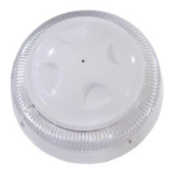
DI-9406 Addressable Flashing Beacon Base is
installed in field to warn people for evacuation with
audible and visual alarm in case of a confirmed fire.
The flashing beacon base can communicate with fire
alarm control panel (FACP) through a built-in
microprocessor. On receiving a start command from
the FACP, the microprocessor will control the buzzer to
generate the pre-set fire alarm sound and light the
bright LED.
Wiring and Connection
Terminals of the flashing beacon base are shown in
Fig. 1.
Fig. 1
Z1(1), Z2(3): Signal loop of FACP, polarity-insensitive.
Recommended Wiring
2
1.0mm
or above fire cable, subject to local codes.
Installation
Warning: Before installing the flashing beacon
base, disconnect power from the loop and verify
that all the bases are securely fixed and that the
wiring is correct on each base.
1
Before installation, make sure the enclosure is
free from scratch or distortion, and labels are
complete.
2
Installation schematic of the flashing beacon base
is shown in Fig. 2.
3
Secure the detector base (Fig. 4) with 2 tapping
screws, and wire them properly. Align the
orientation mark B on the flashing beacon base to
mark C of detector base, and rotate the flashing
beacon base clockwise to D. Refer to Fig. 3 and 4.
4
If the flashing beacon base comes with a cover,
align the orientation mark on the cover to mark A
of the flashing beacon base (Fig.1), and rotate the
cover clockwise to B. If it's used as detector base,
remove the cover and install the detector on it with
the same method.
Fig. 2
30308005
Addressable Flashing Beacon Base
Application
The flashing beacon base can be used as the base of
intelligent heat and smoke detectors to combine
detection and alarm in a single device. It can be
connected to the loop of FACP without additional
power supply.
Working Mode Setup and Tone Selection
The flashing beacon base has three working modes.
The factory default is tone 14, mode I.
The flashing beacon base has 16 tones, the setup of
which also decides the setup of working modes.
If the flashing beacon base is set with one of the
If it is set with one of the tones from No. 17 to 32, it
If it is set with one of the tones from No. 33 to 48, it
Tone 1~16, 17~32 and tone 33~48 are completely
Working Modes:
Electric Box
Base
Flashing Beacon Base
Cover or Detector
DI-9406
B
Fig. 3
tones from No. 1 to 16, it works in Mode I.
works in Mode II.
works in Mode III.
the same by one-to-one correspondence, with the
only difference that they work in different modes.
Please refer to the table of tones.
Mode
Address
Single address,
occupying one
loop point
Standalone. The beacon
Note: Detector
I
base gives alarm signal
& beacon base
when started.
must have
different
addresses.
The beacon base gives
Dual addresses,
pre-alarm signal when
sharing high
II
starting the higher address
address with
and alarm signal when
detector
starting the lower address.
The beacon base gives
Occupying dual
pre-alarm signal when
III
addresses
starting the lower address
individually
and alarm signal when
starting the higer address.
2831-CPR-F0036
GST-0003-01
13
548e/07
C
D
Fig. 4
Type of fire alarm
Issue 1.07
Advertisement
Table of Contents

Subscribe to Our Youtube Channel
Related Manuals for GST DI-9406


Summary of Contents for GST DI-9406
- Page 1 Tone 14 and 16 are certified by EN54-3. Description DI-9406 Addressable Flashing Beacon Base is 548e/07 installed in field to warn people for evacuation with audible and visual alarm in case of a confirmed fire.
- Page 2 Limited Warranty Mode I; if the number falls into the range of 17 to 32, it GST warrants that the product will be free from defects works in Mode II; if the number falls into the range of in design, materials and workmanship during the 33-48, it works in Mode III.
- Page 3 Appendix Operation Performance Data for LPCB Approved Tones Operational performance Tone 14 Operational performance Maximum Volume dB(A) Horizontal Plane Vertical Plane Angle Max 28 V Min 20V Max 28V Min 20V 15° 82.6 dB(A) 83.7 dB(A) 79.2 dB(A) 79.3 dB(A) 45°...
- Page 4 This Data Sheet is subject to change without notice. Please contact GST for more information or questions. Gulf Security Technology Co., Ltd. No. 80, Changjiang East Road, QETDZ, Qinhuangdao, Hebei, P. R. China 066004 Tel: +86 (0) 335 8502434 Fax: +86 (0) 335 8502532 service.gst@fs.utc.com www.gst.com.cn...
Need help?
Do you have a question about the DI-9406 and is the answer not in the manual?
Questions and answers