Table of Contents
Advertisement
Quick Links
Advertisement
Table of Contents

Related Manuals for Anywave PA-U1D-C-FA


Summary of Contents for Anywave PA-U1D-C-FA
- Page 1 ANYWAVE PA-U1D-C-FA User Manual Version 2.2 – September 25, 2019...
- Page 2 This equipment complies with relevant portions of Parts 2, 73, & 74 of the FCC rules governing LPTV operation. Disclaimer Information provided by Anywave Communication Technologies is believed to be accurate and complete; however, no liability can be assumed for its use. The manufacturer makes no representations or warranties, either expressed or implied, by or with respect to anything in this manual, and shall not be liable for any implied warranties of fitness for a particular purpose or for any indirect, special, or consequential damages.
- Page 3 Returns and Exchanges Written approval and a Return Authorization Number (RAN) are required from Anywave for all equipment returns. Please direct all return inquiries to the Anywave Service Department at support_us@anywavecom.com, providing the Sales Order number and Serial Number(s) of the equipment.
- Page 4 The installation, operation, maintenance and service of this equipment involves risks both to personnel and equipment and must ONLY be performed by qualified personnel exercising due care. Anywave Communication Technologies, Inc. shall not be responsible for injury or damage resulting from improper handling or from the use of improperly trained or inexperienced personnel performing such tasks.
-
Page 5: Table Of Contents
PA-U1D-C-FA User Manual Contents 1 Product Appearance ..................6 1.1 Front Panel ............................ 6 1.2 Back Panel ............................ 7 2 Specifications ....................8 3 Control Interface ....................9 3.1 Web Interface ..........................9 3.2 Local (Touch Screen) User Interface ..................14 3.2.1. -
Page 6: Product Appearance
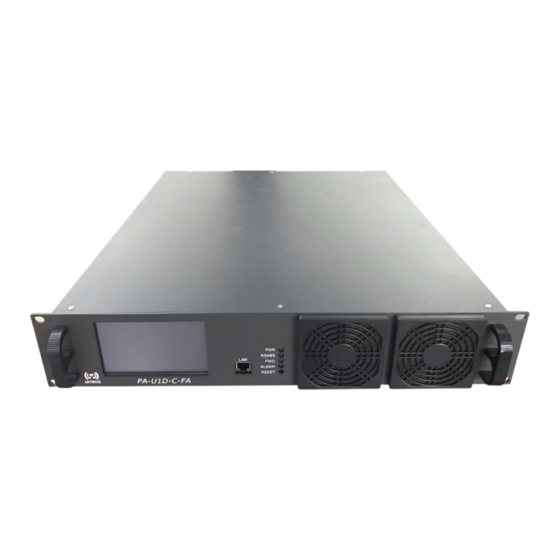
PA-U1D-C-FA User Manual 1 Product Appearance 1.1 Front Panel LED_PWR The green light will be on when the DC voltage of the internal power supply is within the normal range (48 VDC ~ 52 VDC). The green light will flash when the DC voltage of the internal power supply is out of the normal range (48 VDC ~ 52 VDC). -
Page 7: Back Panel
PA-U1D-C-FA User Manual 1.2 Back Panel RF IN-A/RF IN-B Connector: 50 Ω Impedance: Note: If input power from RF_IN is lower than the rated input value, the output power will be lower than the rated output power accordingly. This is because the PA has a fixed gain. If the input level from RF_IN is higher than the rated value, it will result in RF output distortion and performance deterioration. -
Page 8: Specifications
PA-U1D-C-FA User Manual 2 Specifications Environment Operation Temperature: C ~ +60 C (+14 F ~ +140 Operation Humidity: 20 % ~ 90 % (non-condensing) Atmospheric Pressure: 86 kPa ~ 106 kPa Power Supply Voltage: 90 ~ 264 VAC ... -
Page 9: Control Interface
PA-U1D-C-FA User Manual 3 Control Interface 3.1 Web Interface Enter the IP address of the PA (the default value is 192.168.1.210) in a web browser's address bar to cause a login window to pop up. The “admin” tier provides full status and control of the PA and is accessed with a username and password of "anywavecom"... - Page 10 6) FREQ is the current channel frequency read from the exciter. If the internal communication between the exciter and the PA is lost (via RS485), or the PA is not connected with an Anywave exciter, then this parameter may not reflect the actual channel information.
- Page 11 PA-U1D-C-FA User Manual Note: 1) FWD-ADJ/REF-ADJ/REJT-ADJ: These are used to calibrate the forward power, reflected power and rejected power meters. Calibration values may vary by channels. Every amplifier is calibrated at the channel specified by order in the factory before shipment. If you would like to run the amplifier at a different channel (within the allowed range of the amplifier) or to calibrate the readings again for any reason, please contact the manufacturer for technical support.
- Page 12 PA-U1D-C-FA User Manual Once alarms are cleared, you can slowly increase the exciter’s drive or lower the ATT value to bring the amplifier back to the original level. 4) RF-SWITCH: It is to turn the TX of the amplifier ON or OFF.
- Page 13 PA-U1D-C-FA User Manual Note: 1) This section is to set the network configuration of the amplifiers. It allows users to set the IP, mask, and gateway of the amplifier. 2) If a user cannot recall the IP and therefore cannot log in remotely after making a change, he can either reset the IP back to default (192.168.1.210) from its front panel RESET button by pressing...
-
Page 14: Local (Touch Screen) User Interface
PA-U1D-C-FA User Manual 3.2 Local (Touch Screen) User Interface 3.2.1. Home Screen Turn on the power supply and the PA enters the initialization process, and after 5 seconds, the PA enters the Home screen (as shown below). The home screen is divided into 4 parts: Title Bar (left column), Power Metering (upper right), Block Diagram (middle right) and Status Bar (lower right), as shown below. -
Page 15: A/B Exciter Icon Screen
PA-U1D-C-FA User Manual indicates the TX is ON. When it is RED, it indicates the TX is OFF. FWD: the Forward Power Meter. Touching the white display box of FWD will toggle its display units between “dBm” and “W”. - Page 16 PA-U1D-C-FA User Manual automatically switch back to the original Exciter in the event of a problem with the on-air (standby) exciter. So the PA will continue to automatically switch to the standby exciter in the event of a problem with the on-air exciter.
-
Page 17: Config Screen
PA-U1D-C-FA User Manual Please note that the Exciter(s) communicates via an RS-485 bus to the PA. In a single drive TX, the Exciter will be configured with an RS-485 address ID of 80H (as found under the Exciter CONFIG submenu) corresponding with Exciter A. - Page 18 PA-U1D-C-FA User Manual including IP, Mask, and Gateway. The AGC screen is used to turn the PA AGC On/Off and to change the target AGC output power level. Network Screen: The User can check and set all the Controller network information in this screen.
- Page 19 PA-U1D-C-FA User Manual mistake, press Cancel to exit the setting mode. Don’t press Ok without entering a valid number, otherwise, the system will fill it with all zeros instead. AGC Screen: This screen is used to set the AGC Reference output power of the PA and to turn the PA AGC ON/OFF.
-
Page 20: Status Screen
PA-U1D-C-FA User Manual 3.2.4. Status Screen Status Screens: As mentioned above, pressing the “Amplifier” icon on the Home page, will navigate to the Amplifier Status Screens. Temp: Temperature of the amplifier V50: Reading of 50 V power supply of the amplifier ... - Page 21 PA-U1D-C-FA User Manual ACT-PA-U1D-USR-DOC-V2.2, 09/25/2019 Page 21 of 22...
- Page 22 PA-U1D-C-FA User Manual Anywave Communication Technologies Inc. 300 Knightsbridge Parkway, Suite 150, Lincolnshire, IL 60069 Tel: (847) 415-2258 Fax: (847) 415-2112 Email: sales_us@anywavecom.com http://www.anywavecom.net/ ACT-PA-U1D-USR-DOC-V2.2, 09/25/2019 Page 22 of 22...
Need help?
Do you have a question about the PA-U1D-C-FA and is the answer not in the manual?
Questions and answers