Table of Contents
Advertisement
HARBOR BREEZE and logo design are trademarks or
registered trademarks of LF, LLC. All rights reserved.
ATTACH YOUR RECEIPT HERE
Purchase Date _________________________
Questions, problems, missing parts? Before returning to your retailer, call our customer
service department at 1-888-251-1003, 8 a.m. - 8 p.m., EST, Monday - Sunday. You could also
contact us at partsplus@lowes.com or visit www.lowespartsplus.com.
JS21052
1
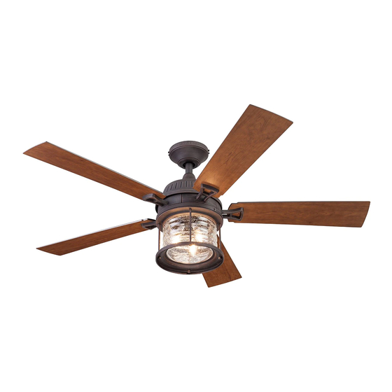
ITEM #0803776
STONECROFT
CEILING FAN
MODEL #41946
Español p. 20
RATED FOR
DAMP LOCATIONS
Advertisement
Table of Contents

Subscribe to Our Youtube Channel
Related Manuals for Harbor Breeze STONECROFT 41946


Summary of Contents for Harbor Breeze STONECROFT 41946
- Page 1 ITEM #0803776 STONECROFT CEILING FAN MODEL #41946 HARBOR BREEZE and logo design are trademarks or registered trademarks of LF, LLC. All rights reserved. Español p. 20 RATED FOR ATTACH YOUR RECEIPT HERE DAMP LOCATIONS Purchase Date _________________________ Questions, problems, missing parts? Before returning to your retailer, call our customer service department at 1-888-251-1003, 8 a.m.
-
Page 2: Table Of Contents
TABLE OF CONTENTS Package Contents..............3 Hardware Contents. -
Page 3: Package Contents
PACKAGE CONTENTS PART DESCRIPTION QUANTITY Downrod Downrod Pin (preassembled to Downrod [A]) Downrod Clip (preassembled to Downrod [A]) Mounting Bracket Canopy (preassembled to Mounting Bracket [D]) Canopy Cover (preassembled to Canopy [E]) Motor Assembly Light Pan Light Pan Screw (preassembled to Light Pan [H]) Light Cage Screw (preassembled to Light Cage [Q]) Set Screw (preassembled to Motor Assembly [G]) Yoke Cover... -
Page 4: Hardware Contents
HARDWARE CONTENTS (shown actual size) Wire Connector Blade Screw Blade Washer Motor Screw Qty. 6 Qty. 15 Qty. 15 10 + 1 extra + 1 extra + 1 extra + 1 extra... -
Page 5: Safety Information
SAFETY INFORMATION Please read and understand this entire manual before attempting to assemble, operate or install the product. • Before you begin installing the fan, disconnect the power by removing fuses or turning off the circuit breakers. • Make sure all electrical connections comply with local codes, ordinances, the National Electrical Code and ANSI/NFPA 70-199. -
Page 6: Preparation
SAFETY INFORMATION CAUTION: Read all instructions and safety information before installing your new fan. Review the accompanying assembly diagrams. CAUTION: Be sure the outlet box is properly grounded or that a ground (green or bare) wire is present. CAUTION: Carefully check all screws, bolts and nuts on the fan motor assembly to ensure they are secured. -
Page 7: Initial Installation
INITIAL INSTALLATION 1. Turn off the circuit breakers and the wall switch to the fan supply line leads. DANGER: Failure to disconnect the power supply prior to installation may result in serious injury or death. 2. Determine the mounting method to use. Standard Mounting is best suited for ceilings 8 ft. - Page 8 INITIAL INSTALLATION 4. Loosen all four mounting bracket screws (U) on mounting bracket (D), then completely remove the two mounting bracket screws (U) from the round holes of canopy (E). Set aside for later use. Detach mounting bracket (D) from canopy (E). 5.
-
Page 9: Standard Or Angle Mounting Instructions
STANDARD OR ANGLE MOUNTING INSTRUCTIONS 7. Insert the downrod (A) through the canopy (E) and yoke cover (L). Feed the wires from the motor assembly (G) through the downrod (A). 8. Slide the downrod (A) into the yoke of the motor assembly (G), align the holes, then re-install the downrod clip (C) and downrod pin (B). - Page 10 STANDARD OR ANGLE MOUNTING INSTRUCTIONS 10. If you decided to cut back the lead wire in Step 9, strip 1/2 in. of insulation from the end of the wires. Twist the stripped ends of each strand of wire within the insulation with pliers (not included).
-
Page 11: Wiring
WIRING WARNING: To reduce the risk of fire, electrical shock or personal injury, wire connectors provided with this fan are designed to accept only one 12-gauge house wire and two lead wires from the fan. If your house wire is larger than 12-gauge and there is more than one house wire to connect to the two fan lead wires, consult an electrician for the proper size wire connectors to use. -
Page 12: Final Installation
FINAL INSTALLATION 1. Align the canopy (E) over the loose mounting bracket screws (U) preassembled on mounting bracket (D) and turn canopy (E) in a clockwise direction. Secure the canopy (E) with the mounting bracket screws (U) previously removed (Step 4, page 8). Tighten all mounting bracket screws (U) securely. - Page 13 FINAL INSTALLATION 4. Remove one of the four fitter plate screws (P) located on the underside of the motor assembly (G) and loosen the other three screws. Align the screw holes of the light pan (H) with the loosened fitter plate screws (P) and turn in a clockwise direction.
- Page 14 FINAL INSTALLATION 7. Remove the three light cage screws (J) from the top edge of the light cage (Q). Then, align the screw holes in the light cage (Q) with the screw holes in the light pan (H) and secure the light cage (Q) to the light pan (H) using the light cage screws (J).
-
Page 15: Operating Instructions
OPERATING INSTRUCTIONS 1. To operate the fan using the remote, press and release the following buttons: 000 - High fan speed 00 - Medium fan speed 0 - Low fan speed O - Turns the fan off. Remote - Press this button quickly to turn the lights on or off. -
Page 16: Care And Maintenance
CARE AND MAINTENANCE At least twice each year, tighten all screws on the fan. Clean the motor housing with only a soft brush or lint-free cloth to avoid scratching the finish. Clean the blades with a lint-free cloth. Bulb Replacement: Use 40-watt max. E12-base LED, CFL or incandescent bulbs. Halogen bulbs are not recommended for this item. - Page 17 TROUBLESHOOTING PROBLEM POSSIBLE CAUSE CORRECTIVE ACTION 1. The blades and/or blade arms 1. Check and tighten all screws that hold are loose. the fan blades to the blade arms and the blade arms to the motor. 2. The blades are unbalanced. 2.
-
Page 18: Limited Lifetime Warranty
LIMITED LIFETIME WARRANTY The manufacturer warrants this fan to be free from defects in workmanship and materials present at time of shipment from the factory for a lifetime from the date of purchase by the original purchaser. The retailer also warrants that all other fan parts, excluding any glass or plastic blades, to be free from defects in workmanship and material at the time of shipment from the factory for a period of one year after the date of purchase by the original purchaser. -
Page 19: Replacement Parts List
REPLACEMENT PARTS LIST For replacement parts, call the customer service department at 1-888-251-1003, 8 a.m. - 8 p.m., EST, Monday - Sunday. You could also contact us at partsplus@lowes.com or visit www.lowespartsplus.com. PART DESCRIPTION PART# Downrod 4L000011110 Mounting Bracket 4L000011290 Canopy 4L000014640 Canopy Cover...
Need help?
Do you have a question about the STONECROFT 41946 and is the answer not in the manual?
Questions and answers