Table of Contents
Advertisement
Harbor Breeze® is a registered trademark
of LF, LLC. All Rights Reserved.
ATTACH YOUR RECEIPT HERE
Purchase Date _________________________
Questions, problems, missing parts? Before returning to your retailer, call our customer
service department at 1-800-643-0067, 8 a.m. - 8 p.m., EST, Monday - Sunday.
AR19002
NORANDA BAY
1
ITEM #1022959, 41536791
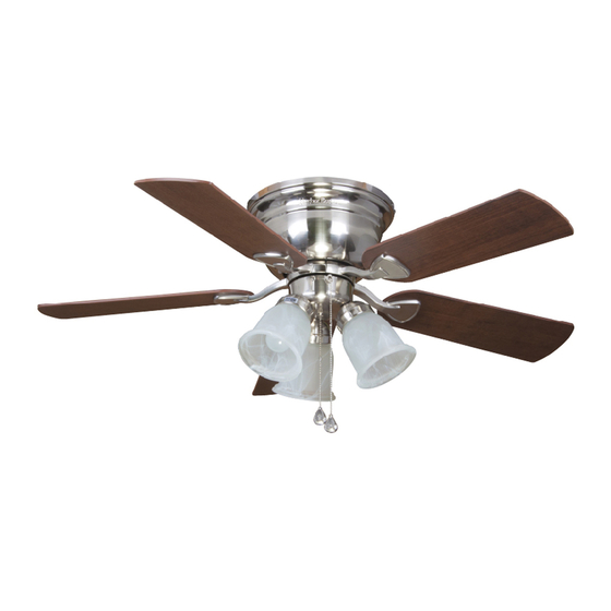
CEILING FAN
MODEL #41161
Español p. 23
Français p. 19
Advertisement
Table of Contents

Related Manuals for Harbor Breeze 41161


Summary of Contents for Harbor Breeze 41161
- Page 1 CEILING FAN MODEL #41161 Español p. 23 Français p. 19 Harbor Breeze® is a registered trademark of LF, LLC. All Rights Reserved. ATTACH YOUR RECEIPT HERE Purchase Date _________________________ Questions, problems, missing parts? Before returning to your retailer, call our customer service department at 1-800-643-0067, 8 a.m.
-
Page 2: Table Of Contents
TABLE OF CONTENTS Package Contents ..............3 Hardware Contents . -
Page 3: Package Contents
PACKAGE CONTENTS PART DESCRIPTION QUANTITY Motor Housing Upper Mounting Bracket Motor Lower Mounting Bracket (preassembled to Motor [C]) Light Kit Motor Housing Screw (preassembled to Upper Mounting Bracket [B]) Glass Shade Blade Arm Blade Bulb Mounting Bracket Screw (preassembled to Lower Mounting Bracket [D]) Fitter Plate Screw (preassembled to Fitter Plate [M]) Fitter Plate (preassembled to Motor [C]) Motor Screw (preassembled to Motor Assembly [C]) -
Page 4: Hardware Contents
HARDWARE CONTENTS Wire Connector Blade Screw Blade Washer Pull Chain Extension Qty. 3 Qty. 15 Qty. 15 Qty. 2 + 1 extra + 1 extra + 1 extra Secondary Spring Secondary Support Washer Motor Screw Washer Support Screw Qty. 1 1 extra Qty. -
Page 5: Safety Information
SAFETY INFORMATION Please read and understand this entire manual before attempting to assemble, operate or install the product. • Before you begin installing the fan, disconnect the power by removing fuses or turning off the circuit breakers. • Make sure all electrical connections comply with local codes, ordinances, the National Electrical Code, and ANSI/NFPA 70-199. -
Page 6: Preparation
SAFETY INFORMATION CAUTION: Read all instructions and safety information before installing your new fan. Review the accompanying assembly diagrams. CAUTION: Be sure the outlet box is properly grounded or that a ground (green or bare) wire is present. CAUTION: Carefully check all screws, bolts and nuts on the fan motor assembly to ensure they are secured. -
Page 7: Initial Installation
INITIAL INSTALLATION 1. Turn off the circuit breakers and the wall switch to the fan supply line leads. DANGER: Failure to disconnect the power supply prior to installation may result in serious injury or death. 2. Ensure the blades (I) will be at least 30 in. from any obstructions and will be at least 7 ft. - Page 8 INITIAL INSTALLATION 4. Remove the mounting bracket screws (K) from underneath the lower mounting bracket (D). Remove the motor screws (N) and set aside for later. Note: The notch in the fitter plate allows a Phillips screwdriver (not included) access to motor screws. 5.
-
Page 9: Secondary Hanging System
SECONDARY HANGING SYSTEM WARNING: Secondary support is required for this Braided Cable product. Failure to follow the steps below could result in property damage and/or person injury. Brace 1. Feed the loop of the braided cable, attached to the motor (C), up through the outlet box mounted in the ceiling. -
Page 10: Wiring
WIRING WARNING: To reduce the risk of fire, electrical shock or personal injury, wire connectors provided with this fan are designed to accept only one 12 gauge house wire and two lead wires from the fan. If your house wire is larger than 12 gauges and there is more than one house wire to connect to the two fan lead wires, consult an electrician for the proper size wire connectors to use. -
Page 11: Final Installation
FINAL INSTALLATION 4. Temporarily lift the motor housing (A) to the upper mounting bracket (B) to determine which two motor housing screws (F) in the sides of the upper mounting bracket (B) align with the slotted holes in the top edge of the motor housing (A). - Page 12 FINAL INSTALLATION 7. Install the blade arm (H) to the underside of the motor assembly (C) with motor screws (N) previously removed (Step 4, page 8). Tighten with Phillips screwdriver (not included). Repeat for each blade arm (H). Note: The notch in the fitter plate allows a Phillips Notch screwdriver (not included) access to motor screws.
- Page 13 FINAL INSTALLATION 10. Unscrew the socket ring (O) from the socket of the light kit (E). Then lift the glass shade (G) into the light cup. Secure the glass shade (G) by reinstalling the socket ring (O). 11. Install bulbs (J) into the sockets on the light kit (E). Important: Make sure you allow the bulbs (J) and light kit (E) to cool before you replace the bulbs.
-
Page 14: Operating Instructions
OPERATING INSTRUCTIONS 1. The fan pull chain has four positions to control fan speed. One pull is HIGH, two is MEDIUM, three is LOW and four turns the fan OFF. The light pull chain is used to turn the lights ON or OFF. Pull Chain Light Pull Chain... -
Page 15: Care And Maintenance
CARE AND MAINTENANCE At least twice each year, tighten all screws on the fan. Clean the motor housing with only a soft brush or lint-free cloth to avoid scratching the finish. Clean the blades with a lint-free cloth. Bulb Replacement: Use 40-watt max. E26-base LED, CFL or incandescent bulbs. Halogen bulbs are not recommended for this item. - Page 16 TROUBLESHOOTING PROBLEM POSSIBLE CAUSE CORRECTIVE ACTION 1. The bulbs are not installed 1. Re-install the bulb(s). correctly. 2. The light kit wire plugs are 2. Ensure that the male and female plugs The fan operates in the light kit fitter are connected not connected properly.
-
Page 17: Limited Lifetime Warranty
LIMITED LIFETIME WARRANTY The manufacturer warrants this fan to be free from defects in workmanship and materials present at time of shipment from the factory for a lifetime from the date of purchase by the original purchaser. The retailer also warrants that all other fan parts, excluding any glass or plexiglass blades, to be free from defects in workmanship and material at the time of shipment from the factory for a period of one year after the date of purchase by the original purchaser. -
Page 18: Replacement Parts List
REPLACEMENT PARTS LIST For replacement parts, call the customer service department at 1-800-643-0067, 8 a.m. - 8 p.m., EST, Monday - Sunday. PART DESCRIPTION PART# Motor Housing 4L000011870 Upper Mounting Bracket 4L000011880 Light Kit 4L000011890 Glass Shade 4L166530001 Blade Arm 4L072720000 Blade 4L083560000...
Need help?
Do you have a question about the 41161 and is the answer not in the manual?
Questions and answers