Table of Contents
Advertisement
Quick Links
Advertisement
Table of Contents

Related Manuals for Kränzle therm C 11/130


Summary of Contents for Kränzle therm C 11/130
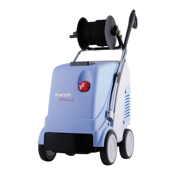
- Page 1 O p e r a t i n g m a n u a l - G B - Hot Water - High-pressure cleaners 11/130 13/180 15/150 Read and conform safety instructions before use! Keep instructions in a safe place for later use and pass them on to any future user.
-
Page 2: Dear Customer
The machine is a professional cleaning aid in all cleaning tasks, e.g.: - facades - vehicles of all types - containers - sheds - machines industry therm C 11/130 Technical data therm C 13/180 therm C 15/150 Operating pressure 30 - 130 bar 30 - 180 bar... - Page 3 Description Connections and functional parts Storage bin for spray gun and pipe Power cable Brake Winder for cable 10 Fuel tank Suction hose for detergent 11 Filler aperture for fuel High pressure hose 12 High pressure outlet Spray gun 13 Hose drum (special accessories) 16 (Burner ON- OFF) ignition 19 Thermostat 17 Brief operating instructions...
- Page 4 Description Water system The water is then directed to the safety spray pipe under pressure from the high pressure pump. The high pressure spray is formed through the nozzle on the spray pipe. The high pressure pump can also suck a detergent/caring agent and mix it with the high pressure jet.
- Page 5 Description The pump motor is protected from overload by a motor protecting switch. In case of an overload the motor is switched off by this motor protecting switch. For a restart the master switch has to be switched off and then on again. In case of a repeated switching off of the motor by the motor protecting switch the cause of the malfunction has to be removed.
- Page 6 Description Thermostat The thermostat with rotary control switch controls the temperature of the spray water. Use the rotary control switch to adjust the desired water temperature. Thermostat with rotary control switch The high pressure hose and spray equipment supplied with the machine are made of high quality material specially adapted for the operating conditions of the machine, and are properly marked.
- Page 7 Description Heating coil: 34 m long - Content: 5 l of water – Heating capacity: 70 k W The heat exchanger is heated by a high pressure fan heater. A ventilator (1) draws in the cold, fresh air from the bottom end of the machine and forces it upwards between the outer mantle (2) and the inner mantle (3).
-
Page 8: Safety Information
Safety Information Brake Brake not applied Brake applied If you want to move the Now you can high pressure cleaner move the cleaner into the desired slightly tilt back the ma- direction. chine by pressing the foot rest and pulling the push- bar at the same time. - Page 9 Safety Information Safety Information IMPORTANT !!! The machine must be disconnected from the power supply when ser- vicing work is being carried out. The master switch should be in position „0“ and the plug out of the socket. Do not use the cleaner if electrical connections or other safety-relevant parts (e.g.
- Page 10 Safety Information plosion. The machine may not be used under water. Air is required for combustion, and exhaust fumes are generated. If the machine is used in closed rooms, make sure that the exhaust fumes can escape and that there is adequate ventilation.
- Page 11 This is prohibited! Never direct the water jet at people or animals! Do not damage the power cable or re- pair it incorrectly! Never pull the high pressure hose if it has formed kinks or “nooses”! Never pull the hose over sharp edges!
- Page 12 This is prohibited! Never allow child- ren to use the high pressure cleaner! Never direct the water jet at the ma- chine itself! Never direct the water jet at a po- wer socket!
-
Page 13: Electrical Connection
Commissioning Secure the machine by applying the brake (see page 8) and check the oil level of the high pressure pump. the dipstick. Fill oil if necessary. See page 18. Fill the fuel tank with light heating oil prior to use. Electrical connection Plug in the power cable of your high-pressure cleaner. -
Page 14: Water Connection
Commissioning Connect the high pressure hose to the handgun. Unwind the hose so that it is free of loops and connect it to the handgun and the machine. Water connection tap. (2-10 bar admission pressure) closes the water inlet. Use clean water only! CAUTION ! Please pay attention to the regulations of your waterworks company. - Page 15 Commissioning - Set the pressure control (4) valve to maximum pressure (see below) and close the detergent valve (20). - Open the gun and switch the master switch (15) on. The high pressure pump now presses the air out of the lines, and after a short time the high pressure spray is formed and the operating pressure is reached.
-
Page 16: Steam Level
Commissioning - Start cleaning - Set the target temperature on the thermostat to min. 40 °C and than switch the up and kept at the temperature you have set. During high-pressure operation (above 30 bars) the temperature may not exceed 90 °C. Steam level To reach the steam level, i.e. - Page 17 Decommissioning - Pull the plug out of the power socket. - Turn off the water supply. - Open the gun until the pressure is gone. - Lock the gun. - Slacken the connections of the high pressure hose and gun and unscrew the high pressure hose from the machine (appliances without hose drum).
-
Page 18: Care And Maintenance
Care and Maintenance Care and Maintenance Care and maintenance is required to keep the machine in good working order, and to allow you to enjoy the machine for as long as possible. IMPORTANT!!! What to do! Check the oil level of the high pressure pump. (see page 13) If the oil level is too low, add oil until the oil level is between the two markings on the oil measuring rod. - Page 19 Care and Maintenance If oil leaks out, go to the nearest customer service (dealer) immediately. (Environmental damages, transmission damages, loss of guarantee.) For a smooth ignition, the setting of the ignition electrode must be controlled regularly. Check distance in mm or water may get into the tank during refuelling.
- Page 20 Care and Maintenance only be heated slowly and the excess pressure valve feeds a part of the water back into the pump circuit. Check pipeline resistance by disconnecting the high pressure lance from the gun and switching the machine on. A full jet of water emerges from the gun. The ma- 25 bars.
- Page 21 Care and Maintenance - measurement of earth line resistance - measurement of voltage and current - inspection of tension consistency with +/- 1530 V - pressure check of heating coil at 300 bar - visual and functional check as per the inspection sheet provided - exhaust fume analysis (see test strips provided) Guidelines for liquid sprayers guidelines are issued by the organisation of trade associations and may be...
- Page 22 Description of function - Troubleshooting IMPORTANT!!! 3 Brief operating instructions 4 Thermostat 1 8 1 9 5 Hand wheel for pressure adjustment 14 Fuel manometer 6 High pressure pump 7 Pressure switch black (start solenoid 16 Photo cell Flame monitoring valve) 17 Ignition transformer 8 Pressure switch red (start pump)
- Page 23 Description of function - Troubleshooting 2. Ignition (2) to OFF. 4. Open high pressure gun. The pump sucks water from the water tank and moves the water through the heating coil to the lance, the pressure is increased. After you close the gun, press the red pressure switch (8). The 40-Second-Stop system is activated, i.e.
- Page 24 Description of function - Troubleshooting The thermostat (4) is controlled via a thermo-sensor (18) mounted at the outlet of the heaiting coil. In the switchbox (below the operating panel), a fuse (F1) is installed on the board protecting the motor (11) of the fuel pump and the ventilator. If the motor is overloaded the fuse trips.
-
Page 25: Troubleshooting
Troubleshooting IMPORTANT!!! Malfunction Cause of malfunction / Trouble shooting Water supply Water tank runs over. Float valve is dirty. Float valve is defect. Float valve is defect Check water inlet quantity. Pump does not suck. Valves stick or are dirty. Suction hose leaks. - Page 26 Troubleshooting Malfunction Cause of malfunction / Trouble shooting Machine does not switch off Check return body and O-ring in unloader of the valve housing. Check pressure switch (red). Test: Jumper (red) pressure switch Check micro switch. Check cable connections. Board is defect. Appliance does not start or Check electricity supply.
- Page 27 Troubleshooting Malfunction Cause of malfunction / Trouble shoooting Check pressure switch (black). Solenoid valve on the fuel pump Solenoid valve is defect or dirty. does not open Test: Pressure switch (black) Bridge in terminal box between terminal 3 +4 Setting is wrong. Test: Connect solenoid valve 230 Clean fuel nozzle, or replace it.
- Page 28 Circuit diagramme 230V / 50Hz...
- Page 29 Circuit diagramme 400V / 50Hz...
-
Page 30: Complete Assembly
Complete Assembly... - Page 31 Kränzle therm C...
-
Page 32: Electronics Switchbox
Electronics switchbox... - Page 33 Kränzle therm C...
- Page 34 Water supply and brake Description Qty. Order No. Wassertank 44.805 Schwimmerventil 46.250 Kunststoffschraube 5x14 43.426 Hebel Bremse 44.804 Schelle 43.431 Bolzen für Bremse 46.018 Haltescheibe 44.841 Bundschraube 46.019...
-
Page 35: Fuel Supply
Fuel supply Description Qty. Order No. Gummidichtung 44.012 Schwimmerschalter 44.014 Steckverbinder 6 - 6 44.404 Schraube 5,0 x 25 41.414 1 Filtergrundkörper 13.301 Gummidichtung 13.303 Filterbecher 13.302 Abstandsrohr 128 mm 44.084 Brennstoffzuleitung 44.845 1... -
Page 36: Combustion Chamber
Combustion chamber... - Page 37 Kränzle therm C Spare parts list KRÄNZLE therm Combustion chamber Description Qty. Order No. Gebläsegehäuse 44.802 Schraube 3,9 x 9,5 41.079 Haltebock 44.395 Federring A 8 44.222 Winkelverschraubung 6L x 6L 44.106 Blechschraube 4,8 x 13 44.112 Schraube 4,0 x 60 43.420 Schraube 4,8 x 16 40.282...
- Page 38 Combustion chamber...
- Page 39 Kränzle therm C Spare parts list KRÄNZLE therm Combustion chamber Description Qty. Order No. Innenmantel mit Bodenplatte 44.064 1 Innendeckel mit Kamin und Flammrohr 44.861 1 Außendeckel 44.862 Brennstoffdüse 60° B 1,35 gph (C11/130) 44.077 2 Brennstoffdüse 60° B 1,5 gph (C13/180; C15/150) 44.077 Blockelektrode 44.854...
-
Page 40: Unloader And Pressure Switch
Unloader and pressure switch 66.1 60.1 22 21 20 5.1 13 Description Qty. Order No. - Page 41 Kränzle therm C Description Qty. Order No. O-Ring 16 x 2 13.150 O-Ring 13,94 x 2,62 42.167 O-Ring 12.256 Edelstahlsitz 14.118 Sicherungsring 13.147 Edelstahlkugel 8,5 mm 13.148 Edelstahlfeder 14.119 Verschlussschraube 14.113 Steuerkolben 14.134 Parbaks 16 mm 13.159 Parbaks 8 mm 14.123 Spannstift 14.148...
- Page 42 Safety valve for heating coil Safety valve for heating coil above the operating pressure) Description Qty. Order No. Ventilkörper 14.145 Spanstift 14.148 Steuerkolben 14.110 O-Ring 16 x 2 13.150 Kolbenführung 14.109 Parbaks 16 mm 13.159 Parbaks 8 mm 14.123 Anschlussmuffe für Hydrospeicher 44.140 1 Hydrospeicher 44.140...
-
Page 43: Valve Housing
Valve housing Description Qty. Order No. O-Ring 15 x 2 41.716 Ventile (grün) für APG-Pumpe 41.715 1 O-Ring 16 x 2 13.150 Ventilstopfen 41.714 Saugzapfen Schlauchanschluss 13.236 Backring 18 mm 41.014 O-Ring 40.026 Leckagering 18 mm 41.066 Gewebemanschette 18 x 26 x 5,5/3 41.013 1 O-Ring 11 x 1,5 12.256... - Page 44 Pump...
- Page 45 Kränzle therm C Spare parts list KRÄNZLE therm C Pump Description Qty. Order No. Ölgehäuse mit Öldichtungen 40.452 Sicherungsscheibe 40.054 Flachdichtung 40.511 Öldichtung 18 x 28 x 7 41.031 Wellenscheibe 40.043 AS-Scheibe 40.041 Taumelscheibe 9,0° (C 11/130) 40.460-9,0 11.1 Taumelscheibe 11,25° (C 13/180) 40.460-11,25 11.2 Taumelscheibe 12,0°...
-
Page 46: Pump Motor
Pump motor Description Qty. Order No. Stator BG100 2,3kW 230V / 50Hz 40.720 Stator BG100 4,8 kW 400V / 50Hz 40.710 A-Lager Flansch 40.700 Rotor BG100 230V / 50Hz 40.703 1 Rotor BG100 400V / 50Hz 40.703 Lüfterrad BG100 40.702 Lüfterhaube BG 100 40.701 Schrägkugellager 7306... -
Page 47: Terminal Box
Terminal box Description Qty. Order No. Klemmkasten 44.814 Schraube 5,0 x 14 43.426 Kunststoffschraube 3,5 x 20 43.415 Lüsterklemme 5-pol. 43.326 1 PG9-Verschraubung (C 13/180; C 15/150) 43.034 PG9-Verschlusstopfen (C 11/130) 44.142 PG9-Gegenmutter 41.087 1 PG16-Verschraubung 41.419 1 PG16-Gegenmutter 44.119 Kondensator 70 μF 43.322 Flachdichtung... - Page 48 Hose drum (Special accessory) Upgrade kit: 44.152 2...
- Page 49 Kränzle therm C...
- Page 50 Description Qty. Order No. Pistolenschale re+li 12.450 Schraube 3,5 x 14 44.525 Abschlussring 12.457 (C 11/130; C 13/180) (C 15/150)
- Page 51 EEEEEE Description Qty. Order No. Filtergrundkörper 13.308 Filterbecher 13.302 Siebkörper 13.304 O-Ring 40 x 3,5 13.303 O-Ring 14 x 2 43.445 Tülle 13.307 O-Ring 13 x 2,6 13.272 Pos. 1 - 11...
-
Page 52: Pipeline Plan
Pipeline plan High pres- sure connection Water inlet Safety valve, number 5 must be set approx. unloader valve on the HP pump 1 Float valve, water inlet 6 Pressure switch Burner release 2 Water tank 7 Safety valve for heating coile 3 Control valve, detergent 8 Flow controller 4 High pressure pump... - Page 53 Guarantee Guarantee The guarantee is only valid for material and manufacturing errors. Wearing does not fall within this gurantee. The instructions in our operating manual must be complied with. The operating instructions form part of the guarantee. The Guarantee is void if other parts are used than genuine Kränzle accessory parts or genuine Kränzle spare parts.
- Page 54 Notes...
-
Page 55: Ec Declaration Of Conformity
Hochdruckreiniger Nettoyeurs À Haute Pression I. Kränzle GmbH Elpke 97 . 33605 Bielefeld EC declaration of conformity We hereby declare, that the high-pressure models: (techn. documentation available from): K therm C 13/180 K therm C 15/150 comply with the following guidelines and high-pressure cleaners: Art. -
Page 56: Inspection Sheet
Inspection sheet Customer ..........All lines connected Hose clamps tight Screws all installed and tightened Ignition cable plugged in Visual check carried out Brake function checked Leak test Water inlet checked for tightness Float valve function checked Electrical check Earth line checked Current intake Operating pressure Switch-off pressure... - Page 57 Kränzle therm C ________ Steam phase checked Chemical valve checked Start/Stop automatic and re-run delay checked Fuel shortage switch checked Thermostat function checked Burner function checked Water inlet temperature ° C 8 9 10 13 14 15 Water temperature reached °...
-
Page 58: Inspection Report For Hp Cleaners
Inspection report for HP cleaners Inspection report on annually carried out Labour Safety Inspection (UVV) according to the Guide- lines for Liquid Spray Equipment. (This inspection sheet serves as proof for the completion of the Owner: Type therm: Address: Serial no.: Rep.-order-no.: repaired Type plate (on hand) - Page 59 Inspection report for HP cleaners Inspection report on annually carried out Labour Safety Inspection (UVV) according to the Guide- lines for Liquid Spray Equipment. (This inspection sheet serves as proof for the completion of the Owner: Type therm: Address: Serial no.: Rep.-order-no.: repaired Type plate (on hand)
- Page 60 E l p k e 9 7 D - 3 3 6 0 5 B i e l e f e l d Re p r i n t o n l y a l l o w e d w i t h t h e a u t h o r i z a t i o n o f K r ä n z l e Made A s d a t e o f 0 6 / 1 0 / 2 0 1 4 Germany...
Need help?
Do you have a question about the therm C 11/130 and is the answer not in the manual?
Questions and answers