Table of Contents

Related Manuals for Diamond Systems JETBOX FLOYD-SC Series


Summary of Contents for Diamond Systems JETBOX FLOYD-SC Series
- Page 1 JETBOX FLOYD-SC™ ® NVIDIA Jetson Nano / TX2 NX / Xavier NX System User Manual PRELIMINARY FOR TECHNICAL SUPPORT PLEASE CONTACT: Email: support@diamondsystems.com © Copyright 2022 Diamond Systems Corporation www.diamondsystems.com...
-
Page 2: Table Of Contents
Contents Important Safe Handling Information ......................4 Introduction & System Configurations ......................6 JetBox-FloydSC System Overview ........................6 System Configurations ..........................6 Functional Overview ............................7 Power Supply Specifications .........................7 USB Ports ..............................7 Display ................................7 Ethernet Ports ..............................7 Serial Ports ..............................7 Digital I/O ...............................7 Block Diagram ..............................8 Mechanical Drawing ............................9 3D STEP Model .............................9 2D Drawing ..............................9... - Page 3 10. Digital I/O ................................ 22 Digital I/O Specifications ..........................23 . Digital I/O Control Software Commands ....................24 11. Serial Ports ..............................25 12. Getting Started ............................... 26 13. System Assembly ............................27 Installing the Jetson Module on FloydSC ....................28 Installing FloydSC inside the JetBox ......................
-
Page 4: Important Safe Handling Information
Diamond Systems recommends that all its boards be stored only in individual ESD-safe packaging units. If multiple boards are stored together, they should be contained in bins with dividers placed between the boards. Do not pile boards on top of each other or cram too many boards within a small location. - Page 5 To avoid such damages, assembly operations must be performed when the system is powered off. Power Supply Wired Backwards: Diamond Systems power supplies and boards are not designed to withstand a reverse power supply connection. This will destroy almost all ICs connected to the power supply. In this case, the board will likely be irreparable and must be replaced.
-
Page 6: Introduction & System Configurations
2. INTRODUCTION & SYSTEM CONFIGURATIONS JetBox-FloydSC System Overview JetBox-FloydSC is a compact Nvidia Jetson AI computing platform ready to deploy. It includes the Jetson Nano or NX module installed on Diamond Systems FLOYDSC carrier board with a Linux OS installed and preconfigured to support all the I/Os on FloydSC. -
Page 7: Functional Overview
3. FUNCTIONAL OVERVIEW Power Supply Specifications The JetBox-FloydSC accepts a wide input voltage range of +7V to +24V. Maximum power consumption with either Nano or NX module installed, and all peripherals operating is 35W. The maximum allowable reflected ripple, measured at the voltage input connector is 50 mV p-p. The input power is provided via a barrel jack with 5.5mm OD / 2.5mm ID dimensions (tip positive). -
Page 8: Block Diagram
4. BLOCK DIAGRAM Below are the Block Diagrams of the JetBox-FloydSC system with Nano module & the Xavier NX modules. There are two PCIe ports available on the Xavier NX module due to which either an additional Ethernet port can be supported or the Daughterboard Expansion. -
Page 9: Mechanical Drawing
5. MECHANICAL DRAWING 3D STEP Model The complete product 3D STEP model is available to our customers in the product support page here. 2D Drawing All dimensions are in mm. Figure 3 JetBox-FloydSC - Front View Figure 4 JetBox-FloydSC - Top View JetBox-FloydSC User Manual rev 0.1 www.diamondsystems.com Page 9... -
Page 10: Connectors, Leds & Jumper Locations
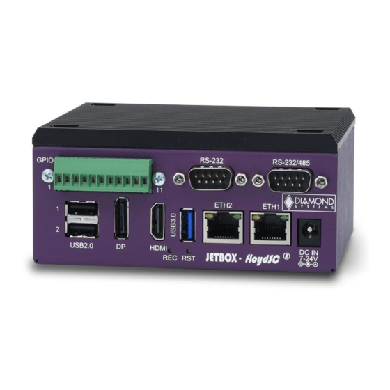
6. CONNECTORS, LEDS & JUMPER LOCATIONS JetBox-FloydSC Front Panel Call Outs Figure 5 JetBox-FloydSC - Front Panel Call-Outs Sl No Description Power In, 7 – 24 VDC Ethernet – 1 Ethernet – 2 Reset Switch Recovery Switch HDMI Port DP Port USB2.0 Digital I/O USB3.0... -
Page 11: Floydsc Carrier Board Callouts - Top
FloydSC Carrier board Callouts – TOP Figure 6 FloydSC Carrier Board – TOP FloydSC Carrier board Callouts – BOTTOM Figure 7 FloydSC Carrier Board - Bottom JetBox-FloydSC User Manual rev 0.1 www.diamondsystems.com Page 11... -
Page 12: Jumper Configuration
7. JUMPER CONFIGURATION NOTE: To access the jumpers on the Floyd baseboard, the TOP heat sink plate needs to be removed from the JetBox-FloydSC system. The various jumpers for the Jetbox-Floyd provided by the Floyd baseboard are as provided below: 1. -
Page 13: Usb2.0 Top Port Host/Device Selection
USB2.0 Top Port Host/Device Selection The USB2.0 Top port of the base board is used as a device in the recovery mode to flash the module and is used as a Host in normal operation. This selection is achieved by changing the jumper positions on JP3 as tabulated below: Jumper Position Configuration... -
Page 14: Connector Pinouts
8. CONNECTOR PINOUTS System Front Panel Connectors Input Power Connector The system provides a barrel connector for main input power. The connector has a 2.5mm center pin and is intended for use with mating connectors with 2.5mm inner diameter and 5.5mm outer diameter. Input voltage = +7V to +24V The connections for the power input connector are Tip = +V and Ring = -V. -
Page 15: Ethernet Ports
Ethernet Ports The ethernet ports are terminated on standard RJ45 connectors that has integrated LEDs. The connectors follow standard TIA/EIA 568B pinouts as below: Data A+ Orange/White Data A- Orange Data B+ Green / White Data C+ Blue Data C- Blue / White Data B- Green... -
Page 16: Serial Ports
Serial Ports The system provides two serial ports. One of the serial ports is dedicated to RS232 protocol and the second port can be configured to either RS232 or RS485 based on Jumper settings. The pinouts for different protocols are as follows: RS-232 RS-485... -
Page 17: Daughter Board Power Feed (J21)
Daughter Board Power Feed (J21) The connector is used to feed VIN input voltage from the Base Board to the Daughter Board when additional power is required for the Daughter Board. The pinouts for the optional Daughter Board Power feed connector are as shown below: Ground Ground... -
Page 18: Pcie Connector (J19)
M.2 PCIe Connector (J19) The FloydSC carrier board is equipped with an M.2 PCIe SSD M-keyed connector for 2280 0r 2242 sized modules for storage applications. An M.2 SSD is "keyed" to prevent the insertion of a card connector to an incompatible socket on the board. -
Page 19: Daughter Board Expansion Connector (J9)
Daughter Board Expansion Connector (J9) The FloydSC carrier supports additional interfaces using expansion connector for an optional daughter card. The pinouts of the Daughterboard Expansion connector are as below: Hi-Vin USB2_D_P Hi-Vin Hi-Vin USB_SS_TX_P Hi-Vin USB_SS_TX_N Hi-Vin Hi-Vin USB_SS_RX_P Hi-Vin USB_SS_RX_N Hi-Vin PCIe_RST#... -
Page 20: Controlled Area Network (J14)
Controlled Area Network (J14) Floyd SC model (FLDSC-BB02) implements one CAN bus controller port when integrated with Jetson Xavier NX module. The pinouts of the connector are as given below: Ground CAN Data - CAN Data + Ground Connector Part No: BM04B-GHS-TBT DSC Mating cable: 6981182 The CAN cable 6981182 has the near end terminated with the mating connector GHR-04V-S &... -
Page 21: I/O Connector List
9. I/O CONNECTOR LIST DSC Mating Function Manufacturer Part no. Description Cable Power In CUI Inc. PJ-202BH CONN PWR JACK 2.5X5.5MM SOLDER Daughter Board 0532610471 Molex CONN HEADER SMD R/A 4POS 1.25MM Power Feed RTC battery Molex 0022035025 CONN HEADER VERT 2POS 2.5MM 6980524 Molex 0533980471... -
Page 22: Digital I/O
10. DIGITAL I/O JetBox-FloydSC system provides 8 GPIOs exposed on the front panel on screw terminals. The pinout numbering of the screw terminals is as shown below: Figure 10 JetBox-FloydSC DIO Screw Terminal Pin Numbering The pinouts of the screw terminals are as given below: +3.3V DIO 0 DIO 1... -
Page 23: Digital I/O Specifications
Digital I/O Specifications The DIOs on Floyd SC are 3.3V/5V voltage selectable output compliant tolerant. The logic specifications are as follows: Device PCA9535 Number of Lines Direction Programmable bit by bit Logic Levels 3.3V/5V configurable Pull resistors 10K ohms +/-1%; Jumper-selectable pull-up/down Input Voltage Thresholds Logic 0 -0.5V min, 0.99V(3.3V VIO), 1.5V(5V VIO) max... -
Page 24: Digital I/O Control Software Commands
. Digital I/O Control Software Commands There are 4 commands to use the DIOs. They are as follows: 1. gpio_util setdir This command configures the direction of a particular DIO. For example, to set DIO 3 as an input & DIO 4 as an output, follow the command as provided below: gpio_util setdir 3 in;... -
Page 25: Serial Ports
11. SERIAL PORTS The serial ports on the Nano & Xavier NX are available at different device IDs. The device IDs are provided as below: NVIDIA Jetson Nano NVIDIA Jetson Xavier NX Serial Port 1 ttyTHS2 ttyTHS1 Serial Port 2 ttyTHS1 ttyTHS0 Protocol selection can be done by setting jumper configuration as per... -
Page 26: Getting Started
12. GETTING STARTED JetBox-FloydSC is shipped to our customers ready to work out of the box. A 12V DC adapter is included with the JetBox-FloydSC. The Jetson module, included with the JetBox-FloydSC is flashed with the latest BSP. However, it is highly recommended to check the Diamond System Corp website for any updated BSPs at http://www.diamondsystems.com/products/floydsc To get started with Jetbox-Floyd, a minimum of USB keyboard, USB mouse &... -
Page 27: System Assembly
13. SYSTEM ASSEMBLY Figure 12 JetBox-FloydSC System Assembly Components Sl No Description Quantity FloydSC PCB Jetson Module Flat Head M3 x 6mm Screws M3 x 8mm F/F Stand-offs Pan Head M3 x 6mm screws JetBox-FloydSC Internal Heat Spreader with Thermal Pad* Pan Head M2.5 x 10mm screws JetBox-FloydSC Top sink Thermal Pad DSC Cable# 6981330... -
Page 28: Installing The Jetson Module On Floydsc
JetBox-FloydSC assembly is basically split into two parts: 1. Installing the Jetson Module on FloydSC 2. Installing FloydSC inside the JetBox Installing the Jetson Module on FloydSC 5. If not present on board, install 4x M2.5 x 6.5mm long F/F spacers on board using 4x M2.5 x 4mm pan head screws inserted from the bottom. -
Page 29: Installing Floydsc Inside The Jetbox
Installing FloydSC inside the JetBox 1. Install 4x M3 x 8mm F/F stand-offs at location 4 inside the JetBox enclosure body by inserting 4x M3 x 6mm screws at location 3 from outside the enclosure on its bottom side. 2. Descend the FloydSC with Jetson module into the JetBox & align the board mounting holes with the F/F stand-offs installed at location 4 in the step above. -
Page 30: Reprogramming The Embedded Linux Image
4. Added utility for I2C GPIO expander 5. Added User LED control The Diamond Systems BSP is released as a compressed tar.gz file, that can be unzipped on an Ubuntu 10/04 Linux Host Machine and flashed onto the Jetson Nano and Xavier Modules. -
Page 31: Software Setup
Figure 16 Recovery Mode Terminal Screen Software Setup Follow the steps provided below corresponding to the installed module. Flashing Jetson Nano Module 1. Download the BSP Image file dsc-bsp-fsc-nano-release-2.0-20210707.tar.gz, from the FTP site and copy it to a directory on the Linux Host Machine. Alternatively, the file may be copied to a different source such as the Desktop. - Page 32 4. To flash the Jetson Nano module, issue the following command as depicted below: sudo ./flash.sh jetson-nano-emmc mmcblk0p1 Figure 17 Nano BSP Installation Initiation Module needs to be configured with user account first time. The user will be asked to enter few details to configure the OS.
-
Page 33: Flashing Jetson Xavier Nx Module
Flashing Jetson Xavier NX Module 1. Download the BSP Image file dsc-fsc-nx-release-2.0-20210707.tar.gz from the FTP site and copy it to a directory on the Linux Host Machine. Alternatively, the file may be copied to a different source such as the Desktop. 2. - Page 34 6. The flashing process will take 15-20 minutes to complete. The system will automatically Reboot when the flashing process is complete. Figure 20 Xavier NX BSP Installation Completion 7. Shutdown the carrier board and remove the recovery mode USB cable connection. 8.
-
Page 35: Specifications
15. SPECIFICATIONS Features Jetson Module Jetson Nano or Jetson Xavier NX Cooling Accessory Integrated heat spreader solution Display 1x HDMI 2.0a/b 1x Display Port 1.2a (Module Dependent) Camera Interface 3 x2 lane CSI-2 camera interfaces CAN Interface 1x CAN 2.0 Non-isolated transceiver standard, isolation optional consult factory (Module dependent) Digital I/O 8x Digital IOs obtained through I2C GPIO expander... -
Page 36: Limited Warranty Policy
16. LIMITED WARRANTY POLICY Diamond Systems Corporation warrants that its products will be free from defects and errors in material and workmanship and perform in full accordance with the technical specifications stated in the description of the product for a 2-Year Period from the Date of Shipment.
Need help?
Do you have a question about the JETBOX FLOYD-SC Series and is the answer not in the manual?
Questions and answers