Table of Contents
Advertisement
Quick Links
Carrier for NVIDIA
Revision No
Release Date
1.01
08/05/2019
1.02
01/14/2020
1.03
01/26/2020
1.04
03/27/2020
FOR TECHNICAL SUPPORT
PLEASE CONTACT:
Email:
support@diamondsystems.com
ELTON™
®
AGX Xavier Module
USER MANUAL
Comments
Initial Release
Major Feature Updates
Added Sections: PC/10, DAQ, and Getting Started
Added Addendum
© Copyright 2020
Diamond Systems Corporation
www.diamondsystems.com
Advertisement
Table of Contents

Subscribe to Our Youtube Channel
Related Manuals for Diamond Systems ELTON ELT-BB01


Summary of Contents for Diamond Systems ELTON ELT-BB01
- Page 1 Revision No Release Date Comments 1.01 08/05/2019 Initial Release 1.02 01/14/2020 Major Feature Updates 1.03 01/26/2020 Added Sections: PC/10, DAQ, and Getting Started 1.04 03/27/2020 Added Addendum FOR TECHNICAL SUPPORT PLEASE CONTACT: © Copyright 2020 Diamond Systems Corporation Email: support@diamondsystems.com www.diamondsystems.com...
-
Page 2: Table Of Contents
Contents Important Safe Handling Information ......................4 Introduction ...............................6 Elton Baseboard Overview ..........................6 Elton Baseboard Models ..........................7 AGX Xavier Modules Overview ........................7 Functional Overview ............................9 Processor Modules ............................9 Power Supply Specifications .........................9 Backup Battery ..............................9 Ethernet Ports ............................. 10 Display Controller ............................10 Camera Serial Interface (CSI) ........................ - Page 3 11. PC/104 Expansion System ..........................35 Overview ..............................35 Functional Block Diagram ........................... 36 PC/104 Bus Framework ..........................36 PCIe/104 Type 1 and Type 2 Standards ....................37 PCI/104-Express Version 1.0 and 1.1 Host Board Compatibility ............... 38 PCI/104-Express Version 1.0 and 1.1 Peripheral Board Compatibility ............38 PCIe/104 Features .............................
-
Page 4: Important Safe Handling Information
Diamond Systems recommends that all its boards be stored only in individual ESD-safe packaging units. If multiple boards are stored together, they should be contained in bins with dividers placed between the boards. - Page 5 Overvoltage on Analog Input: If a voltage applied to an analog input exceeds the power specification of the board, the input multiplexer and/or parts behind it can be damaged. Most Diamond Systems boards will withstand an erroneous connection of up to 36V on the analog inputs, even when the board is powered off, but not on all boards, and not under all conditions.
-
Page 6: Introduction
2. INTRODUCTION Elton Baseboard Overview The Elton baseboard is the latest product from Diamond Systems to integrate the newly-released Standalone NVIDIA AGX Xavier System on Module (SoM) Series: AGX Xavier AGX Xavier 8 GB NOTE: Currently the Elton Board Support Package (BSP) supports the AGX Xavier Module Series only. -
Page 7: Elton Baseboard Models
Operating System Support Linux Kernel version 4.4.38; Ubuntu 16.04 AArch64 Mechanical, Electrical, and Environmental Properties H 6” x W 4” (152.4 mm x 101.6 mm) Form-Factor Cooling Mechanism Conduction Cooling Power Input Range +9V to +20V Operating Temperature -25°C to +80°C Ambient Range Elton Baseboard Models Elton baseboard variants offer a complete modular platform in compliance with requisite specifications that... - Page 8 AGX Xavier Series Feature Description Feature Description AGX XAVIER AGX XAVIER 8 GB 512-core NVIDIA Volta™ GPU 384-core NVIDIA Volta™ GPU with Tensor Cores with Tensor Cores (2x) NVIDIA Deep Learning Accelerator (2x) NVIDIA (NVDLA) Engines DL Accelerator (NVDLA) Engines 8-core ARMv8.2 @ 64-bit CPU, 6-core Arm®v8.2 64-bit CPU, 8 MB L2 + 4 MB L3...
-
Page 9: Functional Overview
3. FUNCTIONAL OVERVIEW The following section provides functional details of the key sub-systems implemented on the baseboard. Processor Modules The baseboard currently supports the Jetson™ Series AGX Xavier Modules. Both series, the AGX Xavier and Xavier 8 GB Modules integrate 512-core NVIDIA Volta GPU with Tensor Cores, and offer 16 GB of 256-bit LPDDR4x memory with 137 GB/s of bandwidth at 2133 MHz bus speeds that enable AI-powered platform tools to process high resolution computing tasks at 20 to 32 Tera Operations Per Second (TOPS) respectively. -
Page 10: Ethernet Ports
KSZ9031 PHY from Microchip. Each Port is equipped with on-board magnetics and 2x5 headers that are compatible with Diamond Systems standard Ethernet cables. On-board LEDs are available to indicate the Link, Activity, and Speed status associated with each port. The LEDs are located along the board edge near the Ethernet connectors. -
Page 11: Audio Interface
Audio Interface The Audio Chip, Part Number SGTL5000 provides audio support on the baseboard. Audio I/O signals are generated through a 2mm header and include the following features: Stereo Line-Out Mic-In The AGX Xavier Series Module implements a High Definition Audio (HDA) controller. The controller provides a multi-channel audio path to the HDMI (High-Definition Multimedia Interface) interface. - Page 12 The USB 3.0 device controller enables the AGX Xavier Series Module to be accessed from an external Host device. The controller supports USB 2.0 or USB 3.0 with up to 15 IN and 15 OUT Endpoints, which can be configured to support transfer types of different input devices such as a modem or a storage drive. Both, the xHCI and USB 3.0 device controllers support USB Link Power Management (LPM) features: Remote Wakeup Wake On Connect...
-
Page 13: Pcie Minicard Socket
PCIe MiniCard Socket The baseboard is equipped with one Mini PCIe Socket that supports full-size modules. Two threaded spacers are mounted on the board for installing a full-size module. A USB 2.0 interface is provided for plugging-in additional cards for expansion and connectivity. The USB 2.0 port is shared between Skywire™... -
Page 14: Controller Area Network (Can) Interface
Controller Area Network (CAN) Interface The AGX Xavier Series Module integrate two independent CAN ports/channels which support connectivity to two CAN networks. The CAN interfaces are routed to the baseboard via a 4-Pin Miniature 1.25mm Pitch latching connectors. TJA1050T CAN Transceiver interfaces between the CAN protocol controller and the physical bus. It enables high-speed automotive applications using baud rates from 60 Kbaud up to 1 Mbaud and provides differential transmission capabilities to the bus and differential receiver capabilities to the CAN protocol controller. -
Page 15: Functional Block Diagram
4. FUNCTIONAL BLOCK DIAGRAM Elton Baseboard Block Diagram The following block diagram illustrates the key functional blocks of the Elton baseboard with integrated NVIDIA AGX Xavier Series Module and PCI/104 Express 3-Bank Expansion components. Figure 4.1-1: Baseboard Functional Block Diagram Elton User Manual Rev 1.04 www.diamondsystems.com Page 15... -
Page 16: Agx Xavier Series Module Block Diagram
AGX Xavier Series Module Block Diagram The following block diagram illustrates a high-level view of the AGX Xavier Series components. The ports are broken out through the carrier board. Figure 4.2-1: AGX Xavier Series Module Functional Block Diagram Elton User Manual Rev 1.04 www.diamondsystems.com Page 16... -
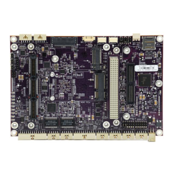
Page 17: Mechanical Drawing
5. MECHANICAL DRAWING Figure 5-1 illustrates the mechanical top view of the Elton baseboard. Figure 5-1: Elton Baseboard Mechanical Top View Elton User Manual Rev 1.04 www.diamondsystems.com Page 17... -
Page 18: Connector And Jumper Location
6. CONNECTOR AND JUMPER LOCATION Figure 6-1 displays the top and bottom layout views of the Elton baseboard. A description of the Jumpers and Connectors is tabulated below. Figure 6-1: Baseboard Jumper and Connector Layout Top View Elton User Manual Rev 1.04 www.diamondsystems.com Page 18... - Page 19 Figure 6-2 displays the bottom layout view of the Elton baseboard. A description of the Jumpers and Connectors is tabulated below. Figure 6-2: Baseboard Jumper and Connector Layout Bottom View Elton User Manual Rev 1.04 www.diamondsystems.com Page 19...
-
Page 20: I/O Connectors, Jumpers And Led Specifications
7. I/O CONNECTORS, JUMPERS AND LED SPECIFICATIONS The following table delineates the I/O connectors, Jumpers, and LED Block functions, marked in Figure 6-1. Figure 6-2. Connector Function Jumper Function PCIe/104 LVDS_BKLT, LVDS_VDD, VIO_PCI PCI-104 Serial Termination, USB Host, LTE USB Selection USB 3.1 Serial Termination, PCI Power Disable LED Block... -
Page 21: Connector Pinout Specifications
8. CONNECTOR PINOUT SPECIFICATIONS Power IN Connector: J16 The Power-IN connector supplies power using an input voltage range from +9V to +20V. NOTE: The AGX Xavier Series Module is not hot-pluggable. Before installing or removing the module, the main power supply pins must be disconnected and the recommended wait-time of 1-minute must be allowed for the various power rails to fully discharge. -
Page 22: Audio Signal Connector: J13
Audio Signal Connector: J13 The audio signal interface implements audio-port switching functionality with digital microphone and speaker outputs. The audio signals are terminated at the 2x5 header with the following pinouts. NOTE: The Line-In feature is not supported by the Elton BSP (Board Support Package). LineOut-L A01 B01 LineOut-R GND_Audio A02 B02 GND_Audio LineIn-L A03 B03 LineIn-R... -
Page 23: Lvds Lcd Connector: J7
LVDS LCD Connector: J7 The Low-Voltage Differential Signaling (LVDS) LCD connector interface defines the physical layer parameters for differential, serial communication protocols and is used in conjunction with a data link layer. It operates on low power and performs at high speeds. The pinouts for the LVDS-LCD connector are specified below. -
Page 24: Usb 2.0 Port Connector: J20
USB 2.0 Port Connector: J20 The baseboard hosts two USB 2.0 ports The USB 2.0 interface connector features data and power pins on a pin header. The shield pin is tied to the Chassis Ground. The pinouts for the USB 2.0 connector are specified below. Key A01 B01 Shield USB1 Pwr- A02 B02 USB0 Pwr- USB1 Data+ A03 B03 USB0 Data+... -
Page 25: Pci-104 Connector: J2
PCI-104 Connector: J2 The baseboard contains a non-stack-through/short pin PCI-104 connector located on top of the board in the standard position, as specified in the PC/104-Plus Specifications. The J3 connector pinouts are specified below. GND/5.0V KEY Reserved AD00 VI/O AD02 AD01 AD05 AD04... -
Page 26: Camera Expansion Connector: J12
Camera Expansion Connector: J12 The AGX Xavier Series Module embeds a 2x60 expansion socket header for camera installation. The interface includes options for multiple cameras and audio signals. The 4x4 CSI lanes from the AGX Xavier Series Module terminate at the 60x2 header. The pinouts for the connector are specified below. -
Page 27: Serial Port Connectors: J22, J23
Serial Port Connectors: J22, J23 The Elton baseboard supports four serial ports available at two headers. Each connector supports two serial ports. The pinouts specific to transceiver interfaces RS232/ RS422/ RS485 are specified below. RS-232 Interface TX1 A01 B01 RTS1 RX1 A02 B02 CTS1 GND A03 B03 GND TX2 A04 B04 RTS2... -
Page 28: Usb 3.1 Port Connectors: J3, J21
USB 3.1 Port Connectors: J3, J21 Two USB 3.0/3.1 connectors are available on the baseboard. Both are routed from the AGX Xavier Series Module to the 2x5 Header. The shield pin is tied to the Chassis Ground. The pinouts for the connector are specified below. USB_SSRX0- A01 B01 Shield USB_SSRX0+ A02 B02 USB1 Pwr- USB1 Pwr- A03 B03 USB2.0 Data+... -
Page 29: Pcie Ssd Socket (M-Key) Connector: J9
M.2 PCIe SSD Socket (M-KEY) Connector: J9 The Elton baseboard is equipped with an M-keyed connector. An M.2 SSD is "keyed" to prevent the insertion of a card connector to an incompatible socket on the host. There are three keys that are commonly used: B, M, and B+M with the key type typically labeled on or near the edge of the gold-plated fingers on the connector of the SSD. -
Page 30: Data Acquisition (Daq) Connector: J24
Data Acquisition (DAQ) Connector: J24 The baseboard implements a multifunction Digital I/O circuit that integrates analog input and output, digital input and output, and counter/timer functionalities. The pinouts for the connector specified below. AIN1 / 0+ AIN0 / 0- A01 AIN3 / 1+ AIN2 / 1- A02 AIN4 / 2- A03... -
Page 31: Can Connectors: J5, J6
CAN Connectors: J5, J6 There are two identical on-board CAN interface connectors that are routed from the AGX Xavier Series Module. The pinouts are specified below. Ground CAN Low CAN High Ground Connector Type: 1.25mm Single Row SMD RA Cable Part Number: 6981182 UFS Interface Connector: J15 The AGX Xavier Series Module supports a x1 lane UFS interface. -
Page 32: I/O Connector List
9. I/O CONNECTOR LIST The following table provides a summary of the I/O connectors on the Elton baseboard. Function Manufacturer Part No. Description Mating Cable Power IN Samtec IPL1-102-01-D-RA-K 2x2 Box Header T/H Right Angle .1 Pitch 6981507 External 2 Pos. TH VERT RA HDR, 2.5 MM Molex 22-035-5025 6980524... -
Page 33: Jetson Xavier B2B Connector Interface
10. JETSON XAVIER B2B CONNECTOR INTERFACE The following table figure depicts Jetson AGX Xavier Series Module Connector Pin Out Matrix Part 1: Columns A – F. Elton User Manual Rev 1.04 www.diamondsystems.com Page 33... - Page 34 The following table figure depicts Jetson AGX Xavier Series Module Connector Pin Out Matrix Part 2: Columns G – L. Elton User Manual Rev 1.04 www.diamondsystems.com Page 34...
-
Page 35: Pc/104 Expansion System
11. PC/104 EXPANSION SYSTEM Overview Elton baseboard embeds the PC/104 Expansion Module that integrates PCI and PCIe connectors in a compact-sized form-factor measuring approximately 3.6" x 3.8" (90mm x 96mm). The PCI Express (Peripheral Component Interconnect Express/PCIe) architecture improvises on the conventional PCI bus configurations to deliver the next generation PC/104 high-speed serial bus expansion system, implemented by a pair of surface mount connectors in a slot-oriented platform that incorporates a non-conventional point-to-point interface technology, while still retaining compatibility within the conventional... -
Page 36: Functional Block Diagram
Functional Block Diagram The following block diagram illustrates the functional blocks of the PC/104 Module interconnected with NVIDIA AGX Xavier Series Module, PCI/104 Express 3-Bank expansion components, and the expansion PCI bus connector. Figure 11.1-1: PC/104 Express Block Diagram PC/104 Bus Framework The PC/104 Consortium specifications framework encapsulate standards related to ISA, PCI, and PCI Express buses used in a PC. -
Page 37: Pcie/104 Type 1 And Type 2 Standards
The following schematic represents the PC/104 120-pin expansion bus connector and dimensions. Figure 11.2-1: PC/104 Expansion Bus Connector Dimensions PCI/104-Express Bus The PCI/104-Express specification incorporates the PCI Express bus (PCIe) in addition to the previous- generation PCI bus. The specification defines a 156-pin surface mount connector for the PCI Express signals. -
Page 38: Pci/104-Express Version 1.0 And 1.1 Host Board Compatibility
The following table summarizes the comparison between Type 1 and Type 2 features of the module. Feature Type 1 Type 2 OneBank USB 2.0 PCIe x 1 Power +3.3V, +5V, +12V +3.3V, +5V, +12V +3.3V, +5V ATX Control PCIe x 4 PCIe x 16 NOTE: x16 Link can be used as x8 or x4. -
Page 39: Pci/104-Express Features
PCI/104-Express Features Connector A: Accommodates all the features listed under Connector A: PCI Express Bus Connector B: High-Reliability Rugged Stacking Expansion Bus PC/104 expansion modules can be mounted directly to the PC/104 bus connector. Stacking connectors on the module, implement expansion buses for plugging boards vertically, empowering users to build modular embedded systems from board-level components. -
Page 40: Pcie/104 Onebank And Pci Express Connector
The following table provides a summary of the PCI Express versions and their respective data transfer specifications. PCI Express Transfer rate Bandwidth Version Gigatransfers Per Lane X16 Lane Slot Per Second 4 Gbit/s (500 MB/s) 32 Gbit/s (4 GB/s) 2.5 GT/s 2 Gbit/s (250 MB/s) 4 Gbit/s (500 MB/s) 64 Gbit/s (8 GB/s) -
Page 41: Pcie/104 3-Bank Pci Express Connector
PCIe/104 3-Bank PCI Express Connector The standard PCIe/104 bus is designed for maximum bus feature functionality through a 152-pin 3-Bank connector which is classified as Type 1 or Type 2. Both Type 1 and Type 2 share a common feature set and pin assignments which include: Four x1 PCI Express Links, Two USB 2.0, ATX Power and Control signals: +5V Standby, Power supply on, Power Good, Power: +3.3V, +5V, +12V, and SMBus. -
Page 42: Jumper Description
12. JUMPER DESCRIPTION The Jumper blocks on the Elton baseboard can be configured to enable/disable or alter the default signal routing settings on the circuit, using Jumper shunts. The following table describes the Jumper Blocks on the baseboard. Refer to Figure 6-1 for Jumper Locations. -
Page 43: Serial Termination And Usb Mode Selection: Jp2
Serial Termination and USB Mode Selection: JP2 The JP2 block settings can be switched/shorted to operate in different modes. The mode is selected using Jumper shunts. The options in JP2 enable switching for the120ohm terminator resistor in the RS422/485 interface and the USB 2.0 ports. The first four positions of the Jumper are used to select the termination points for serial ports 1 and 2 in the RS422/RS485 mode. -
Page 44: Serial Termination Debug Uart And Pcie/104 Power: Jp3
Serial Termination Debug UART and PCIe/104 Power: JP3 The JP3 block settings can be switched to operate in different modes. Serial Port 3 and Serial Port 4 TX Termination Serial Port 3 and Serial Port 4 RX Termination ... -
Page 45: Getting Started
NOTE: The AGX Xavier Series Module must be programmed with the Diamond System Image file for the interfaces on the Elton baseboard to be operational. Diamond Systems Image is released as a compressed tar.gz file, that can be unzipped on a Linux Host Machine and flashed on to the AGX Xavier Series Module. - Page 46 NOTE: The sequence of images represented in this section have been captured from the Linux Host PC. elton-release-0.1-20190627.tar.gz 4. Download the Elton baseboard Image file file, from the FTP (File Transfer Protocol) site and copy it to the Linux Host Machine. Figure 13.1-2: Elton Release Image File Displayed on Screen To unzip the copied Image file: 5.
- Page 47 The Terminal will display the NVIDIA device listed under USB devices as shown below. Figure 13.1-5: Device Detected on NVidia USB Bus Screen To flash the AGX Xavier Series Module: Type and Enter the following: sudo ./flash.sh jetson-xavier-maxn mmcblk0p1 The flashing process will take 15-20 minutes to complete. NOTE: Do not interrupt or interfere with the USB connectivity or the power supply to Elton until the flashing procedure is complete.
-
Page 48: Data Acquisition (Daq) Subsystem
Ground pins 9 and 10, and all digital I/O signals must be referenced to the digital Ground pins 11 and 26. A standard 2x13 2mm pitch ribbon cable connector or Diamond Systems non-latching cable No. 6980516 or latching cable No.6980606 can be plugged into the connector. - Page 49 Although the native A/D resolution is 12-bits, the SAM microcontroller contains an innovative feature that enables higher resolution by averaging several samples. This technique enables the resolution to be configured to 16-bits. Oversampling and averaging can be used to: Increase measurement resolution. ...
- Page 50 All A/D circuits are susceptible to inherent gain and offset errors depending upon factors such as temperature. The SAM circuit calibrates some of these errors to provide better accuracy. The Diamond Systems driver and Programming Library calibrate raw uncorrected data or corrected data with greater accuracy between the A/D input range of 0V and/or 3.3V.
-
Page 51: Analog Outputs
Analog Outputs Analog Output sensors convert digital values into analog voltages or current signals that can be analyzed and controlled. A single-ended output is a signal that is always referenced to the shield -which is typically earth Ground, on the output connector. The voltage should be measured in proportion to the analog Ground pins. The two analog outputs feature a 12-bit resolution and single-ended 0-3.3V output range. -
Page 52: Digital I/O Operations
Digital I/O Operations The DAQ circuit contains 13 digital I/O (GPIO) lines with 3.3V logic levels. During power-up or reset, all I/O lines are programmed to input direction to avoid any conflicts with external circuitry. Each digital I/O line can be individually configured to set the input or output direction. This enables the lines to split between input and output. - Page 53 Table 14-1: I/O Signal Mapping SAM Pin No. SAM Pin Name DAQ Function ADC0 / ADC0- PA04 / ADC0_AIN4 ADC1 / ADC0+ PB09 / ADC0_AIN3 PB08 / ADC0_AIN2 ADC2 / ADC1- ADC3 / ADC1+ PA07 / ADC0_AIN7 ADC4 / ADC2- PA06 / ADC0_AIN6 ADC5 / ADC2+ PB03 / ADC0_AIN15...
-
Page 54: Thermal Solutions
15. THERMAL SOLUTIONS The Elton baseboard implements an optimized Thermal Management System to ensure that the baseboard and components are maintained at their maximum specified temperatures. Applying a thermal management component below recommended standards will produce undesirable consequences. The baseboard is designed to operate at a temperature range of-40°C to +85°C, while the AGX Xavier Series Module operates at a temperature range of -25°C to +80°C. -
Page 55: Baseboard Heat Spreader Specifications
Baseboard Heat Spreader Specifications Elton baseboard accommodates a Heat Spreader that transfers energy from the hotter source to a heat sink or heat exchanger and contains high thermal conductivity. It is designed to dissipate heat effectively for optimal thermal performance and optimize performance while maintaining the baseboard rated temperature. The Heat Spreader material is manufactured under high temperature and high-pressure sintering of particles to form a lattice structure that is placed intermediate between heat spreading materials. - Page 56 The following image illustrates the Outer and Inner Mounting Holes on the baseboard and for the AGX Xavier Series Module Thermal Accessory. Figure 15.1-2: Schematic Top View Section with Mounting Hole Specifications The following image depicts the baseboard with the Heat Spreader installed. Figure 15.1-3: Baseboard with Heat Spreader Plate Installed Elton User Manual Rev 1.04 www.diamondsystems.com...
-
Page 57: Specifications
16. SPECIFICATIONS The Elton baseboard Specifications are summarized in the following table. Feature Module AGX Xavier Series 8-Core ARM v8.2 64-Bit CPU, 8 MB L2 + 4 MB L3 Cooling Accessory Heat Spreader 1 6GB 256-bit LPDDR4x; 2133MHz – 137 MBGB/s SDRAM Memory Display Three Multi-Mode DP 1.2/eDP 1.4/HDMI 2.0... -
Page 58: Addendum
17. ADDENDUM The following section provides additional information and instructions relevant to the components specified in the Main Sections of this document. Programming NXP PTN3460 Chip NOTE: Conventionally, the PTN3460 chip is packaged pre-programmed by the integrated circuit manufacturer. The following instructions have been provided as an additional resource. The LVDS interface can be configured using multi-level configuration pins (CFG1, CFG2, CFG3, and CFG4) or through the Register interface. - Page 59 The following Read and Write commands enable the user to access and control data that is stored in registers. In order to transact write byte/read byte, the register must be specified. The GPIOs for PTN3460 can be programmed through i2c communication bus connected to the Xavier Series Module as described in the parameters below.
- Page 60 The image below depicts the screen dump of a programmed PTN for M215HTN01.1 LCD with dual-channel at 1920x1080 resolution. Figure 17.1-1: Screen Dump PTN for M215HTN01.1 LCD Display with Dual Channel The registers for Read and Write operations for the LVDS bridge IC PTN3460 device and the baseboard are addressable at a range of Type Values 0x80-0x8F.
-
Page 61: Camera Installation Procedures
When the Flashing process is complete: Power cycle the system and verify that the PTN3460 chip has retained the written values. Set the GPIO to high-level mode. Refer to Section 17.1 Programming NXP PTN3460 Chip for scripting instructions on setting the GPIO to high-level mode. - Page 62 2. The Adaptor Board : 3. The Dual Board e-CAM130_TRICUTX2_ADAPTOR e-CAM137_CUMI1335_MOD 1. Insert the e-CAM130_CUXVR board CN1 connector to the camera connector on the Elton baseboard. Refer to Section 6: Connector And Jumper Location. for the location of the camera connector.
- Page 63 An image of the 4-camera installation is depicted below. 6. Power-on the system. NOTE: For a successful implementation ensure that the trigger signal range conforms to 3.3V or 5V. A voltage signal greater than 5V will cause permanent damage to the chip. The synchronous mode is a special feature of the e-CAM130_CUXVR board that synchronizes all the captured camera frames according to the integrated PWM pulse within the trigger functionality.
-
Page 64: Serial Multiprotocol Configuration
When the command is executed the following screen will be displayed. 9. To end the streaming process, press Ctrl + C on the keyboard. 10. Enter the following command line to switch or change the parameters of the specific camera (1, 2, 3, or 4 respectively. -
Page 65: Can Controller Configuration
RS485_util provides the option to enable or disable RS485/422 direction control on the UART ports. RS485_util NOTE: The must be run after the ports are opened. Running the utility before the ports are open may result in the Terminal utility resetting the flag settings. Before transmitting, set the mode for individual ports.by replacing the parameter with the port number as shown the syntax below. -
Page 66: Limited Warranty Policy
18. LIMITED WARRANTY POLICY Diamond Systems Corporation warrants that its products will be free from defects and errors in material and workmanship and perform in full accordance with the technical specifications stated in the description of the product for a 2-Year Period from the Date of Shipment.
Need help?
Do you have a question about the ELTON ELT-BB01 and is the answer not in the manual?
Questions and answers