Table of Contents
Advertisement
Advertisement
Table of Contents

Related Manuals for Mitsubishi FR-E520-0.1KN


Summary of Contents for Mitsubishi FR-E520-0.1KN
- Page 1 TRANSISTORIZED INVERTER FR-E INSTRUCTION MANUAL HIGH PERFORMANCE & HIGH FUNCTION FR-E520-0.1KN to 7.5K-KN OUTLINE Chapter 1 INSTALLATION Chapter 2 AND WIRING OPERATION/ Chapter 3 CONTROL PARAMETERS Chapter 4 PROTECTIVE Chapter 5 FUNCTIONS SPECIFICATIONS Chapter 6...
- Page 2 Thank you for choosing the Mitsubishi Transistorized inverter. This instruction manual gives handling information and precautions for use of this equipment. Incorrect handling might cause an unexpected fault. Before using the inverter, please read this manual carefully to use the equipment to its optimum.
- Page 3 SAFETY INSTRUCTIONS 1. Electric Shock Prevention WARNING ! While power is on or when the inverter is running, do not open the front cover. You may get an electric shock. ! Do not run the inverter with the front cover removed. Otherwise, you may access the exposed high-voltage terminals or the charging part of the circuitry and get an electric shock.
- Page 4 3. Injury Prevention CAUTION ! Apply only the voltage specified in the instruction manual to each terminal to prevent damage etc. ! Ensure that the cables are connected to the correct terminals. Otherwise, damage etc. may occur. ! Always make sure that polarity is correct to prevent damage etc. ! While power is on and for some time after power-off, do not touch the inverter or brake resistor as they are hot and you may get burnt.
- Page 5 ( 2 ) Wiring CAUTION ! Do not fit capacitive equipment such as a power factor correction capacitor, noise filter or surge suppressor to the output of the inverter. ! The connection orientation of the output cables U, V, W to the motor will affect the direction of rotation of the motor.
- Page 6 CAUTION ! The electronic overcurrent protection does not guarantee protection of the motor from overheating. ! Do not use a magnetic contactor on the inverter input for frequent starting/stopping of the inverter. ! Use a noise filter to reduce the effect of electromagnetic interference. Otherwise nearby electronic equipment may be affected.
-
Page 7: Table Of Contents
CONTENTS 1 OUTLINE 1.1 Pre-Operation Information ..................1 1.1.1 Precautions for operation ..................1 1.2 Basic Configuration.....................3 1.2.1 Basic configuration ....................3 1.3 Structure ........................4 1.3.1 Appearance and structure ..................4 1.3.2 Functions......................5 1.3.3 Inverter communication specifications..............5 1.3.4 Communication with remote devices..............5 1.3.5 Removal and reinstallation of the front cover ............6 1.3.6 Removal and reinstallation of the wiring cover .............7 1.3.7 Removal and reinstallation of the accessory cover ..........8 1.3.8 Exploded view ......................9... - Page 8 2.3.7 Instructions for compliance with the European standards ........45 3 OPERATON/CONTROL 3.1 Inverter Setting......................47 3.1.1 Pre-operation checks ..................47 3.1.2 Inverter station number setting ................48 3.1.3 Setting of the transmission baudrate setting switch ...........49 3.1.4 Power on ......................49 3.1.5 Confirmation of the operation mode ..............50 3.2 Function Overview ....................51 3.2.1 Function Block Diagram ..................51 3.2.2 Function overview....................52...
- Page 9 4.2.1 Torque boost (Pr. 0, Pr. 46)................76 4.2.2 Output frequency range (Pr. 1, Pr. 2, Pr. 18)............77 4.2.3 Base frequency, base frequency voltage (Pr. 3, Pr. 19, Pr. 47) ......78 4.2.4 Multi-speed operation (Pr. 4, Pr. 5, Pr. 6, Pr. 24 to Pr. 27, Pr. 232 to Pr. 239) ..79 4.2.5 Acceleration time (Pr.
- Page 10 4.2.36 Output (remote input) function selection (Pr. 190 to Pr. 192) ......132 4.2.37 Cooling fan operation selection (Pr. 244) ............133 4.2.38 Slip compensation (Pr. 245 to Pr. 247) ............134 4.2.39 Ground fault detection at start (Pr. 249) ............135 4.2.40 Stop selection (Pr. 250)..................136 4.2.41 Communication error "E.OPT"...
- Page 11 6 SPECIFICATIONS 6.1 Standard Specifications ..................164 6.1.1 Model specifications ..................164 6.1.2 Common specifications ..................165 6.1.3 Outline dimension drawings ................167 APPENDIX APPENDIX 1 Data Code List ..................171...
- Page 12 1.2 Basic Configuration............. 3 1.3 Structure ..............4 Chapter 2 <Abbreviations and generic names> ! PU Parameter unit (FR-PU04) ! Inverter Chapter 3 Mitsubishi transistorized inverter FR-E500 series ! Pr. Parameter number ! CC-Link Chapter 4 Control & Communication Link Chapter 5...
-
Page 13: Outline
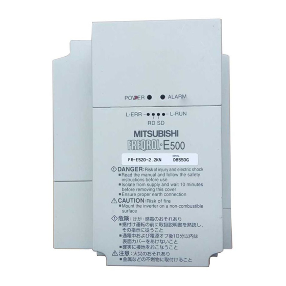
1) Inverter type Capacity plate Rating plate MITSUBISHI Rating plate INVERTER MODEL FR-E520-0.1KN Inverter type Capacity plate Input rating INPUT XXXXX FR-E520-0.1KN/ Output rating OUTPUT :... - Page 14 OUTLINE ( 2 ) Preparation of instruments and parts required for operation Instruments and parts to be prepared depend on how the inverter is operated. Prepare equipment and parts as necessary. (Refer to page 47.) ( 3 ) Installation To operate the inverter with high performance for a long time, install the inverter in a proper place, in the correct direction, with proper clearances.
-
Page 15: Basic Configuration
1.2 Basic Configuration OUTLINE 1.2 Basic Configuration 1.2.1 Basic configuration The following devices are required to operate the inverter. Proper peripheral devices must be selected and correct connections made to ensure proper operation. Incorrect system configuration and connections can cause the inverter to operate improperly, its life to be reduced considerably, and in the worst case, the inverter to be damaged. -
Page 16: Structure
1.3 Structure OUTLINE 1.3 Structure 1.3.1 Appearance and structure (1) Front view POWER lamp (yellow) Accessory cover ALARM lamp (red) Operating status indicator LEDs Rating plate Front cover Capacity plate Wiring cover (2) Without accessory cover and front cover PU connector* POWER lamp (yellow) ALARM lamp (red) Control circuit terminal block... -
Page 17: Functions
OUTLINE 1.3.2 Functions Name Function Station number setting Used to set the inverter station number switches between 1 and 64. For details, refer to page 48. ×10 ×1 Transmission baud Switch used to set the transmission speed. rate setting switch For details, refer to page 49. -
Page 18: Removal And Reinstallation Of The
1.3.5 Removal and reinstallation of the front cover " " " " Removal (For the FR-E520-0.1KN to 3.7KN) The front cover is secured by catches in positions A and B as shown below. Push either A or B in the direction of arrows, and using the other end as a support, pull the front cover toward you to remove. -
Page 19: Removal And Reinstallation Of The Wiring Cover
OUTLINE Note: 1. Make sure that the front cover has been reinstalled securely. 2. The same serial number is printed on the capacity plate of the front cover and the rating plate of the inverter. Before reinstalling the front cover, check the serial numbers to ensure that the cover removed is reinstalled to the inverter from where it was removed. -
Page 20: Removal And Reinstallation Of The Accessory Cover
OUTLINE 1.3.7 Removal and reinstallation of the accessory cover " " " " Removal Hold down the portion A indicated by the arrow and lift the right hand side using the portion B indicated by the arrow as a support, and pull out the accessory cover to the right. -
Page 21: Exploded View
OUTLINE 1.3.8 Exploded view... - Page 22 C H A P T E R 2 CHAPTER 2 INSTALLATIONAND INSTALLATION AND WIRING WIRING This chapter gives information on the basic "installation and wiring" for use of this product. Always read the instructions in this chapter before using the equipment.
-
Page 23: Installation And Wiring
2 INSTALLATION AND WIRING 2.1 Installation 2.1.1 Instructions for installation When mounting any of the FR-E520-0.1KN to 0.75KN, remove the accessory cover, front cover and wiring cover. 1) Handle the unit carefully. The inverter uses plastic parts. Handle it gently to protect it from damage. - Page 24 INSTALLATION AND WIRING 7) Note the cooling method when the inverter is installed in an enclosure. When two or more inverters are installed or a ventilation fan is mounted in an enclosure, the inverters and ventilation fan must be installed in proper positions with extreme care taken to keep the ambient temperatures of the inverters with the permissible values.
-
Page 25: Wiring
2.2 Wiring INSTALLATION AND WIRING 2.2 Wiring 2.2.1 Terminal connection diagram " " " " 3-phase 200V power input Motor 3-phase AC power supply Ground Jumper Output stop Remove this jumper when (+)P Reset using the optional power-factor improving DC reactor. Sink input (Note 2) (−)N... - Page 26 INSTALLATION AND WIRING ( 1 ) Description of the main circuit terminals Symbol Terminal Name Description R, S, T Connect to the commercial power supply. Keep these terminals AC power input unconnected when using the high power factor converter. U, V, W Inverter output Connect a three-phase squirrel-cage motor.
- Page 27 INSTALLATION AND WIRING ( 3 ) CC-Link communication signals Terminal Symbol Terminal Name Description CC-Link Connected with the master station and other local stations to make communication CC-Link communication. signals ( 4 ) RS-485 communication Name Description Communication can be made by the PU connector in accordance with RS-485. ! Compliant standard: EIA Standard RS-485 ! Transmission form: Multidrop link system PU connector...
-
Page 28: Wiring Of The Main Circuit
INSTALLATION AND WIRING 2.2.2 Wiring of the Main Circuit ( 1 ) Wiring instructions 1) It is recommended to use insulation-sleeved solderless terminals for power supply and motor wiring. 2) Power must not be applied to the output terminals (U, V, W) of the inverter. Otherwise the inverter will be damaged. - Page 29 INSTALLATION AND WIRING 6) Connect only the recommended optional brake resistor between the terminals P-PR (+-PR). Keep terminals P-PR (+-PR) of 0.1K or 0.2K open. These terminals must not be shorted. 0.1K and 0.2K do not accept the brake resistor. Keep terminals P-PR (+-PR) open. Also, never short these terminals.
- Page 30 The following table lists the cables and crimping terminals used with the inputs (R (L S (L ), T (L )) and outputs (U, V, W) of the inverter and the torques for tightening the screws: " " " " FR-E520-0.1KN to 7.5KN Crimping Cables Tight- Terminal...
- Page 31 INSTALLATION AND WIRING ( 4 ) Connection of the power supply and motor " " " " Three-phase power input Three-phase ) (L ) (L power supply 200V Motor Ground Ground ) (L ) (L terminal No-fuse breaker Ground The power supply cables must be connected Connect the motor to U, V, W.
-
Page 32: Wiring Of The Control Circuit
INSTALLATION AND WIRING 2.2.3 Wiring of the control circuit ( 1 ) Wiring instructions 1) Terminals SD are common terminals for I/O signals. These common terminals must not be earthed to the ground. 2) Use shielded or twisted cables for connection to the control circuit terminals and run them away from the main and power circuits (including the 200V relay sequence circuit). - Page 33 INSTALLATION AND WIRING ( 3 ) Wiring method 1) For wiring the control circuit, use cables after stripping their sheaths. Refer to the gauge printed on the inverter and strip the sheaths to the following dimensions. If the sheath is stripped too much, its cable may be shorted with the adjoining cable.
- Page 34 INSTALLATION AND WIRING Note: 1. Make sure that the front cover has been installed securely. 2. The front cover has a capacity plate and the inverter a rating plate on it. Since these plates have the same serial numbers, always reinstall the removed cover to the inverter from where it was removed.
-
Page 35: Wiring Of Cc-Link Communication Signals
INSTALLATION AND WIRING 2.2.4 Wiring of CC-Link communication signals ( 1 ) Terminal block wiring The terminals for CC-Link communication signals are arranged in the inverter as shown below. Terminal screw size: M2.5 (2) Wiring of inverter and PLC PLC CC-Link master module Inverter R (L... - Page 36 INSTALLATION AND WIRING (3) Connection of two or more inverters Factory Automation can be applied to several inverters which share a link system as CC-Link remote device stations and are controlled and monitored by PLC user programs. Inverter Master module Inverter Terminal Terminal...
- Page 37 INSTALLATION AND WIRING (5) Recommendation of bar terminals For wiring of the CC-Link communication signals, two CC-Link dedicated cables must be twisted together and connected to one terminal block. When using bar terminals, the following terminals and tool are recommended. 1) Recommended bar terminal, crimping tool ! Company: Phoenix Contact Co., Ltd.
-
Page 38: Connection To The Pu Connector
! Connector : RJ45 connector Example 5-554720-3, Nippon AMP, ! Cable : Cable conforming to EIA568 (e.g. 10BASE-T cable) Example: SGLPEV 0.5mm × 4P, MITSUBISHI CABLE INDUSTRIES, LTD. <Maximum wiring length> ! Parameter unit (FR-PU04): 20m ( 2 ) For RS-485 communication By removing the accessory cover and using the PU connector, communication operation can be performed from a personal computer etc. - Page 39 Example: 5-554720-3, Nippon AMP Co., Ltd. 2. Cable : Cable conforming to EIA568 (such as 10BASE-T cable) Example: SGLPEV 0.5mm × 4P, Mitsubishi Cable Industries, Ltd. 2) When a computer having a RS-232C interface is used with inverters Computer Station 1...
- Page 40 INSTALLATION AND WIRING <Wiring methods> 1) Wiring of one RS-485 computer and one inverter Computer Side Terminals Cable connection and signal direction Inverter Signal name Description PU connector 10 BASE-T Cable Receive data Receive data Send data Send data Request to send Request to send (Note 2) Clear to send...
-
Page 41: Connection Of Stand-Alone Option Units
INSTALLATION AND WIRING 2.2.6 Connection of stand-alone option units The inverter accepts a variety of stand-alone option units as required. Incorrect connection will cause inverter damage or an accident. Connect and operate the option unit carefully in accordance with the corresponding option unit manual. ( 1 ) Connection of the dedicated external brake resistor (option) (Cannot be connected to 0.1K and 0.2K) Connect a brake resistor across terminals P (+) and PR. - Page 42 ( 4 ) Connection of the power factor improving DC reactor (option) <Connection method> Connect the FR-BEL power factor FR-E520-0.1KN to 0.75KN, FR-E520-1.5KN to 3.7KN improving DC reactor between 5.5KN,7.5KN terminals P1-P (+). In this case, the...
-
Page 43: Design Information
INSTALLATION AND WIRING 2.2.7 Design information 1) Provide electrical and mechanical interlocks for MC1 and MC2 which are used for commercial power supply-inverter switch-over. When there is a commercial power supply-inverter switch-over circuit as shown below, the inverter will be damaged by leakage current from the power supply due to arcs generated at the time of switch-over or chattering caused by a sequence error. -
Page 44: Other Wiring
2.3 Other Wiring INSTALLATION AND WIRING 2.3 Other Wiring 2.3.1 Power supply harmonics Power supply harmonics may be generated from the converter section of the inverter, affecting the power supply equipment, power capacitor etc. Power supply harmonics are different in generation source, frequency band and transmission path from radio frequency (RF) noise and leakage currents. -
Page 45: Japanese Harmonic Suppression Guideline
INSTALLATION AND WIRING 2.3.2 Japanese harmonic suppression guideline Harmonic currents flow from the inverter to a power receiving point via a power transformer. The harmonic suppression guideline was established to protect other consumers from these outgoing harmonic currents. 1) "Harmonic suppression guideline for household appliances and general-purpose products"... - Page 46 INSTALLATION AND WIRING Table 2 Conversion Factors for FR-E500 Series Class Circuit Type Conversion Factor (Ki) Without reactor K31 = 3.4 With reactor (AC side) K32 = 1.8 3-phase bridge (Capacitor-smoothed) With reactor (DC side) K33 = 1.8 With reactors (AC, DC sides) K34 = 1.4 When high power factor Self-exciting 3-phase bridge K5 = 0...
- Page 47 INSTALLATION AND WIRING Table 5 Rated Capacities and Outgoing Harmonic Currents for Inverter Drive 6.6kV Fundamental Wave Current Converted from 6.6kV Applied 200V class Equivalent of Rated (No reactor, 100% operation ratio) Motor Rated Fundamental Capacity (kW) Current [A] Wave Current (kVA) 11th 13th...
-
Page 48: Inverter-Generated Noise And Reduction Techniques
INSTALLATION AND WIRING 2.3.3 Inverter-generated noise and reduction techniques Some noises enter the inverter causing it to incorrectly operate, and others are radiated by the inverter causing misoperation of peripheral devices. Though the inverter is designed to be insusceptible to noise, it handles low-level signals, so it requires the following basic measures to be taken. - Page 49 INSTALLATION AND WIRING 3) Measures against noises which are radiated by the inverter causing misoperation of peripheral devices. Inverter-generated noises are largely classified into those radiated by the cables connected to the inverter and inverter main circuit (I/O), those electromagnetically and electrostatically inducted to the signal cables of the peripheral devices close to the main circuit power supply, and those transmitted through the power supply cables.
- Page 50 INSTALLATION AND WIRING Noise Path Measures When devices which handle low-level signals and are susceptible to misoperation due to noise (such as instruments, receivers and sensors) are installed near the inverter and their signal cables are contained in the same panel as the inverter or are run near the inverter, the devices may be misoperated by air-propagated noise and the following measures must be taken: (1) Install easily affected devices as far away as possible from the...
- Page 51 INSTALLATION AND WIRING # # # # Data line filter Noise entry can be prevented by providing a data line filter for the detector or other cable. # # # # Data examples By decreasing the carrier frequency, the By using shielded cables as signal cables, induction noise can be reduced greatly (1/10 to noise terminal voltage* can be reduced.
-
Page 52: Leakage Currents And Countermeasures
! By using earth leakage circuit breakers designed for harmonics and surges (e.g. Mitsubishi's Progressive Super Series) in the inverter's own line and other line, operation can be performed with low noise (with the carrier frequency kept high). # # # # To-ground leakage current ! Note that a long wiring length will increase leakage currents. -
Page 53: Peripheral Devices
Circuit Breaker (NV) (MC) Supply Inverter Type Output Capacity With power factor (kW) Standard (kVA) improving reactor FR-E520-0.1KN Type NF30, NV30 5A Type NF30, NV30 5A S-N11 S-N18 S-N20 FR-E520-0.2KN Type NF30, NV30 5A Type NF30, NV30 5A S-N18 S-N20 S-N20 FR-E520-0.4KN... - Page 54 (such as Progressive Super Series). ! ! ! ! Power factor improving reactor Power Factor Power Factor Inverter Model Improving AC Reactor Improving DC Reactor FR-E520-0.1KN FR-BAL-0.4K (Note 1) FR-BEL-0.4K (Note 1) FR-E520-0.2KN FR-BAL-0.4K (Note 1) FR-BEL-0.4K (Note 1) FR-E520-0.4KN FR-BAL-0.4K...
- Page 55 INSTALLATION AND WIRING ( 2 ) Selecting the rated sensitivity current for the earth leakage circuit breaker When using the earth leakage circuit breaker with the inverter circuit, select its rated sensitivity current as follows, independently of the PWM carrier frequency: Example of leakage current per 1kW in Leakage current example of 3-phase induction motor during commercial...
- Page 56 INSTALLATION AND WIRING 4. When the breaker is grounded on the secondary side of the inverter, it may be unnecessarily operated by harmonics if the effective value is less than the rating. In this case, note that the eddy current and hysteresis loss increase and temperature rises.
-
Page 57: Instructions For Compliance With U.s. And Canadian Electrical Codes
(3) Fuse The fuse used on the input side should be any of the UL Class K5 fuses having the ratings as listed below: Applicable Inverter Type Rated Voltage (V) Rated Current (A) FR-E520-0.1KN FR-E520-0.2KN FR-E520-0.4KN FR-E520-0.75KN FR-E520-1.5KN FR-E520-2.2KN FR-E520-3.7KN FR-E520-5.5KN... -
Page 58: Instructions For Compliance With The European Standards
INSTALLATION AND WIRING 2.3.7 Instructions for compliance with the European standards (The products conforming to the Low Voltage Directive carry the CE mark.) (1) EMC Directive 1) Our view of transistorized inverters for the EMC Directive A transistorized inverter is a component designed for installation in a control box and for use with the other equipment to control the equipment/device. - Page 59 INSTALLATION AND WIRING 3) Outline of instructions * Connect the equipment to the earth securely. Do not use an earth leakage circuit breaker as an electric shock protector without connecting the equipment to the earth. * Wire the earth terminal independently. (Do not connect two or more cables to one terminal.) * The wire size on pages 16 and 17 are shown for following conditions "...
- Page 60 C H A P T E R 3 CHAPTER 3 OPERATION/CONTROL O P E R A T I O N This chapter provides the basic "operation" for use of this product. Always read this chapter before using the equipment. 3.1 Inverter Setting ............47 Chapter 1 3.2 Function Overview ............
-
Page 61: Operaton/Control
3.1 Inverter Setting 3 OPERATON/CONTROL 3.1 Inverter Setting 3.1.1 Pre-operation checks Before starting operation, check the following: ! Safety Perform test operation after making sure that safety is ensured if the machine should become out of control. ! Machine Make sure that the machine is free of damage. ! Parameters Set the parameter values to match the operating machine (system) environment. -
Page 62: Inverter Station Number Setting
3.1.2 Inverter station number setting Set the inverter station number before switching on the inverter and do not change the setting while power is on. When setting the station number, the following points should be taken into consideration: 1) The station number may be set between 1 and 64. Fully note that if the station number is changed during operation, data communication cannot be made with the new station number. -
Page 63: Setting Of The Transmission Baudrate Setting Switch
3.1.3 Setting of the transmission baudrate setting switch This switch is used to set the transmission speed. (For details, refer to the CC-Link Master Unit Manual.) Setting Switch Transmission Speed 156kbps 625kbps 2.5Mbps 5Mbps 10Mbps Positions 5 and later are not used. (If the switch is set to any such positions, the "L.ERR"... -
Page 64: Confirmation Of The Operation Mode
3.1.5 Confirmation of the operation mode There are the "PU operation mode" and "CC-Link operation mode". Use Pr. 79 "operation mode selection" to select between these operation modes. Before changing from one operation mode to the other, confirm the following: 1) The inverter is at a stop;... -
Page 65: Function Overview
3.2 Function Overview 3.2 Function Overview 3.2.1 Function Block Diagram Using function blocks, this section explains I/O data transfer to/from an inverter using CC-Link. Link refresh is continuously executed between the master station and inverter in the CC-Link system at intervals of 1.1ms to 141ms (512 points). Inverter PLC system master/local CC-Link module 1) AJ61BT11... -
Page 66: Function Overview
3.2.2 Function overview The following table lists the functions that can be performed from the PC in the CC-Link system: Operation Mode Item CC-Link operation PU operation Monitoring function Allowed Allowed Operation command Allowed Disallowed Parameter write Allowed (Note 1) Disallowed Parameter read Allowed... - Page 67 (2) Operation commands (Refer to page 61.) Any of the following commands can be output from the PLC to the inverter as an operation command any time: " Forward rotation (STF) " Reverse rotation (STR) " Low speed (RL), middle speed (RM), high speed (RH), inverter output halt (MRS): The input signals can be changed using Pr.
-
Page 68: Communication Specifications
3.3 Communication Specifications 3.3 Communication Specifications 3.3.1 I/O signal list The following device No.s are those for station 1. For stations 2 and later, the device No.s are different. (For the device No. correspondence list, refer to the master unit manual.) (1) Output signals (master module →... - Page 69 (2) Input signals (inverter → → → → master module) The input signals from the inverter to the master unit are indicated. (Output signals from inverter) Device No. Signal Description OFF : Other than forward running (during stop or reverse rotation) Forward running : Forward running OFF : Other than reverse running (during stop or forward rotation)
-
Page 70: Assignment Of Remote Registers
3.3.2 Assignment of remote registers (1) Remote registers (master module → → → → inverter) Device No. Signal Description Set the monitor code to be referenced. By switching on the RYC signal Monitor code after setting, the specified monitored data is set to RWr Specify the set frequency. -
Page 71: Instruction Codes
3.3.3 Instruction Codes Code Item Description Number 0000 : CC-Link operation Operation mode read 007B 0002 : PU operation 0000 : CC-Link operation Operation mode write 00FB 0002 : PU operation Alarm history No. 1, No. 2 read 0074 Reads the most recent No. 1 and 2 alarms. Alarm history No. -
Page 72: Programming Examples
3.4 Programming Examples 3.4 Programming Examples The following table lists program examples which control the inverter with sequence programs. Item Program Example Refer to Page Reply code definitions List of codes checked after completion of 3.4.1 instruction code execution Reading the inverter status Reading the inverter status from the buffer 3.4.2 memory of the master station... -
Page 73: Program Example For Reading The Inverter Status
3.4.2 Program example for reading the inverter status Write a program as explained below to read the inverter status from the master station buffer memory: The following program reads the inverter status of station 1 to M0-M7: X0000 X000F X0001 Reads the remote input data of buffer FROM 0000 00E0 D0 memory to D0. -
Page 74: Operation Mode Setting Program Example
3.4.3 Operation mode setting program example Write programs as explained below to write various data to the inverters: ( 1 ) Operation mode switching program example 1) The following program changes the operation mode of station 2 inverter to CC-Link operation. -
Page 75: Program Example For Setting The Operation Commands
3.4.4 Program example for setting the operation commands Write a program as explained below to write the inverter operation commands to the master station buffer memory: The inverter is operated in accordance with the operation commands written to the remote outputs (addresses 160 to 1DF The following program outputs the commands of forward rotation and middle speed signals to the inverter of station 2:... -
Page 76: Parameter Reading Program Example
Monitor codes Code Number Description Increments 0000 No monitoring (monitored value fixed to 0) 0001 Output frequency (Note 1) 0.01Hz 0002 Output current 0.01A 0003 Output voltage 0.1V 0004 to FFFF No monitoring (monitored value fixed to 0) Note 1: Unit for speed display is changed according to the Pr. -
Page 77: Parameter Writing Program Example
3.4.7 Parameter writing program example 1) Program example which changes the Pr. 7 "acceleration time" setting of station 2 inverter to 3.0 seconds. Acceleration time writing code number : 87 (hexadecimal) Acceleration time set data : K30 (decimal) The reply code at the time of instruction code execution is set to D2. (Refer to page 58) M9036 Reads the remote input (RX20 to RX3F) -
Page 78: Running Frequency Setting Program Example
3.4.8 Running frequency setting program example 1) The following program changes the running frequency of station 2 inverter to 50.00Hz. Set frequency: K5000 (decimal) The reply code at the time of instruction code execution is set to D2. (Refer to page 58.) M9036 Reads the remote input (RX20 to RX3F) -
Page 79: Alarm Definition Reading Program Example
3.4.9 Alarm definition reading program example 1) The following program reads the alarm definition of station 2 inverter to D1. Error history No. 1, No. 2 reading code number: 74 (hexadecimal) The reply code at the time of instruction code execution is set to D2. (Refer to page 58.) M9036 Reads the remote input (RX20 to RX3F) -
Page 80: Inverter Resetting Program Example
3.4.10 Inverter resetting program example 1) The following program resets the station 2 inverter. The reply code at the time of instruction code execution is set to D2. (Refer to page 58.) M9036 Reads the remote input FROM 0000 00E2 M200 2 (RX20 to RX3F) data of buffer memory to M200-M231. -
Page 81: Instructions
3.4.11 Instructions ( 1 ) Programming instructions 1) Since the buffer memory data of the master station is kept transferred (refreshed) to/from the inverters, the TO instruction need not be executed every scan in response to data write or read requests. The execution of the TO instruction every scan does not pose any problem. - Page 82 C H A P T E R 4 CHAPTER 4 P A R A M E T E R S PARAMETERS This chapter explains the "parameters" of this product. With the factory settings, the inverter is designed to perform simple variable-speed operation. Set necessary parameter values according to the load and operating specifications.
-
Page 83: Parameters
4.1 Parameter List PARAMETERS 4 PARAMETERS 4.1 Parameter List 4.1.1 Parameter list Para- Minimum Custo- Func- Setting Factory Refer meter Name Setting tion Range Setting Number Increments setting Torque boost (Note 1) 0 to 30% 0.1% Maximum frequency 0 to 120Hz 0.01Hz 120Hz Minimum frequency... - Page 84 PARAMETERS Para- Minimum Custo- Func- Setting Factory Refer meter Name Setting tion Range Setting Number Increments setting Multi-speed setting 0 to 400Hz, 0.01Hz 9999 (speed 4) 9999 Multi-speed setting 0 to 400Hz, 0.01Hz 9999 (speed 5) 9999 Multi-speed setting 0 to 400Hz, 0.01Hz 9999 (speed 6)
- Page 85 PARAMETERS Para- Minimum Custo- Func- Setting Factory Refer meter Name Setting tion Range Setting Number Increments setting PU main display data 0, 23, 100 selection 0 to 5 s, Restart coasting time 0.1 s 9999 9999 Restart cushion time 0 to 60 s 0.1 s 1.0 s Shortest acceleration/...
- Page 86 PARAMETERS Para- Minimum Custo- Func- Setting Factory Refer meter Name Setting tion Range Setting Number Increments setting 0.1 to Motor capacity 7.5kW, 0.01kW 9999 9999 0 to 500A, Motor exciting current 0.01A 9999 9999 Rated motor voltage 0 to 1000V 0.1V 200V Rated motor frequency 50 to 120Hz...
- Page 87 PARAMETERS Para- Minimum Custo- Func- Setting Factory Refer meter Name Setting tion Range Setting Number Increments setting User group read 0, 1, 10, 11 selection Parameters set by manufacturer. Do not set. Actual operation hour meter clear User group 1 0 to 999 registration 0 to 999,...
- Page 88 PARAMETERS Para- Minimum Custo- Func- Setting Factory Refer meter Name Setting tion Range Setting Number Increments setting Soft-PWM setting 0, 1 Cooling fan operation 0, 1 selection 0 to 50%, Rated motor slip 0.01% 9999 9999 Slip compensation 0.01 to 10 s 0.01 s 0.5 s response time...
-
Page 89: List Of Parameters Classified By Purpose Of Use
PARAMETERS 4.1.2 List of parameters classified by purpose of use Set the parameters according to the operating conditions. The following list indicates purpose of use and corresponding parameters. Parameter Numbers Purpose of Use Parameter numbers which must be set Operation mode selection Pr. -
Page 90: Parameters Recommended To Be Set By The User
PARAMETERS 4.1.3 Parameters recommended to be set by the user We recommend the following parameters to be set by the user. Set them according to the operation specifications, load, etc. Parameter Name Application Number Maximum frequency Used to set the maximum and minimum output Minimum frequency frequencies. -
Page 91: Parameter Function Details
" When using the inverter-dedicated motor (constant-torque motor), change the setting as indicated below: FR-E520-0.1KN to 0.75KN ..6% FR-E520-1.5KN to 7.5KN ..4% If you leave the factory setting as it is and change the Pr. 71 value to the setting for use of the constant-torque motor, the Pr. -
Page 92: Output Frequency Range (Pr. 1, Pr. 2, Pr. 18)
PARAMETERS 4.2.2 Output frequency range (Pr. 1, Pr. 2, Pr. 18) Related parameters Pr. 1 "maximum frequency" Pr. 13 "starting frequency" Pr. 79 "operation mode selection" Pr. 2 "minimum frequency" Pr. 18 "high-speed maximum frequency" Used to clamp the upper and lower limits of the output frequency. Used for high-speed operation at or over 120Hz. -
Page 93: Base Frequency, Base Frequency Voltage (Pr. 3, Pr. 19, Pr. 47)
PARAMETERS 4.2.3 Base frequency, base frequency voltage (Pr. 3, Pr. 19, Pr. 47) Related parameters Pr. 3 "base frequency" Pr. 14 "load pattern selection" Pr. 71 "applied motor" Pr. 19 "base frequency voltage" Pr. 80 "motor capacity" Pr. 83 "rated motor voltage" Pr. -
Page 94: Multi-Speed Operation (Pr. 4, Pr. 5, Pr. 6, Pr. 24 To Pr. 27, Pr. 232 To Pr. 239)
PARAMETERS 4.2.4 Multi-speed operation (Pr. 4, Pr. 5, Pr. 6, Pr. 24 to Pr. 27, Pr. 232 to Pr. 239) Related parameters Pr. 4 "multi-speed setting ( high speed ) " Pr. 1 "maximum frequency" Pr. 5 "multi-speed setting ( middle speed ) " Pr. -
Page 95: Acceleration Time (Pr. 7, Pr. 8, Pr. 20, Pr. 21, Pr. 44, Pr. 45)
PARAMETERS Note: 1. The multi-speeds can also be set in the PU or external operation mode. 2. For 3-speed setting, if two or three speeds are simultaneously selected, priority is given to the frequency setting of the lower signal. 3. Pr. 24 to Pr. 27 and Pr. 232 to Pr. 239 settings have no priority between them. - Page 96 PARAMETERS <Setting> ! Use Pr. 21 to set the acceleration/deceleration time and minimum setting increments: Set value "0" (factory setting) ..0 to 3600 seconds (minimum setting increments: 0.1 second) Set value "1" ......... 0 to 360 seconds (minimum setting increments: 0.01 second) ! Use Pr.
-
Page 97: Electronic Overcurrent Protection (Pr. 9, Pr. 48)
! Setting "0" makes the electronic overcurrent protection (motor protective function) invalid. (The inverter's protective function is valid.) ! When Mitsubishi's constant-torque motor is used, set "1" in Pr. 71 to select the 100% continuous torque characteristic in the low speed range. Then, set the rated motor current in Pr. -
Page 98: Dc Injection Brake (Pr. 10 To Pr. 12)
PARAMETERS 4.2.7 DC injection brake (Pr. 10 to Pr. 12) Pr. 10 "DC injection brake operation frequency" Pr. 11 "DC injection brake operation time" Pr. 12 "DC injection brake voltage" By setting the DC injection brake voltage (torque), operation time and operation starting frequency, the stopping accuracy of positioning operation, etc. -
Page 99: Starting Frequency (Pr. 13)
PARAMETERS 4.2.8 Starting frequency (Pr. 13) Related parameters Pr. 13 "starting frequency" Pr. 2 "Minimum frequency" You can set the starting frequency between 0 and 60Hz. " Set the starting frequency at which the start signal is switched on. Parameter Factory Setting Output frequency... - Page 100 PARAMETERS Pr.14=0 Pr.14=1 For constant-torque loads For variable-torque loads (e.g. conveyor, cart) (Fan, pump) 100% 100% Output Output voltage voltage Base frequency Base frequency Output frequency (Hz) Output frequency (Hz) Pr.14=2 Pr.14=3 For lift For lift Boost for forward rotation…Pr. 0 (Pr.46) setting Boost for forward rotation…0% Boost for reverse rotation…0% Boost for reverse rotation…Pr.
-
Page 101: Stall Prevention (Pr. 22, Pr. 23, Pr. 66)
PARAMETERS 4.2.10 Stall prevention (Pr. 22, Pr. 23, Pr. 66) Related parameters Pr. 22 "stall prevention operation level" Pr. 9 "electronic thermal O/L relay" Pr. 23 "stall prevention operation level Pr. 48 "second electronic compensation factor at double overcurrent protection" speed"... - Page 102 PARAMETERS <Setting> ! In Pr. 22, set the stall prevention operation level. Normally set it to 150% (factory setting). Set "0" in Pr. 22 to disable the stall prevention operation. ! To reduce the stall prevention operation level in the high-frequency range, set the reduction starting frequency in Pr.
-
Page 103: Acceleration/Deceleration Pattern (Pr. 29)
PARAMETERS 4.2.11 Acceleration/deceleration pattern (Pr. 29) Related parameters Pr. 29 "acceleration/deceleration pattern" Pr. 3 "base frequency" Pr. 7 "acceleration time" Pr. 8 "deceleration time" Pr. 20 "acceleration/deceleration reference frequency" Set the acceleration/deceleration pattern. Pr. 44 "second acceleration/deceleration time" Parameter Factory Setting Pr. -
Page 104: Regenerative Brake Duty (Pr. 30, Pr. 70)
PARAMETERS 4.2.12 Regenerative brake duty (Pr. 30, Pr. 70) Pr. 30 "regenerative function selection" Pr. 70 "special regenerative brake duty" " When making frequent starts/stops, use the optional "brake resistor" to increase the regenerative brake duty. (0.4K or more) Parameter Factory Setting Number... -
Page 105: Frequency Jump (Pr. 31 To Pr. 36)
PARAMETERS 4.2.13 Frequency jump (Pr. 31 to Pr. 36) Pr. 31 "frequency jump 1A" Pr. 32 "frequency jump 1B" Pr. 33 "frequency jump 2A" Pr. 34 "frequency jump 2B" Pr. 35 "frequency jump 3A" Pr. 36 "frequency jump 3B" " When it is desired to avoid resonance attributable to the natural frequency of a mechanical system, these parameters allow resonant frequencies to be jumped. -
Page 106: Speed Display (Pr. 37)
PARAMETERS 4.2.14 Speed display (Pr. 37) Related parameter Pr. 37 "speed display" Pr. 52 "control panel/PU main display data selection" The unit of the output frequency display of the control panel and PU (FR-PU04) can be changed from the frequency to the motor speed or machine speed. Parameter Number Factory Setting Setting Range... -
Page 107: Up-To-Frequency Sensitivity (Pr. 41)
PARAMETERS 4.2.15 Up-to-frequency sensitivity (Pr. 41) Related parameters Pr. 41 "up-to-frequency sensitivity" Pr. 190 "(RX2) function selection" The ON range of the up-to-frequency signal Pr. 191 "(RX6) function selection" (SU) output when the output frequency reaches Pr. 192 "A, B, C terminal (RX7) the running frequency can be adjusted between 0 and ±100% of the running frequency. -
Page 108: Monitor Display (Pr. 52)
PARAMETERS <Setting> Refer to the figure below and set the corresponding parameters: ! When Pr. 43 ≠ 9999, the Pr. 42 setting applies to forward rotation and the Pr. 43 setting applies to reverse rotation. ! Assign the terminal used for FU signal output with any of Pr. 190 to Pr. 192 (output terminal (remote input) function selection). - Page 109 PARAMETERS <Setting> Set Pr. 52 in accordance with the following table: Parameter Setting Signal Type Unit Pr. 52 PU main monitor Output frequency 0/100 Output current 0/100 Output voltage 0/100 Alarm display 0/100 Actual operation time When 100 is set in Pr. 52, the monitored values during stop and during operation differ as indicated below: Pr.
-
Page 110: Automatic Restart After Instantaneous Power Failure (Pr. 57, Pr. 58)
PARAMETERS 4.2.18 Automatic restart after instantaneous power failure (Pr. 57, Pr. 58) Pr. 57 "restart coasting time" Pr. 58 "restart cushion time" " You can restart the inverter without stopping the motor (with the motor coasting) when power is restored after an instantaneous power failure. Parameter Number Factory Setting Setting Range... -
Page 111: Shortest Acceleration/Deceleration Mode (Pr. 60 To Pr.63)
PARAMETERS 4.2.19 Shortest acceleration/deceleration mode (Pr. 60 to Pr.63) Related parameters Pr. 60 "shortest acceleration/deceleration mode" Pr. 7 "acceleration time" Pr. 61 "reference I for intelligent mode" Pr. 8 "deceleration time" Pr. 62 "reference I for intelligent mode acceleration" Pr. 63 "reference I for intelligent mode deceleration" The inverter automatically sets appropriate parameters for operation. - Page 112 PARAMETERS <Setting 2> • Set these parameters to improve performance in the intelligent mode. ( 1 ) Pr. 61 "reference I for intelligent mode" Setting Reference Current 9999 (factory setting) Referenced from rated inverter current 0 to 500A Referenced from setting (rated motor current) ( 2 ) Pr.
-
Page 113: Retry Function (Pr. 65, Pr. 67 To Pr. 69)
PARAMETERS 4.2.20 Retry function (Pr. 65, Pr. 67 to Pr. 69) Pr. 65 "Retry selection" Pr. 67 "number of retries at alarm occurrence" Pr. 68 "retry waiting time" Pr. 69 "retry count display erasure" When any protective function (major fault) is activated and the inverter stops its output, the inverter itself resets automatically and performs retries. - Page 114 PARAMETERS Use Pr. 67 to set the number of retries at alarm occurrence. Pr. 67 Setting Number of Retries Alarm Signal Output Retry is not made. 1 to 10 1 to 10 times Not output. 101 to 110 1 to 10 times Output.
-
Page 115: Applied Motor (Pr. 71)
Pr. 96 "auto-tuning setting/status" Set the motor used. " When using the Mitsubishi constant-torque motor, set "1" in Pr. 71 for either V/F control or general-purpose magnetic flux vector control. The electronic overcurrent protection is set to the thermal characteristic of the constant-torque motor. -
Page 116: Pwm Carrier Frequency (Pr. 72, Pr. 240)
PARAMETERS 4.2.22 PWM carrier frequency (Pr. 72, Pr. 240) Pr. 72 "PWM frequency selection" Pr. 240 "Soft-PWM setting" You can change the motor tone. ! By parameter setting, you can select Soft-PWM control which changes the motor tone. ! Soft-PWM control changes motor noise from a metallic tone into an unoffending complex tone. -
Page 117: Reset Selection/Disconnected Pu Detection/Pu Stop Selection (Pr. 75)
PARAMETERS 4.2.23 Reset selection/disconnected PU detection/PU stop selection (Pr. 75) Pr. 75 "reset selection/disconnected PU detection/PU stop selection" You can select the reset input acceptance, PU (FR-PU04) connector disconnection detection function and stop function. ! Reset selection : You can select the reset function input timing. ! PU disconnection detection :W hen it is detected that the control panel/PU (FR-PU04) is disconnected from the inverter for more than 1 second, the inverter outputs an alarm code... - Page 118 PARAMETERS STOP How to make a restart after a stop by the key on the PU RESET ! Parameter unit (FR-PU04) 1) After completion of deceleration to a stop, switch off the STF or STR signal. 2) Press the key. 3) Switch on the STF or STR signal.
-
Page 119: Parameter Write Disable Selection (Pr. 77)
PARAMETERS 4.2.24 Parameter write disable selection (Pr. 77) Related parameters Pr. 77 "parameter write disable selection" Pr. 79 "operation mode selection" You can select between write-enable and disable for parameters. This function is used to prevent parameter values from being rewritten by incorrect operation. Parameter Factory Setting Range... -
Page 120: Reverse Rotation Prevention Selection (Pr. 78)
PARAMETERS 4.2.25 Reverse rotation prevention selection (Pr. 78) Related parameters Pr. 78 "reverse rotation prevention selection" Pr. 79 "operation mode selection" This function can prevent any reverse rotation fault resulting from the incorrect input of the start signal. ! Used for a machine which runs only in one direction, e.g. fan, pump. (The setting of this parameter is valid for both the PU and CC-Link operations.) Parameter Factory... -
Page 121: Operation Mode Selection (Pr. 79)
PARAMETERS 4.2.26 Operation mode selection (Pr. 79) Related parameters Pr. 79 "operation mode selection" Pr. 4 to Pr. 6, Pr. 24 to Pr. 27, Pr. 232 to Pr. 239 (multi-speed operation) Pr. 180 to Pr. 183 (input terminal (remote output) function selection) Used to select the operation mode of the inverter. -
Page 122: General-Purpose Magnetic Flux Vector Control Selection (Pr. 80)
Description Number 9999 V/F control General-purpose magnetic flux 0.1 to 7.5 Set the motor capacity applied. vector control " When using Mitsubishi's constant-torque motor (SF-JRCA), set "1" in Pr. 71. (When using the SF-JRC, perform the offline auto tuning .) -
Page 123: Offline Auto Tuning Function (Pr. 82 To Pr. 84, Pr. 90, Pr. 96)
! The general-purpose magnetic flux vector control can be used without using the offline auto tuning function but if the motor used is not Mitsubishi's standard motor or Mitsubishi's constant-torque motor (e.g. motor of another company make) or the wiring distance is long, the motor can be run with the optimum operating characteristics by using the offline auto tuning function. - Page 124 " Standard motor ..............Pr. 71 = "3" or "103" " Constant-torque motor............Pr. 71 = "13" or "113" " Mitsubishi standard motor SF-JR 4 poles (1.5kW or less)..Pr. 71 = "23" or "123" Note: Pr. 83 and Pr. 84 are only displayed when the general-purpose magnetic flux vector control is selected.
- Page 125 Setting Description Number 0 to 500A Set the rated motor current (A). 0, 100 Thermal characteristics suitable for standard motor Thermal characteristics suitable for Mitsubishi's constant- 1, 101 torque motor 3, 103 Standard motor 13, 113 Constant-torque motor Select "offline auto tuning setting"...
- Page 126 PARAMETERS ( 3 ) Monitoring the offline tuning status " For confirmation on the CC-Link master unit, check the Pr. 96 setting. 1: setting, 2: tuning in progress, 3: completion, 8: forced end, 9: error-activated end " When the parameter unit (FR-PU04) is used, the Pr. 96 value is displayed during tuning on the main monitor as shown below: "...
- Page 127 PARAMETERS 5) When tuning was forced to end A forced end occurs when you forced the tuning to end during tuning by switching off STOP the start signal (STF or STR) once in CC-Link operation or by pressing the RESET in PU operation.
- Page 128 PARAMETERS <Setting the motor constant as desired> ! To set the motor constant without using the offline auto tuning data <Operating procedure> 1. Set "801" in Pr. 77. Only when the Pr. 80 setting is other than "9999", the parameter value of the motor constant (Pr. 90) can be displayed. Though the parameter values of other than the motor constant (Pr.
-
Page 129: Computer Link Operation (Pr. 117 To Pr. 124)
PARAMETERS 4.2.29 Computer link operation (Pr. 117 to Pr. 124) Pr. 117 "station number" Pr. 118 "communication speed" Pr. 119 "stop bit length" Pr. 120 "parity check presence/absence" Pr. 121 "number of communication retries" Pr. 122 "communication check time interval" Pr. - Page 130 PARAMETERS <Setting> To make communication between the personal computer and inverter, the communication specifications must be set to the inverter initially. If initial setting is not made or there is a setting fault, data transfer cannot be made. Note: After making the initial setting of the parameters, always reset the inverter. After you have changed the communication-related parameters, communication cannot be made if the inverter is not reset.
- Page 131 PARAMETERS <Computer programming> ( 1 ) Communication protocol Data communication between the computer and inverter is performed using the following procedure: Data read Computer ↓ (Data flow) Inverter Time Inverter ↓ (Data flow) Computer Data write *1. If a data error is detected and a retry must be made, execute retry operation with the user program.
- Page 132 PARAMETERS ( 3 ) Data format Data used is hexadecimal. Data is automatically transferred in ASCII between the computer and inverter. " Data format types 1) Communication request data from computer to inverter [Data write] Inverter Instruction Format A station Data code check...
- Page 133 PARAMETERS 3) Reply data from inverter to computer during data read [No data error detected] [Data error detected] Inverter Read Format E station data check number Format F 10 11 Inverter Inverter Read Error Format E' station station data check code number number...
- Page 134 PARAMETERS 5) Waiting time Specify the waiting time between the receipt of data at the inverter from the computer and the transmission of reply data. Set the waiting time in accordance with the response time of the computer between 0 and 150ms in 10ms increments (e.g.
- Page 135 PARAMETERS Note: 1. When the data from the computer has an error, the inverter will not accept that data. 2. Any data communication, e.g. run command, monitoring, is started when the computer gives a communication request. Without the computer's command, the inverter does not return any data.
- Page 136 PARAMETERS <Setting items and set data> After completion of parameter settings, set the instruction codes and data then start communication from the computer to allow various types of operation control and monitoring. Number Instruction Item Description of Data Code Digits 0000 : CC-Link operation Read...
- Page 137 PARAMETERS Number Instruction Item Description of Data Code Digits b0: Inverter running (RUN) b1: Forward rotation 0 0 0 0 0 0 b2: Reverse rotation (For example 1) Inverter status b3: Up to frequency (SU) 2 digits …During forward [Example 1] 02 b4: Overload (OL) monitor rotation...
- Page 138 PARAMETERS <Error Code List> The corresponding error code in the following list is displayed if an error is detected in any communication request data from the computer: Error Item Definition Inverter Operation Code The number of errors consecutively Computer NAK detected in communication request data error from the computer is greater than allowed...
- Page 139 PARAMETERS ( 5 ) Communication specifications for RS-485 communication Operation Mode Operation Location Item Communication Operation from PU Connector Run command (start) Enable Running frequency setting Enable Monitoring Enable Computer user program via Parameter write Enable (*3) PU connector Parameter read Enable Inverter reset Enable...
-
Page 140: Output Current Detection Function (Pr. 150, Pr. 151)
PARAMETERS 4.2.30 Output current detection function (Pr. 150, Pr. 151) Related parameters Pr. 150 "output current detection level" Pr. 190 to Pr. 192 Pr. 151 "output current detection time" (output terminal (remote input) function selection) " If the output current remains higher than the Pr. 150 setting during inverter operation for longer than the time set in Pr. -
Page 141: Zero Current Detection (Pr. 152, Pr. 153)
PARAMETERS 4.2.31 Zero current detection (Pr. 152, Pr. 153) Related parameters Pr. 152 "zero current detection level" Pr. 190 to Pr. 192 (output terminal Pr. 153 "zero current detection time" (remote input) function selection) When the inverter's output current falls to "0", torque will not be generated. This may cause a gravity drop when the inverter is used in vertical lift application. -
Page 142: Stall Prevention (Pr. 156)
PARAMETERS CAUTION The zero current detection level setting should not be too high, and the zero current detection time setting should not be too long. Otherwise, the detection signal may not be output when torque is not generated at a low output current. - Page 143 PARAMETERS <Setting> Refer to the following tables and set the parameter as required. Stall Prevention Stall Prevention Signal Signal Operation Voltage Operation Voltage !: Activated !: Activated Output Output " " : Not activated : Not activated Fast-Response Fast-Response Operation Operation Pr.
-
Page 144: User Group Selection (Pr. 160, Pr. 173 To Pr. 176)
PARAMETERS 4.2.33 User group selection (Pr. 160, Pr. 173 to Pr. 176) Pr. 160 "user group read selection" Pr. 173 "user group 1 registration" Pr. 174 "user group 1 deletion" Pr. 175 "user group 2 registration" Pr. 176 "user group 2 deletion" Among all parameters, a total of 32 parameters can be registered to two different user groups. -
Page 145: Actual Operation Hour Meter Clear (Pr. 171)
PARAMETERS 4.2.34 Actual operation hour meter clear (Pr. 171) Pr. 171 "actual operation hour meter Related parameter clear" Pr. 52 "PU main display data selection" You can clear the actual operation hour of the monitoring function. Parameter Factory Setting Number Setting Range <Setting>... - Page 146 PARAMETERS <Setting> Refer to the following list and set the parameters. Terminal Related Operation Setting Function Name Parameters Command Pr. 4 to Pr. 6 Low-speed operation command Pr. 24 to Pr. 27 Both Pr. 232 to Pr. 239 Pr. 4 to Pr. 6, Middle-speed operation command Pr.
-
Page 147: Output (Remote Input) Function Selection (Pr. 190 To Pr. 192)
PARAMETERS 4.2.36 Output (remote input) function selection (Pr. 190 to Pr. 192) Pr. 190 " ( RX2 ) function selection" Pr. 191 " ( RX6 ) function selection" Pr. 192 "A, B, C terminal ( RX7 ) function selection" You can change the functions of the contact output terminals (remote input). Terminal Parameter Factory... -
Page 148: Cooling Fan Operation Selection (Pr. 244)
PARAMETERS Pr. 232 to Pr. 239 # # Refer to Pr. 4. Pr. 240 # # Refer to Pr. 72. 4.2.37 Cooling fan operation selection (Pr. 244) Pr. 244 "cooling fan operation selection" You can control the operation of the cooling fan built in the inverter. (Whether there is a cooling fan or not depends on the models. -
Page 149: Slip Compensation (Pr. 245 To Pr. 247)
PARAMETERS 4.2.38 Slip compensation (Pr. 245 to Pr. 247) Pr. 245 "rated motor slip" Pr. 246 "slip compensation response time" Pr. 247 "constant-output region slip compensation selection" The inverter output current may be used to assume motor slip to keep the motor speed constant. -
Page 150: Ground Fault Detection At Start (Pr. 249)
PARAMETERS 4.2.39 Ground fault detection at start (Pr. 249) Pr. 249 "ground fault detection at start" You can select whether ground fault detection at start is made or not. Ground fault detection is made only immediately after the start signal is input to the inverter. If a ground fault occurs during operation, the protective function is not activated. -
Page 151: Stop Selection (Pr. 250)
PARAMETERS 4.2.40 Stop selection (Pr. 250) Related parameters Pr. 250 "stop selection" Pr. 7 "acceleration time" Pr. 8 "deceleration time" Pr. 44 "second acceleration/ deceleration time" Pr. 45 "second deceleration time" Used to select the stopping method (deceleration to a stop or coasting) when the start signal (forward rotation command/reverse rotation command) switches off. - Page 152 PARAMETERS When the Pr. 250 value is 8888, the functions of terminals STF and STR change as shown below: STF = start signal, STR = rotation direction signal Inverter Operating Status Stop Forward rotation Reverse rotation When the Pr. 250 value is any of 1000 to 1100 seconds, the functions of terminals STF and STR are the same as when the Pr.
-
Page 153: Communication Error "E.opt" Operation Selection (Pr. 500 To Pr. 502)
PARAMETERS 4.2.41 Communication error "E.OPT" operation selection (Pr. 500 to Pr. 502) Pr. 500 "communication error execution waiting time" Pr. 501 "communication error occurrence count indication" Pr. 502 "error-time stop mode selection" Use Pr. 500 to Pr. 502 to set the "E.OPT" operation. (1) Pr. - Page 154 PARAMETERS (3) Pr. 502 "error-time stop mode selection" You can choose inverter operation to be performed if a communication line fault or CC- Link microcomputer fault occurs. Parameter Minimum Setting Setting Range Factory Setting Number Increment 0, 1, 2 (About the settings) Error Recognition after At Occurrence of Fault At Resolution of Fault...
- Page 155 C H A P T E R 5 CHAPTER 5 PROTECTIVE PROTECTIVE FUNCTIONS FUNCTIONS This chapter explains the "protective functions" of this product. Always read the instructions before using the equipment. 5.1 Errors (Alarms) ............140 5.2 Troubleshooting ............152 Chapter 1 5.3 Precautions for Maintenance and Inspection ..
-
Page 156: Protective Functions
5.1 Errors (Alarms) PROTECTIVE FUNCTIONS 5 PROTECTIVE FUNCTIONS 5.1 Errors (Alarms) If any fault has occurred in the inverter, the corresponding protective function is activated to bring the inverter to an alarm stop and automatically give the corresponding error (alarm) indication on the PU display. If your fault does not correspond to any of the following errors or if you have any other problem, please contact your sales representative. -
Page 157: Error (Alarm) Definitions
PROTECTIVE FUNCTIONS 5.1.2 Error (alarm) definitions (1) Major faults FR-PU04 Indication OC During Acc Overcurrent shut-off during acceleration Name When the inverter output current reaches or exceeds Description approximately 200% of the rated current during acceleration, the protective circuit is activated to stop the inverter output. Check for sudden acceleration. - Page 158 PROTECTIVE FUNCTIONS FR-PU04 Indication Ov During Acc Regenerative overvoltage shut-off during acceleration Name If regenerative energy causes the inverter's internal main circuit DC voltage to reach or exceed the specified value, the Description protective circuit is activated to stop the inverter output. It may also be activated by a surge voltage generated in the power supply system.
- Page 159 PROTECTIVE FUNCTIONS FR-PU04 Indication Inv. Overload Inverter overload shut-off (electronic overcurrent protection) Name (Note 1) If a current of more than 150% of the rated output current flows and overcurrent shut-off does not occur (200% or less), Description inverse-time characteristics cause the electronic overcurrent protection to be activated to stop the inverter output in order to protect the output transistors.
- Page 160 PROTECTIVE FUNCTIONS FR-PU04 Indication OH Fault External thermal relay operation (Note 3) Name If the external thermal relay designed for motor overheat protection or the internally mounted temperature relay in the Description motor switches on (contacts open), the inverter output is stopped.
- Page 161 PROTECTIVE FUNCTIONS FR-PU04 Indication PU Leave Out Parameter unit disconnection Name This function stops the inverter output if communication between the inverter and PU is suspended, e.g. the PU is disconnected, when "2", "3", "16" or "17" was set in Pr. 75. This function stops the inverter output if the number of Description successive communication errors is greater than the number...
- Page 162 PROTECTIVE FUNCTIONS (3) Warnings FR-PU04 Indication OL (Stll Prev STP) Stall prevention (overcurrent) Name During If a current of more than 150% (Note 4) of acceleration the rated inverter current flows in the motor, this function stops the increase in frequency until overload...
-
Page 163: To Know The Operating Status At The Occurrence Of Alarm
PROTECTIVE FUNCTIONS FR-PU04 Indication PU stop Name STOP A stop made by pressing the key of the PU has been RESET Description set in Pr. 75 "PU stop selection". STOP Check for a stop made by pressing the key of the RESET Check point operation panel during external operation. -
Page 164: Correspondence Between Digital And Actual Characters
PROTECTIVE FUNCTIONS 5.1.4 Correspondence between digital and actual characters There are the following correspondences between the actual alphanumeric characters and the digital characters displayed on the control panel: Actual Display Actual Display Actual Display ° 5.1.5 Resetting the inverter The inverter can be reset by performing any of the following operations. Note that the electronic overcurrent protection's internal heat calculation value and the number of retries are cleared (erased) by resetting the inverter. -
Page 165: How To Check For Error Using The Leds
PROTECTIVE FUNCTIONS 5.1.6 How to Check for Error using the LEDs (1) When one inverter is connected The following example indicates the causes of faults which may be judged from the operating status indicator LED states of the inverter under the condition that the SW, M/S and PRM LEDs of the master unit are off (the master unit setting is correct) in the system configuration where one inverter is connected. - Page 166 PROTECTIVE FUNCTIONS (2) Connection of two or more inverters The following example indicates the causes and corrective actions for faults which may be judged from the operating status indicator LED states of the inverters under the condition that the SW, M/S and PRM LEDs of the master unit are off (the master unit setting is correct) in the following system configuration.
- Page 167 PROTECTIVE FUNCTIONS (3) Communication stops during operation $ Check that the inverters and CC-Link dedicated cable are fitted properly. (Check for contact fault, open cable, etc.) $ Check that the programmable controller program is executing reliably and that the PC CPU is running. $ Check that data communication has not stopped due to an instantaneous power failure, etc.
-
Page 168: Troubleshooting
5.2 Troubleshooting PROTECTIVE FUNCTIONS 5.2 Troubleshooting Note: Check the corresponding areas. If the cause is still unknown, it is recommended to initialize the parameters (return to factory settings), reset the required parameter values, and check again. 5.2.1 Motor remains stopped 1) Check the main circuit $ Check that a proper power supply voltage is applied (POWER lamp is lit). -
Page 169: Acceleration/Deceleration Is Not Smooth
PROTECTIVE FUNCTIONS 5.2.4 Acceleration/deceleration is not smooth $ Check that the acceleration and deceleration time settings are not too short. $ Check that the load is not too heavy. $ Check that the torque boost setting is not too large to activate the stall prevention function. -
Page 170: Operation Mode Unswitched To Cc-Link Operation Mode
PROTECTIVE FUNCTIONS 5.2.8 Operation mode unswitched to CC-Link operation mode $ Check that the inverters and CC-Link dedicated cable are fitted properly (Check for contact fault, open cables, etc.). $ Check that the station number setting switches are set to the correct positions. (Check that the station number matches the program, the station numbers are not repeated, and the station number is not outside the range.) $ Check that the operation mode switching program is running. -
Page 171: Precautions For Maintenance And Inspection
5.3 Precautions for Maintenance and Inspection PROTECTIVE FUNCTIONS 5.3 Precautions for Maintenance and Inspection The transistorized inverter is a static unit mainly consisting of semiconductor devices. Daily inspection must be performed to prevent any fault from occurring due to adverse influence by the operating environment, such as temperature, humidity, dust, dirt and vibration, changes in the parts with time, service life, and other factors. -
Page 172: Periodic Inspection
PROTECTIVE FUNCTIONS 5.3.3 Periodic inspection Check the areas inaccessible during operation and requiring periodic inspection. 1) Cooling system: ..Clean the air filter, etc. 2) Screws and bolts: ..These parts may become loose due to vibration, temperature changes, etc. Check that they are tightened securely and retighten as necessary. -
Page 173: Daily And Periodic Inspection
PROTECTIVE FUNCTIONS 5.3.6 Daily and Periodic Inspection Interval Periodic* Inspection Description Method Criterion Instrument Item Ambient temperature: (constant torque) -10°C to +50°C, non-freezing. Check ambient Thermometer, Surrounding (Variable torque) temperature, humidity, Refer to page 10. hygrometer, environment -10°C to +40°C recorder dust, dirt, etc. - Page 174 # Disconnect cables Check with megger 5MΩ or more. 500V Insulation (across terminals and from U, V, W megger resistance ground terminal). including motor cables. * For periodic inspection, contact you nearest Mitsubishi sales representative.
- Page 175 PROTECTIVE FUNCTIONS ! ! ! ! Checking the inverter and converter modules <Preparation> (1) Disconnect the external power supply cables (R(L ), S(L ), T(L )) and motor cables (U, V, W). (2) Prepare a meter. (Use 100Ω range.) <Checking method> Change the polarity of the meter alternately at the inverter terminals R(L ), S(L ), U, V, W, P(+) and N(−), and check for continuity.
-
Page 176: Replacement Of Parts
5 years Change the board (as required). on control board Note: For part replacement, contact the nearest Mitsubishi FA center. ( 1 ) Cooling fan The cooling fan cools heat-generating parts such as the main circuit semiconductor devices. The life of the cooling fan bearing is usually 10,000 to 35,000 hours. Hence, the cooling fan must be changed every 2 to 3 years if the inverter is run continuously. - Page 177 PROTECTIVE FUNCTIONS ! ! ! ! Reinstallation 1) After confirming the orientation of the fan, reinstall the fan to the cover so that the arrow AIR FLOW on the left of "AIR FLOW" faces in the opposite direction of the fan cover. Note: If the air flow is set in the wrong direction, the inverter life can be shorter.
-
Page 178: Measurement Of Main Circuit Voltages, Currents And Powers
PROTECTIVE FUNCTIONS 5.3.8 Measurement of main circuit voltages, currents and powers ! ! ! ! Measurement of voltages and currents Since the voltages and currents on the inverter power supply and output sides include harmonics, accurate measurement depends on the instruments used and circuits measured. - Page 179 PROTECTIVE FUNCTIONS Measuring Points and Instruments Measuring Remarks Item Measuring Point Instrument (Reference Measured Value)* Power supply Commercial power supply Across R-S(L ), S-T(L Moving-iron type AC voltage Within permissible variation of AC ) and T-R(L voltmeter (V1) voltage (Refer to page 164) Power supply R, S and T(L and L...
-
Page 180: Specifications
CHAPTER 6 SPECIFICATIONS This chapter provides the "specifications" of this product. Always read the instructions before using the equipment 6.1 Standard Specifications .......... 164 Chapter 1 Chapter 2 Chapter 3 Chapter 4 Chapter 5 Chapter 6... -
Page 181: Standard Specifications
Approximate weight (kg) Note: 1. The applicable motor capacity indicated is the maximum capacity applicable when a Mitsubishi 4-pole standard motor is used. 2. The rated output capacity indicated assumes that the output voltage is 230V. 3. The overload capacity indicated in % is the ratio of the overload current to the inverter's rated current. -
Page 182: Common Specifications
SPECIFICATIONS 6.1.2 Common specifications Soft-PWM control/high carrier frequency PWM control can be selected. V/F Control system control or general-purpose magnetic flux vector control can be selected. Output frequency range 0.2 to 400Hz (starting frequency variable between 0 and 60Hz) Frequency setting Digital 0.01Hz (less than 100Hz), 0.1Hz (100Hz or more) resolution... - Page 183 (The optional brake resistor cannot be used with 0.1K and 0.2K.) A brake unit (BU) may also be used. 4. Not provided for the FR-E520-0.1KN to 0.4KN which are not equipped with a cooling fan. 5. Can be set by CC-Link communication or parameter unit (option).
-
Page 184: Outline Dimension Drawings
SPECIFICATIONS 6.1.3 Outline dimension drawings ! ! ! ! FR-E520-0.1KN, 0.2KN, 0.4KN, 0.75KN φ5 hole 30.6 Capacity FR-E520-0.1KN 95.6 FR-E520-0.2KN 95.6 FR-E520-0.4KN 127.6 Wiring holes FR-E520-0.75KN 147.6 Note: FR-E520-0.75KN is provided with cooling fan. (Unit: mm) - Page 185 SPECIFICATIONS ! ! ! ! FR-E520-1.5KN, 2.2KN 2-φ5 hole 30.6 150.6 Wiring holes Cooling fan ×1 (Unit: mm)
- Page 186 SPECIFICATIONS ! ! ! ! FR-E520-3.7KN 2-φ5 hole 30.6 82.5 19.5 157.6 55.5 114.5 Wiring holes Cooling fan ×2 (Unit: mm)
- Page 187 SPECIFICATIONS ! ! ! ! FR-E520-5.5KN, 7.5KN 2-φ6 hole 112.5 57.5 19.6 189.6 Wiring holes Cooling fans × 2 (Unit: mm)
-
Page 188: Appendix
APPENDIX A P P E N D I X This chapter provides "supplementary information" for use of this product. Always read the instructions before using the equipment. Appendix 1 Data Code List ......... 171... -
Page 189: Appendix 1 Data Code List
APPENDIX 1 Data Code List APPENDIX APPENDIX 1 Data Code List Link Parameter Extension Data Code Func- Parameter Name Setting tion Number Read Write (Data Code 7F/FF) Torque boost Maximum frequency Minimum frequency Base frequency Multi-speed setting (high speed) Multi-speed setting (middle speed) Multi-speed setting (low speed) Acceleration time Deceleration time... - Page 190 Link Parameter Extension Data Code Func- Parameter Name Setting tion Number Read Write (Data Code 7F/FF) Restart coasting time Restart cushion time Shortest acceleration/deceleration mode Reference I for intelligent mode Reference I for intelligent mode acceleration Reference I for intelligent mode deceleration Retry selection Stall prevention operation level...
- Page 191 Link Parameter Extension Data Code Func- Parameter Name Setting tion Number Read Write (Data Code 7F/FF) User group read selection Actual operation hour meter clear User group 1 registration User group 1 deletion User group 2 registration User group 2 deletion RL terminal function selection RM terminal function selection RH terminal function selection...
- Page 192 Link Parameter Extension Data Code Func- Parameter Name Setting tion Number Read Write (Data Code 7F/FF) Stop selection Communication error execution waiting time Communication error occurrence count indication Error-time stop mode selection Buzzer beep control LCD contrast...
- Page 193 REVISIONS *The manual number is given on the bottom left of the back cover. Print Date Revision *Manual Number Jul., 1998 IB(NA)-66864-A First edition Mar., 2000 IB(NA)-66864-B Additions • Instructions for compliance with U.S. and Canadian Electrical Codes • Instructions for compliance with the European Standards •...
Need help?
Do you have a question about the FR-E520-0.1KN and is the answer not in the manual?
Questions and answers