Table of Contents
Advertisement
Quick Links
Advertisement
Table of Contents

Subscribe to Our Youtube Channel
Summary of Contents for Turnstiles DS7200
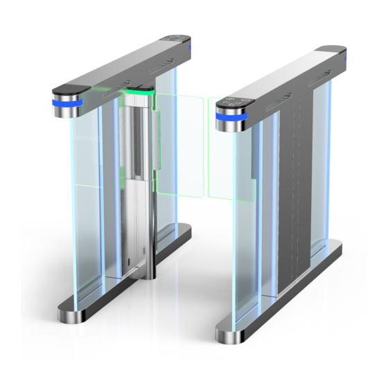
- Page 1 Speed Gate Turnstile User Manual Please read and follow the installation instructions before operating the equipment, and save the instructions for future reference or for future users. www.TURNSTILES.us | patrick.mcallister@TURNSTILES.us | 303-670-1099...
-
Page 2: Table Of Contents
4.2 Operating principle of the system………………………… 5. Equipment installation……………………………… 5.1. Equipment installation instructions……………………… 6. Device function debugging………………………… 6.1 Key description…………………………………………… 6.2 Function parameter setting……………………………… 6.3 Main board wiring instructions…………………………… 7. Common fault handling…………………………… 8. Customer service…………………………………… www.TURNSTILES.us | patrick.mcallister@TURNSTILES.us | 303-670-1099... -
Page 3: Brief Introduction
6) Unified standard external electrical interface, which can be connected with a variety of card readers, and can achieve remote control and management through management computer. www.TURNSTILES.us | patrick.mcallister@TURNSTILES.us | 303-670-1099... -
Page 4: Main Specifications
Card reader (self-provided): after reading the information on the card and judging and processing, send the application pass signal (switch signal) to the main control board. Master control board: the control center of the system, which receives signals www.TURNSTILES.us | patrick.mcallister@TURNSTILES.us | 303-670-1099... - Page 5 Direction indicator light: displays the current status of the channel and guides pedestrians to pass through the channel in a safe and orderly manner. Alarm: when the system detects pedestrians entering the passage illegally, it will send out an alarm. www.TURNSTILES.us | patrick.mcallister@TURNSTILES.us | 303-670-1099...
- Page 6 Direction indicator and guide pedestrians through the gate When the system detects a pedestrian illegally entering Alarm (speaker) the passageway, it gives an alarm. Drive the mechanism Motor power supply Switch Control panel power supply www.TURNSTILES.us | patrick.mcallister@TURNSTILES.us | 303-670-1099...
-
Page 7: Operating Principle Of The System
Reread valid chi-square allowed pass. 5. Equipment Installation Attention: During installation and construction, relevant circuits should be disconnected to ensure that all circuits are correct before energizing. 5.1. Equipment installation instructions www.TURNSTILES.us | patrick.mcallister@TURNSTILES.us | 303-670-1099... - Page 8 2. After finishing the foundation surface of the installation equipment, arrange the equipment well. 3. After the hole location is determined, drill the hole and embed the anchor bolt or expansion bolt of M12. www.TURNSTILES.us | patrick.mcallister@TURNSTILES.us | 303-670-1099...
-
Page 9: Key Description
Press "ok" again to enter the H-series, press up or down to make adjustment, press "menu key" to return and save, and press "ok" to exit the setting option. Long press "menu key" for 3 seconds -- enter l-1 and press "down key" plus value d-2... www.TURNSTILES.us | patrick.mcallister@TURNSTILES.us | 303-670-1099... -
Page 10: Function Parameter Setting
For example: 0: Welcome, 1: Welcome back < L-5 > Right pass voice speaker Default: 15: Safe Travel Voice speaker number code from 0 to 18 For example: 0: welcome, 1: Welcome back < L-6 > infrared stack time (second) www.TURNSTILES.us | patrick.mcallister@TURNSTILES.us | 303-670-1099... - Page 11 Set the speaker volume, (value: 0-15), 0 is min volume, 15 is max volume. Default: 15 < L-13 > voice message test After entering the voice test, the gate will automatically broadcast all the voices to www.TURNSTILES.us | patrick.mcallister@TURNSTILES.us | 303-670-1099...
- Page 12 When the gate open not in desired position, you can adjust the channel position by enter the parameter setting according to the voice prompt to manually move the pendulum door toward the left direction to the desired position, press ok to save < D-3 > right open position setting www.TURNSTILES.us | patrick.mcallister@TURNSTILES.us | 303-670-1099...
- Page 13 < D-9 > Reset time Setting the time interval between swiping card 《value 0.1- 10》default:0.1 < D-10 > Buffer strength from gate closing (master) The buffer strength is adjusted, the larger the value, the faster the closing speed www.TURNSTILES.us | patrick.mcallister@TURNSTILES.us | 303-670-1099...
- Page 14 The sensitivity setting when the gate hit pedestrian or in the face of obstacle, the smaller the value is , the higher sensitivity . Note: this setting only be effective when Resistance rebound Mode is set. Value: 1-99, default is 75. < D-18 > Physical clamping current time www.TURNSTILES.us | patrick.mcallister@TURNSTILES.us | 303-670-1099...
- Page 15 When the swinging door is in the closed non-working state, the reverse force can be adjusted when the swinging door is forced open by the external force. The larger the value, the greater the force ( value 1-20), default:14 www.TURNSTILES.us | patrick.mcallister@TURNSTILES.us | 303-670-1099...
-
Page 16: Main Board Wiring Instructions
Motor phase green(thick) blue(thick) black(thin) yellow(thin) Motor Hall green(thin) blue(thin) red(thin) Motor wiring (white, blue and green) Motor Name Color PCB screen print white(thick) Motor phase blue(thick) green(thick) black(thin) white(thin) Motor hall blue(thin) green(thin) red(thin) www.TURNSTILES.us | patrick.mcallister@TURNSTILES.us | 303-670-1099... - Page 17 Speed Gate Turnstile User Manual www.TURNSTILES.us | patrick.mcallister@TURNSTILES.us | 303-670-1099...
-
Page 18: Common Fault Handling
| patrick.mcallister@TURNSTILES.us | 303-670-1099... - Page 19 If above all are normal, it needs to replace the drive. 7.7. When E-1 or E-2 appears in digital tube of main board SetL-15,L-16 value to 1 www.TURNSTILES.us | patrick.mcallister@TURNSTILES.us | 303-670-1099...
-
Page 20: Customer Service
Warranty Card (Warranty: 3 years) Order Date: Product Name: Product Model: Customer Country: Email: Company Name: Fault descriptions with photo/video: www.TURNSTILES.us | patrick.mcallister@TURNSTILES.us | 303-670-1099...


Need help?
Do you have a question about the DS7200 and is the answer not in the manual?
Questions and answers