Table of Contents
Advertisement
Quick Links
Advertisement
Table of Contents

Subscribe to Our Youtube Channel
Related Manuals for Turnstiles TPW-321ASP


Summary of Contents for Turnstiles TPW-321ASP
- Page 1 OPERATING MANUAL AUTOMATIC SWING GATE TPW-321ASP...
-
Page 2: Table Of Contents
CONTENTS 1. INTRODUCTION ........................... 1 2. SAFETY PRECAUTIONS ........................1 3. PRODUCT DESCRIPTION ........................2 3.1 T ..........................2 ECHNICAL ETAILS 3.2 M ...................... 2 ECHNICAL PECIFICATIONS 3.3 E ...................... 3 QUIPMENT UTLINE IMENSIONS 4. BASIC OPERATION PRINCIPLE ....................... 3 4.1 B ....................... -
Page 3: Introduction
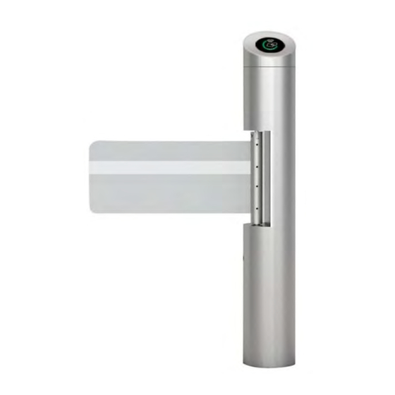
1. Introduction The Automatic Swing Gate was developed to be precise, reliable and aesthetically pleasing. Its rounded lines house a sturdy blocking mechanism designed for very low maintenance. The equipment is provided with a standard electric interface and is easily integrated into a system with write/read facilities such as magnetic card, bar code card, ID card and IC card. -
Page 4: Product Description
may be resulted. The equipment is not equipped with explosion-proof design, and it is not allowed to apply the equipment to an environment with danger of inflammable or explosion. However, it is optional for the user to purchase products of other type for the purpose. 3. -
Page 5: Equipment Outline Dimensions
5) Passing speed: 20-40 person/min 6) Main-board voltage: 24VDC 7) Max current: 5A 8) Working Environment: Indoor/Outdoor 9) Input port: dry contact signal; 10) Communications port: RS232/RS485 electric standard, communications range: ≤1200m. 3.3 Equipment Outline Dimensions Automatic Swing Gate is with a complete set of types and specifications and can be divided into types as given below. -
Page 6: Equipment Operation Mode
time. The standard default is 5 seconds. As to the read/write system such as magnetic card, bar code card and ID card are the same as that given above, except that the determination of legal card and the barrier open signal of turnstile main control board are carried out by the administrative computer. - Page 7 2) After making sure of the system constitution and working principles, please make an overall plan to be ready for the installation. 3) Please arrange the equipment in order after neatening the ground surface. 4) After fixing the positions of the holes, drill and pre-embed the ground bolt or the expansion bolt of M12.
-
Page 8: Equipment Functional Test
11) Screw the nuts after all equipment has been tested to work well. Notice: 1. The depth of the PVC tubes buried shall be more than 60mm. The height above the ground shall be more than 50mm. And the exit of the PVC tube shall be bent return so as to avoid the water falls in. -
Page 9: Operation Instruction Of The Equipment
The turnstile should carry out the relative actions reliably when the upstream management software is used to carry out operations for the turnstile such as rod up/down, open barrier, counting value of read/reset counter. If not, it is necessary to check carefully the communications lines and connectors. -
Page 10: Regular Maintenance
7. Regular Maintenance 1) The housing of the equipment is of a sub-polish stainless steel. It is required to clean regularly with soft cloth so as to keep a clean and polish surface. It is forbidden to clean the surface with a hard object; otherwise, the appearance may be affected. It is also forbidden to wash it with water, otherwise, short circuit may occur in the electric control system and the equipment may be damaged. - Page 11 Attached Figure 1 After login, it will show the main window, as follows: Attached Figure 2 System setting Control information 1) Working mode setting (for optical turnstile): NO mode: normal open, gate stay in open state, if passenger sign-in/sign0out successfully;...
- Page 12 Entry/exit forbidden: entry/exit way barring. Entry/exit free: gate in free mode, let passenger pass through freely without sign-in/sign-out. 3) Door closing time: setting the max time for each passenger entering the passage. The value effective range is 1-60, unit is second. Default: 5 4) Entry counter reset: clear entry counting value.
- Page 13 Attached Figure 4...
- Page 14 2) The instructions of turnstile control panel Turnstile control panel instructions shown as Attached Figure 4 . Attached Figure 4...
- Page 15 3) The wiring instructions for the external interface of control panel The common wirings for customer: OPEN_R: Entrance open signal access (dry contact signal) 1、 OPEN_L: Exit open signal access (dry contact signal) 2、 EMO: Emergency signal access (dry contact signal) 3、...
-
Page 16: Appendix C Cmolo Turnstile Control Board
] or overtime (waiting 0x02 0xFF 0x00 0x04 time is 2 seconds). The control board of turnstiles will send related parameters after received feedback signal. Every parameter sent by main board needs the feedback signal [address(if you choose UDP interface, no need address)+ 0x02 0xFF 0x00 0x04 from PC, then send the next parameter. - Page 17 1.2 Setting control board parameters via PC After PC connects with control board successfully, corresponding commands can be sent to the control board to set the parameters. The control board will send success return signal (0x02 0x44 0x00 0x04) to PC if the setting is successful, or the control board will send failure return signal (0x02 0xF4 0x00 0x04).
-
Page 18: Control Board Sending Command
6) Entry & Exit Counter Switch 7) IR Sensors’ Sensitivity (inapplicable to tripod turnstiles) 8) Auto-Drop & Raise (only applicable to fully automatic tripod turnstiles) For detailed command formats, please refer to 3. Control Board Receiving Command. Below is the flow Chart: 2. - Page 19 ASCII code of the door opening & closing speed 0x42 0x01 0x31-0x37 ranking (1-7) (inapplicable to tripod turnstiles) ASCII code of the IR sensors’ sensitivity ranking 0x81 0x01 0x31-0x35 (1-5) (inapplicable to tripod turnstiles)
-
Page 20: Control Board Receiving Command
3. Control Board Receiving Command Control Board receiving Command Format Command Command Command Command Start Command Content Command Descriptions Type Length Symbol Symbol Connecting control 0xFF 0x00 NULL board request Reading command 0x44 0x00 NULL success return signal Setting equipment working mode: 0x30:NO Mode;... - Page 21 0x30:entry counter reset; 0x31:exit counter reset; Setting tripod turnstile auto-drop & raise (only applicable to fully automatic 0x24 0x01 0x30-0x31 tripod turnstiles ): 0x30:auto-drop; 0x31:auto-raise Reading entry & exit counting: 0x30: reading entry counting; 0x31: reading exit counting; 0x28 0x01 0x30-0x31...
- Page 22 0x32: pass by upper left arrow 0x33: pass by bottom left arrow 0x34: pass by upper right arrow 0x35: pass by bottom right arrow Set the default display image of LED panel on both sides. After receiving this command, the control panel will set the display image of LED panel on both sides according to the command...
Need help?
Do you have a question about the TPW-321ASP and is the answer not in the manual?
Questions and answers