Table of Contents
Advertisement
CAUTION, MICROWAVE RADIATION................................................................................................ 2
WARNING/GENERAL IMPORTANT INFORMATION.........................................................................
SERVICING.........................................................................................................................................
PRODUCT SPECIFICATIONS............................................................................................................
APPEARANCE VIEW..........................................................................................................................
OPERATION SEQUENCE..................................................................................................................
FUNCTION OF IMPORTANT COMPONENTS................................................................................... 11
TROUBLESHOOTING GUIDE............................................................................................................ 13
TEST PROCEDURES......................................................................................................................... 15
TOUCH CONTROL PANEL.................................................................................................................. 22
SERVICING......................................................................................................................................... 27
COMPONENT REPLACEMENT AND ADJUSTMENT PROCEDURE............................................... 28
MICROWAVE MEASUREMENT......................................................................................................... 33
TEST DATA AT A GLANCE................................................................................................................ 34
SCHEMATIC DIAGRAMS................................................................................................................... 35
PICTORIAL DIAGRAM........................................................................................................................ 39
POWER UNIT CIRCUIT DIAGRAM.................................................................................................... 40
C. P. U. UNIT CIRCUIT DIAGRAM..................................................................................................... 41
PRINTED WIRING BOARD OF POWER UNIT DIAGRAM................................................................. 42
PARTS LIST........................................................................................................................................ 43
EXPLODED DIAGRAM OF OVEN PARTS......................................................................................... 46
CONTROL PANEL/DOOR PARTS..................................................................................................... 47
MISCELLANEOUS/PACKING & ACCESSORIES.............................................................................. 48
SERVICE MANUAL
In interests of user-safety the oven should be restored to its original
condition and only parts identical to those specified should be
used.
TABLE OF CONTENTS
SHARP CORPORATION
R-84ST -
MICROWAVE OVEN WITH
GRILL AND CONVECTION
R-84ST
MODEL
1
S40193R84SEHW
Page
3
4
7
8
9
Advertisement
Table of Contents

Subscribe to Our Youtube Channel
Related Manuals for Sharp R-84ST


Summary of Contents for Sharp R-84ST
-
Page 1: Table Of Contents
POWER UNIT CIRCUIT DIAGRAM....................40 C. P. U. UNIT CIRCUIT DIAGRAM..................... 41 PRINTED WIRING BOARD OF POWER UNIT DIAGRAM..............42 PARTS LIST............................43 EXPLODED DIAGRAM OF OVEN PARTS..................46 CONTROL PANEL/DOOR PARTS..................... 47 MISCELLANEOUS/PACKING & ACCESSORIES................48 SHARP CORPORATION R-84ST -... -
Page 2: Caution Microwave Radiation
Alle mikrobølgeindgange og-udgange, bølgeledere, flanger og tætningsstrimler må være forsvarligt udført. Anvend aldrig ovnen uden en mikrobølgesabsorberende anordning. Se aldrig ind i en åben bølgeleder eller antenne, mens ovnen er i brug. R-84ST -... -
Page 3: Warning/General Important Information
GRILL AND CONVECTION MICROWAVE OVEN R84ST GENERAL IMPORTANT INFORMATION This Manual has been prepared to provide Sharp Corp. Service engineers with Operation and Service Information. It is recommended that service engineers carefully study the entire text of this manual, so they will be qualified to render satisfactory customer service. -
Page 4: Servicing
Sharp beveelt ten sterkste aan dat, voor zover mogelijk, onderdelen. defecten worden opgespoord wanneer de stekker uit het stopcontact is gehaald. - Page 5 är varmt. Om vattnet fortfarande är kallt utför Du 3 steg kontroller och kontrollerar anslutningarna till varje Sharp rekommenderar att felsökning sker med strömmen enskild komponent på nytt. fränkopplad. Ibland kan det var nödvändigt att koppla på...
- Page 6 è rimasta fredda, eseguire i tre controlli iniziali e verificare nuovamente i collegamenti del componente in Sharp raccomanda, nei limiti del possibile, che la ricerca questione. dei guasti avvenga in assenza di alimentazione elettrica. In alcuni casi tuttavia, può essere necessario alimentare Dopo aver portato a termine le operazioni di manutenzione l'apparecchio dopo aver rimosso la scatola esterna.
-
Page 7: Product Specifications
CLOCK SETTING key CLOCK SETTING key FRENCH FRIED POTATOE key FROZEN PIZZA/FROZEN QUICHE key Net Weight Approx. 20 kg As part of our policy of continuous improvement, we reserve the right to alter design and specifications without notice R-84ST -... -
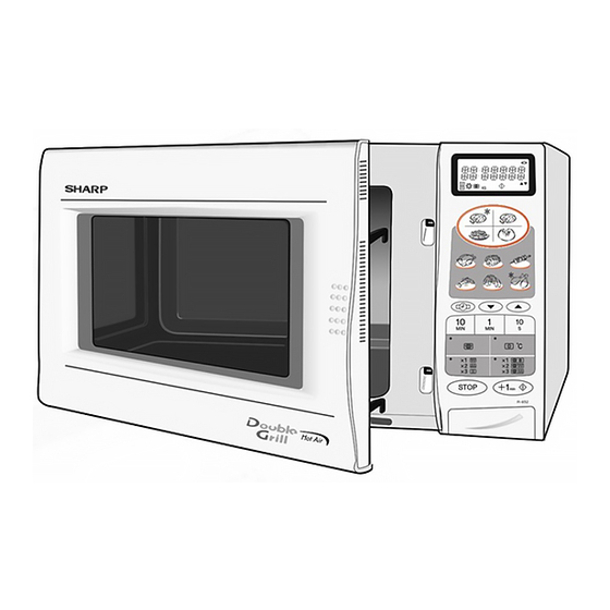
Page 8: Appearance View
2 PRESSES = BOTTOM GRILL 3 PRESSES = TOP & BOTTOM GRILL 20 MICROWAVE POWER LEVEL key Press to change the microwave power setting 21 CLOCK SETTING key 22 FRENCH FRIED POTATO key 23 FROZEN PIZZA/FROZEN QUICHE key R-84ST -... -
Page 9: Operation Sequence
The oven been interrupted, because the relay RY1 stay closed. will shut-down completely after 30 minutes. R-84ST -... - Page 10 1. The numbers on the digital readout start the count down to generated by the magnetron. zero. 5. Now, the food is cooked by microwave and bottom grill 2. The oven lamp, cooling fan motor and turntable motor are simultaneously. energized. R-84ST -...
-
Page 11: Function Of Important Components
And the contacts (COM-NC) must be closed. STOP SWITCH SW2 1. When the oven door is closed, the contacts (COM-NO) of the switch must be closed. 2. When the oven door is opened, the contacts (COM-NO) of switch must be opened. R-84ST -... - Page 12 T will cut off and operation of is located at the base of the oven cavity. the magnetron MG will be stopped. The defective thermal cut-out must be replaced with a new one. R-84ST -...
-
Page 13: Troubleshooting Guide
“Test Procedure” section. IMPORTANT: If the oven becomes inoperative because of a blown fuse F2 (F8A) in the monitored latch switch - monitor switch circuit, check the monitored latch switch and monitor switch before replacing the fuse F2 (F8A). R-84ST -... - Page 14 CONVECTION FAN MOTOR FAN MOTOR TURNTABLE MOTOR THERMAL CUT-OUT 150˚C TC2 THERMAL CUT-OUT 125˚C TC1 THERMISTOR MONITOR SWITCH SW3 STOP SWITCH SW2 MONITORED LATCH SWITCH SW1 HIGH VOLTAGE CAPACITOR H.V. HARNESS H.V. RECTIFIER ASSEMBLY HIGH VOLTAGE TRANSFORMER MAGNETRON R-84ST -...
-
Page 15: Test Procedures
3. Place the load on the centre of the shelf. 4. Operate the microwave oven at HIGH for the temperature of the water rises by a value ∆ T of (10 ± 2) K. 5. Stir the water to equalize temperature throughout the vessel. R-84ST -... - Page 16 Reverse the meter leads and note this second reading. The normal resistance is infinite in one direction and more than 100 kΩ in the other direction. CARRY OUT 4R CHECKS ASYMMETRIC ASYMMETRIC RECTIFIER TEST RECTIFIER CARRY OUT 3D CHECKS. HIGH VOLTAGE RECTIFIER R-84ST -...
- Page 17 Connect the ohmmeter leads to Pin No's C1 and C3 of the thermistor harness. Room Temperature Resistance 20˚C - 30˚C Approximately 359.9 kΩ - 152 kΩ If the meter does not indiicate above resistance, replace the thermistor. CARRY OUT 4R CHECKS. R-84ST -...
- Page 18 INDICATION OF OHMMETER Between N and L Approx. 680 kΩ Between terminal N and WHITE Short circuit Between terminal L and RED Short circuit If incorrect readings are absorbed, replace the noise filter unit. CARRY OUT 4R CHECKS R-84ST -...
- Page 19 10M&ohm in the cold start. If the results of above test 1 and/or 2 are out of above specifications, the heating element is probably faulty and should be replaced. CARRY OUT 4R CHECKS R-84ST -...
- Page 20 If the control unit does not respond, it is faulty and must be replaced. If a specific pad does not respond, the above method may be used (after clearing the control unit) to determine if the control unit or key pad is at fault. CARRY OUT 4R CHECKS. R-84ST -...
- Page 21 (check primary coil resistance). If any abnormal condition is detected, replace the defective parts. VRS1 POWER CARRY OUT 4R CHECKS. R-84ST -...
-
Page 22: Touch Control Panel
The power source synchronizing signal is available in order to compose a basic standard time in the clock circuit. It accompanies a very small error because it works on commercial frequency. 4) ACL A circuit to generate a signal which resets the LSI to the R-84ST -... - Page 23 When any one of G9 line keys on key matrix is touched, a corresponding signal will be input into P44. INT1 Terminal not used. INT0 Signal to synchronized LSI with commercial power source frequency(50Hz). This is basic timing for time processing of LSI. H : GND L (-5V) 20 msec. R-84ST -...
- Page 24 22 sec. 26 sec. on and off within a 48 second time 30 % 16 sec. 32 sec. base in accordance with the 20 % 12 sec. 36 sec. 10 % 8 sec. 40 sec. special program in LSI. R-84ST -...
- Page 25 SEG17 (73) ....SEG23 (23) SEG37 (53) ....SEG 3 ( 3) SEG18 (72) ....SEG22 (22) SEG38 (52) ....SEG 2 ( 2) SEG19 (71) ....SEG21 (21) SEG39 (51) ....SEG 1 ( 1) SEG20 (70) ....SEG20 (20) R-84ST -...
- Page 26 Common data signal: COM2. Connected to LCD (Pin No. 34). COM1 Common data signal: COM1. Connected to LCD (Pin No. 33). COM4 Terminal not used. 98-99 VL3-VL2 Power source voltage input terminal. Standard voltage for LCD. Terminal not used. R-84ST -...
-
Page 27: Servicing
After checking the performance of the touch control panel, 1) Disconnect the power supply cord. 2) Open the door and block it open. 3) Re-connect the leads to the primary of the power transformer. 4) Re-install the outer case (cabinet). R-84ST -... -
Page 28: Component Replacement And Adjustment Procedure
4. Disconnect the main wire harness from the high voltage transformer. CONTROL PANEL REMOVAL 1. CARRY OUT 3D CHECKS 4. Lift up the control panel assembly and pull it forward. Now 2. Remove outer wrap. the control panel assembly is free. 3. Disconnect wiring panel. R-84ST -... - Page 29 11. Now, the fan motor is free. Coil Groove joint pliers Shaft Shaft These are the position where should be Axis pinched with pliers Stator Stator Center of Rotor Table bracket Bracket Rotor Side view Rear view R-84ST -...
- Page 30 6. Now, the convection fan duct assembly is free. 11. Remove the ring on the convection motor shaft. 7. Remove the one (1) nut holding the convection fan, 12. Now, the convection motor is free. R-84ST -...
- Page 31 1. In and out play of door remains less than 0.5 mm when latched position. First check latch hook position, pushing DOOR OPEN BUTTON and pulling the door toward the oven face. The results Figure C-6. Switch Adjustment R-84ST -...
- Page 32 4. Re-install door panel to door frame by fitting six (6) tabs of door frame to six (6) holes of door panel. 5. Hold the door panel to the door frame with four (4) screws. 6. Locate door panel hinge pins into cavity hinge location holes. R-84ST -...
-
Page 33: Microwave Measurement
6. The microwave radiation emission should be measured instrumentations as prescribed by the performance at any point of 5cm or more from the external surface of the oven. mW cm mW cm Microwave leakage measurement at 5 cm distance R-84ST -... -
Page 34: Test Data At A Glance
240 - 250 V 25W E14 High voltage capacitor 1.13µF AC 2100V Magnetron Filament < 1Ω Filament - chassis ∞ ohm. High voltage transformer Filament winding < 1Ω. Secondary winding Approx. 99Ω. Primary winding Approx. 2.4Ω WARNING: DISCONNECT THE PLUG WHEN MEASURING RESISTANCE. R-84ST -... -
Page 35: Schematic Diagrams
2. " . O" APPEARS ON DISPLAY. NOISE F2: FUSE F8A FILTER TC1: THERMAL CUT-OUT TC2: OVEN THERMAL SW2: THERMISTOR CUT-OUT STOP SWITCH SW3: MONITOR ASYMMETRIC SW1: MONITORED LATCH SWITCH SWITCH RECTIFIER Figure O-1(c) Oven Schematic-OFF Condition after the oven door is closed. R-84ST -... - Page 36 4. START KEY TOUCHED. F2: FUSE F8A NOISE FILTER TC1: THERMAL CUT-OUT TC2: OVEN THERMAL SW2: THERMISTOR CUT-OUT STOP SWITCH SW3: MONITOR SW1: MONITORED LATCH SWITCH ASYMMETRIC SWITCH RECTIFIER Figure O-3(b) Oven Schematic-Grill cooking Condition (BOTTOM GRILL mode) R-84ST -...
- Page 37 6. START KEY TOUCHED. NOISE F2: FUSE F8A FILTER TC1: THERMAL CUT-OUT TC2: OVEN THERMAL SW2: THERMISTOR CUT-OUT STOP SWITCH SW3: MONITOR ASYMMETRIC SW1: MONITORED LATCH SWITCH SWITCH RECTIFIER Figure O-5(a) Oven Schematic-Dual cooking Condition (Microwave and Convection mode) R-84ST -...
- Page 38 5. START KEY TOUCHED. NOISE F2: FUSE F8A FILTER TC1: THERMAL CUT-OUT TC2: OVEN THERMAL SW2: THERMISTOR CUT-OUT STOP SWITCH SW3: SW1: MONITORED LATCH SWITCH MONITOR ASYMMETRIC SWITCH RECTIFIER Figure O-5(c) Oven Schematic-Dual cooking Condition (Microwave and Buttom Grill mode) R-84ST -...
-
Page 39: Pictorial Diagram
PICTORIAL DIAGRAM R-84ST -... -
Page 40: Power Unit Circuit Diagram
WH1-2 STOP SWITCH WH1-1 STOP SWITCH NOTE 1. NOTE 2. : IF NOT SPECIFIED, 1/4W ± 5% WH1-n 15P WIRE HARNESS : IF NOT SPECIFIED, 0.1µF / 50V : IF NOT SPECIFIED, 1SS270A Figure S-2. Power Unit Circuit R-84ST -... -
Page 41: Unit Circuit Diagram
CPU UNIT CIRCUIT DIAGRAM R-84ST -... -
Page 42: Printed Wiring Board Of Power Unit Diagram
PRINTED WIRING BOARD OF POWER UNIT DIAGRAM VRS1 POWER CONT Figure S-4. Printed Wiring Board of Power Unit R-84ST -... -
Page 43: Parts List
LED sheet 3- 10 XEPSD30P10XS0 Screw : 3mm x 10mm HOW TO ORDER REPLACEMENT PARTS To have your order filled promptly and correctly, please furnish the following information. 1. MODEL NUMBER 2. REF. NO. 3. PART NO. 4.DESCRIPTION R-84ST -... - Page 44 Air deflect cushion 4-32 LANGQA004URP0 U Convection air angle 4-33 PDUC-A003URP0 U Convection duct 4-34 PFPF-A001URE0 U Heat intercept 4-35 PCOVQA001URP0 U Rear heat cover 4-36 PPIP-A001UR10 U Pipe 4-37 PCUSUA018URE0 U Back plate cushion 4-38 NFANMA001URP0 U Convection fan R-84ST -...
- Page 45 Screw: 3mm x 6mm 7-18 XFPSD40P08000 Screw: 4mm x 8mm 7-19 XFPSD50P10KS0 Screw: 5mm x 10mm 7-20 LX-CZA001URE0 Screw: 4mm x 12mm 7-21 XBPWW30P05K00 Screw: 3mm x 5mm 7-22 XWHUW50-08000 Washer: 5mm x 0.8mm 7-23 XOTSD40P12000 Screw: 4mm x 12mm R-84ST -...
-
Page 46: Exploded Diagram Of Oven Parts
4-23 4-17 7-10 4-10 4-13 7-20 4-12 7-18 4-15 4-19 7-19 4-25 4-31 4-24 7-20 4-20 4-29 7-20 NOTE: In the event of removing the turntable motor cover this part should be refitted using screw connection: LX-EZA045WRE0 (7-16) R-84ST -... -
Page 47: Control Panel/Door Parts
CONTROL PANEL PARTS AND DOOR PARTS CONTROL PANEL PARTS 3 - 2 3-10 3 - 4 3 - 8 3 - 9 3-10 3 - 1 3 - 7 3 - 3 3 - 6 3 - 5 DOOR PARTS R-84ST -... -
Page 48: Miscellaneous/Packing & Accessories
MISCELLANEOUS / PACKING & ACCESSORIES MISCELLANEOUS Actual wire harness may be different than illustration. COPYRIGHT C 2001 BY SHARP CORPORATION ALL RIGHT RESERVED. No part of this publication may be reproduced, stored in a retrieval system, or transmitted in any form or by any means, electronic, mechanical, photocopying, recording, or otherwise, without prior written permission of the publisher.
Need help?
Do you have a question about the R-84ST and is the answer not in the manual?
Questions and answers