Table of Contents
Advertisement
Quick Links
SERVICING ............................................................................................................................................. 2
CAUTION, MICROWAVE RADIATION .................................................................................................... 3
WARNING ................................................................................................................................................. 3
APPEARANCE ......................................................................................................................................... 4
PRODUCT SPECIFICATIONS ................................................................................................................. 5
OPERATION SEQUENCE ........................................................................................................................ 6
TEST PROCEDURES ............................................................................................................................. 7
TOUCH CONTROL PANEL ASSEMBLY .............................................................................................. 10
COMPONENT REPLACEMENT AND ADJUSTMENT PROCEDURE .................................................. 16
MICROWAVE MEASUREMENT ........................................................................................................... 18
SCHEMATIC DIAGRAM ........................................................................................................................ 19
PICTORIAL DIAGRAM .......................................................................................................................... 20
POWER UNIT CIRCUIT DIAGRAM ........................................................................................................ 21
CPU UNIT CIRCUIT DIAGRAM .............................................................................................................. 22
PRINTED WIRING BOARD DIAGRAM .................................................................................................. 23
PARTS LIST .......................................................................................................................................... 24
EXPLODED DIAGRAM OF OVEN PARTS ............................................................................................ 27
CONTROL PANEL/DOOR PARTS ......................................................................................................... 28
MISCELLANEOUS/PACKING & ACCESSORIES .................................................................................. 29
SERVICE MANUAL
MODEL
In interests of user-safety the oven should be restored to its original
condition and only parts identical to those specified should be used.
TABLE OF CONTENTS
SHARP CORPORATION
R-84STM - 1
GRILL AND CONVECTION
MICROWAVE OVEN
R-84STM
S71101R84STM/
Page
Advertisement
Table of Contents

Subscribe to Our Youtube Channel
Related Manuals for Sharp R-84STM


Summary of Contents for Sharp R-84STM
-
Page 1: Table Of Contents
POWER UNIT CIRCUIT DIAGRAM ......................21 CPU UNIT CIRCUIT DIAGRAM ......................22 PRINTED WIRING BOARD DIAGRAM ....................23 PARTS LIST ............................24 EXPLODED DIAGRAM OF OVEN PARTS .................... 27 CONTROL PANEL/DOOR PARTS ......................28 MISCELLANEOUS/PACKING & ACCESSORIES .................. 29 SHARP CORPORATION R-84STM - 1... -
Page 2: Servicing
Sharp recommend that wherever possible, fault-finding is carried out with the supply disconnected. In some cases, it may be necessary to connect the supply with the cover removed to carry out fault investigation in the control circuitry. -
Page 3: Caution Microwave Radiation
IMPORTANT THE WIRES IN THIS MAINS LEAD ARE COLOURED IN ACCORDANCE WITH THE FOLLOWING CODE: GREEN-AND-YELLOW : EARTH BLUE : NEUTRAL BROWN : LIVE If the mains lead is replaced, only part number QACCBA004URE3 should be used R-84STM - 3... -
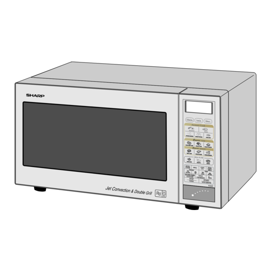
Page 4: Appearance
EXPRESS DEFROST keys MEAL IN ONE keys CONV. ( C) key DUAL CONV./GRILL key LESS/MORE keys INFO key START/AUTO MINUTE key STOP/CLEAR key KITCHEN TIMER/CLOCK SET key WEIGHT CONVERSION key WEIGHT keys MICRO. POWER key GRILL key R-84STM - 4... -
Page 5: Product Specifications
This is due to the grill elements turning on and off in order to regulate the oven temperature. This will not affect the cooking results as long as the operation manual and cook book are followed correctly. R-84STM - 5... -
Page 6: Operation Sequence
SW1. 3-1. When the oven door is opened during or after the cycle of a cooking program, the monitored latch switch SW1 and stop switch SW3 must open their contacts (COM- R-84STM - 6... -
Page 7: Test Procedures
The power output of this oven is rated using the method specified by IEC-60705. Full details of how to carry out this procedure can be found in the Sharp Technical Training notes which is available from Sharp Parts Centre (part number SERV-LITMW01). - Page 8 CHICKEN QUARTERS (INSTANT COOK) BREAKFAST START MICRO. MORE POWER LESS AUTO MINUTE DOWN OVEN CHIPS STOP DUAL CONV. / KG / LB KITCHEN TIMER CONV. GRILL CONVERSION ( ˚C ) CLOCK SET CLEAR PASTA DISH CARRY OUT 4R CHECKS. R-84STM - 8...
- Page 9 (check primary coil resistance). If any abnormal condition is detected, replace the defective parts. VRS1 POWER CARRY OUT 4R CHECKS. R-84STM - 9...
-
Page 10: Touch Control Panel Assembly
It accompanies a very small error because it works on commercial frequency. 4) ACL A circuit to generate a signal which resets the LSI to the R-84STM - 10... - Page 11 This is basic timing for time processing of LSI. L (-5V) 20 msec. Key strobe signal. Signal applied to touch-key section. A pulse signal is input to P44 - P47 terminal while one of G8 line key on matrix is touched. R-84STM - 11...
- Page 12 48 second time 40 % 22 sec. 26 sec. base in accordance with the 30 % 16 sec. 32 sec. special program in LSI. 20 % 12 sec. 36 sec. 10 % 8 sec. 40 sec. R-84STM - 12...
- Page 13 SEG17 (73) ....SEG23 (23) SEG37 (53) ....SEG 3 ( 3) SEG18 (72) ....SEG22 (22) SEG38 (52) ....SEG 2 ( 2) SEG19 (71) ....SEG21 (21) SEG39 (51) ....SEG 1 ( 1) SEG20 (70) ....SEG20 (20) R-84STM - 13...
- Page 14 Common data signal: COM2. Connected to LCD (Pin No. 34). COM1 Common data signal: COM1. Connected to LCD (Pin No. 33). COM0 Terminal not used. 98-99 VL3-VL2 Power source voltage input terminal. Standard voltage for LCD. Terminal not used. R-84STM - 14...
- Page 15 5) Be sure to use specified components where high panel, precision is required. 1) Disconnect the power supply cord. 2) Open the door and block it open. 3) Re-connect the leads to the primary of the power R-84STM - 15...
-
Page 16: Component Replacement And Adjustment Procedure
1. In and out play of door remains less than 0.5 mm when DOOR OPEN BUTTON latched position. First check latch hook position, pushing and pulling upper portion of door toward the oven face. Figure C-6. Switch Adjustment R-84STM - 16... - Page 17 Re-install latch head to microwave leakage. door frame. 4. Re-install door panel to door frame by fitting six (6) tabs of door frame to six (6) holes of door panel. R-84STM - 17...
-
Page 18: Microwave Measurement
Dotted line indicaes path taken by the leakage detector Whilst the maximum leakage permitted in BS EN 60335-2-25 is 50 W/m (equivalent to 5mW/cm ), it is not normal to detect anything signifcant, and therefore any detected leakage should be investigated. R-84STM - 18...
Need help?
Do you have a question about the R-84STM and is the answer not in the manual?
Questions and answers