
Related Manuals for Sony PDW-F355L


Summary of Contents for Sony PDW-F355L
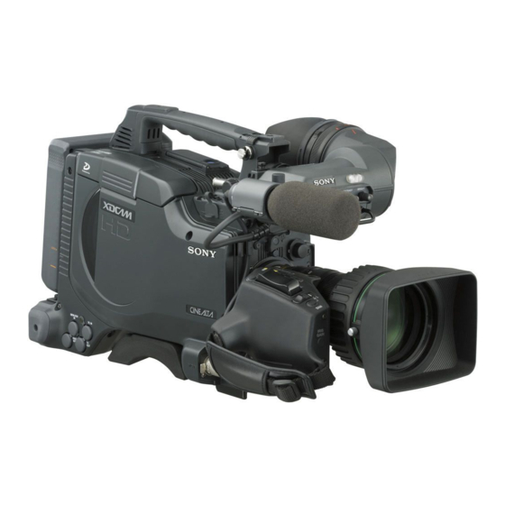
- Page 1 3-270-573-11 (1) Professional Disc Camcorder Operating Instructions Before operating the unit, please read this manual thoroughly and retain it for future reference. PDW-F355L © 2007 Sony Corporation...
- Page 2 Owner’s Record The model and serial numbers are located on the top. Record these numbers in the spaces provided below. Refer to them whenever you call upon your Sony dealer regarding this product. Model No. Serial No. WARNING To reduce the risk of fire or electric shock, do not expose this apparatus to rain or moisture.
- Page 3 E1 (residential), E2 (commercial and light industrial), E3 (urban outdoors) and E4 (controlled EMC environment, ex. TV studio). The manufacturer of this product is Sony Corporation, 1-7-1 Konan, Minato-ku, Tokyo, Japan. The Authorized Representative for EMC and product safety is Sony Deutschland GmbH, Hedelfinger Strasse 61, 70327 Stuttgart, Germany.
-
Page 4: Table Of Contents
Table of Contents Foreword ... 7 Before Use ...7 Frame Frequency Indications for Interlaced Signals ...7 Chapter 1 Overview Product Configurations ... 8 Features ... 9 Camera Features ...9 Features of the Optical Disc Drive (VDR) .10 Input/Output Features ...11 Other Features...11 Location and Function of Parts ... - Page 5 Setting the Thumbnail Image at Recording Time ...66 Recording – Advanced Operations ... 67 Time-lapse Video Recording (Interval Rec Function) ...67 Slow & Quick Motion Shooting ...68 Starting a Shoot with a Few Seconds of Pre- Stored Picture Data (Picture Cache Function) ...69 Assigning User-Defined Clip Titles Automatically ...71...
- Page 6 Loading Saved Data from a “Memory Stick” ...150 Saving and Loading Scene Files ... 151 Saving a Scene File...151 Loading Scene Files...153 Resetting the Settings of the Camcorder to the Standard Settings...154 Chapter 7 File Operation Overview ... 156 Directory Structure ...156 File Operation Restrictions ...157...
-
Page 7: Foreword
Foreword Before Use After purchasing this unit, before operating, it is necessary to set the region of use and the frame frequency. (Unless these settings are made, the unit will not operate.) For details of these settings, see “Setting the Area of Use and the Frame Frequency”... -
Page 8: Chapter 1 Overview
Overview Product Configurations The PDW-F355 Professional Disc Camcorder comprises the components and accessories supplied as shown in the followoing figure. DXF-20W Viewfinder Stereo Microphone Test chart for flange focal length adjustment a) Use a tripod adaptor with a suffix of “-E” or later on the model name. -
Page 9: Features
The use of Professional Disc adds high reliability to recording and playback, and the unit also includes many playback and editing functions exploiting the possibilities of random access. 1) XDCAM and “Professional Disc” are trademarks of Sony Corporation. 2) HD: High Definition 3) SD: Standard Definition Camera Features... -
Page 10: Features Of The Optical Disc Drive (Vdr)
Features of the Optical Disc Drive (VDR) Support for HD/SD recording and playback formats For HD video recording format, MPEG-2 MP@HL compression is used, and the image quality (bit rate) and recording time can be selected according to the shooting application. -
Page 11: Input/Output Features
UHF synthesized tuner (supplied separately) without using any connecting cable. • The audio signals to be recorded on the disc can be freely selected from the audio inputs to the stereo microphone, AUDIO IN connectors and the UHF synthesized tuner, and assigned to any desired audio channel. -
Page 12: Location And Function Of Parts
Location and Function of Parts Front 1 Lens mount securing rubber 2 Lens mount cap 3 LENS connector 4 AUTO W/B BAL switch 5 REC button 6 Auto focus ranging sensor a Lens mount securing rubber After locking the lens in position using the lens locking lever, fit this rubber over the lower of the two projections. -
Page 13: Shutter Switch
iris function does not operate correctly, select an appropriate position. When this selector is used with the menu item for filter selection display set to ON (see page 138), the new setting appears on the viewfinder screen for about 3 seconds. You can change a MAINTENANCE menu setting so that different white balance settings can be stored for different FILTER selector positions. -
Page 14: Right Side
MAN. However, when using the interval recording mode, the video light is automatically turned on immediately before recording starts. • To ensure proper operation of the video light, Sony recommends the use of the BP-GL95 Battery Pack with the camcorder. -
Page 15: Lcd Monitor
16. i MENU switch When flicking toward ON, the menu is displayed. When flicking toward STATUS, the status of the camcorder (of current settings) is displayed. For details, see “Displaying Menus” on page 132. j WHITE BAL (white balance memory) switch Controls adjustment of the white balance. -
Page 16: Status Display On The Lcd Monitor
Display indication Meaning Video with When the MENU switch is flicked superimposed toward STATUS, the principal settings information of this unit appear as on the viewfinder screen. Video without The video only appears. superimposed information Status display Counter indications, warnings, audio levels, and similar information appears. -
Page 17: Video Format
a Video format Indicates the format of video being currently played back or recorded. HD HQ: HQ (high quality) mode in the MPEG HD video format HD SP: SP (standard play) mode in the MPEG HD video format HD LP: LP (long play) mode in the MPEG HD video format DVCAM: DVCAM format b Playback indicator... -
Page 18: Earphone Jack
1) E-E: Abbreviation of “Electric-to-Electric”. In E-E mode, video and audio signals input to the camcorder are output after passing through internal electric circuits only. This can be used to check input signals. For details about alarms, see “Operation Warnings” on page 167. -
Page 19: Next Button
through the earphones. Plugging earphones into the jack automatically cuts off the sound from the built-in speaker. You can select monaural or stereo on the AUDIO-2 page of the MAINTENANCE menu. f EJECT button and indicator Press this button to insert a disc or eject the disc. The indicator flashes while the disc is being ejected. -
Page 20: Shift Button
a MONITOR (audio monitor selection) switches By means of combinations of the two switches, you can select audio that you want to hear through the built-in speaker or optional earphones. Position of left- Position of right- side switch side switch CH-1/CH-3 CH-1/2 CH-2/CH-4... -
Page 21: Left Side And Upper Section
R-RUN mode. CLOCK: Records timecode synchronized to the internal clock. Regardless of the setting of the F-RUN/SET/R- RUN switch, the camcorder operates in F-RUN mode. 5 Accessory fitting shoe 6 Shoulder strap fitting 7 Viewfinder left-to-right positioning ring... -
Page 22: Shoulder Pad
c Viewfinder front-to-back positioning knob Loosen this knob to adjust the front-to-back position of the viewfinder (see page 36). d Lid of the disc compartment This opens when the EJECT button on the top panel is pressed. Press the side of the lid to close. e Accessory fitting shoe Attach an optional accessory such as a video light (see page 39). -
Page 23: Rear
“Attaching a UHF Synthesized Tuner” on page 41. Note For your safety, and to ensure proper operation of the camcorder, Sony recommends the use of the following battery packs: BP-GL95, BP-GL65, BP-L60S, and BP- L80S. d WRR connector (7-pin) Connect a CA-WR855 Camera Adaptor with attached WRR-855 UHF Synthesized Tuner. - Page 24 Connect an RM-B150/B750 Remote Control Unit, which makes it possible to control the camcorder remotely. Note Before connecting/disconnecting the Remote Control Unit to/from the camcorder, be sure to turn off the camcorder POWER switch. f DC OUT 12V (DC power output) connector (4-pin, female) Supplies power for a WRR-861/862 UHF Synthesized Tuner (optional) (maximum 0.2 A).
-
Page 25: Dxf-20W Viewfinder
REC/TALLY (recording/tally) indicators (red) Function as follows. • Begin flashing when you press the REC button on the camcorder or on the lens until recording starts, then stay on continuously during recording. • Indicate a fault (see page 167). -
Page 26: Status Display On The Viewfinder Screen
Status Display on the Viewfinder Screen The viewfinder screen displays not only the video picture but also characters and messages indicating the camcorder settings and operating status, a center marker, a safety zone marker, etc. When the menu screen is not displayed and the DISPLAY... -
Page 27: Gain Value
• 10 m or less (including the macro area): 0.1 m • 10 m to 100 m: 1 m • 100 m to 200 m: 10 m • 200 m to infinite distance: 50 m g Power source voltage/battery remaining capacity When the unit is powered from a battery pack or AC adaptor attached to the battery attachment shoe, indicates the remaining capacity of the power source voltage. - Page 28 r Iris setting/auto iris override Indicates the F value (iris setting) of the lens. Also, the auto iris override is displayed using two squares which appear in the upper and lower parts respectively. For details, see “Adjusting the Iris” on page 59. s Setting change and adjustment progress message display area For details, see “Change Confirmation/Adjustment...
-
Page 29: Chapter 2 Preparations
Attaching and Replacing the Lithium Battery This camcorder uses a lithium battery to retain stored data. When using the camcorder for the first time, be sure to attach the supplied lithium battery (CR2032). The camcorder will not operate correctly without this lithium battery. -
Page 30: Preparing A Power Supply
Using an AC Adaptor When using the AC-DN10 AC adaptor Mount an AC-DN10 on the camcorder in the same way as a battery pack, then connect to the AC power supply. The AC-DN10 can supply up to 100 W of power. -
Page 31: Setting The Area Of Use And The Frame Frequency
Setting the Area of Use and the Frame Frequency Using the Unit for the First Time The area of use and the frame frequency are not factory preset. Before using this unit, you need to set these items. (You cannot use the unit without setting these items.) MENU knob Set the POWER switch to the ON position. - Page 32 The FORMAT page appears. ?001 FORMAT SYSTEM REC FORMAT :MPEG HD 23.9P OUTPUT BIT RATE (HD) AUDIO CH (HD) ASPECT RATIO(DV): 16:9 COUNTRY : To change the area of use, press and turn the MENU knob to move the b mark to “COUNTRY”, then press the MENU knob.
-
Page 33: Setting The Date And Time Of The Internal Clock
Setting the Date and Time of the Internal Clock You can set the date and time of the internal clock. The date and time set here are reflected in timecode. (How to select an item in the menu screen: Turn the MENU knob to move the b mark to the desired item.) Display the TIME/DATE page of the OPERATION menu, and press the MENU knob. -
Page 34: Preparing The Lens
Caution If the lens is not firmly locked, it may come off while the camcorder is being used. This could cause a serious accident. Make sure the lens is firmly locked. It is recommended that the lens mount securing rubber be put on the lens locking lever as illustrated above. - Page 35 Flange focal length adjustment button Focus ring Zoom ring SERVO MANU. ZOOM switch Open the iris, position the supplied flange focal length adjustment chart approximately 3 meters away from the camera, and arrange the lighting to obtain a satisfactory video output. Set the ZOOM switch to SERVO (power zoom mode).
-
Page 36: Adjusting The Viewfinder
VF connector on the unit. If the connector is not firmly connected, the image may break up, or the tally light may not operate properly. For details, contact your Sony dealer. Adjusting the Viewfinder Position To adjust the viewfinder left-to-right position, loosen the left-to-right positioning ring, and to adjust the front-to- back position, loosen the front-to-back positioning knob. -
Page 37: Attaching A 5-Inch Electronic Viewfinder
You can change the adjustment range by installing an exchange part. The adjustment range after the exchange is – 3.6D to – 0.8D, or – 2.8D to +2.0D. Contact a Sony service representative for more information about exchange parts. To adjust contrast and brightness Carry out these adjustments with the color bars displayed. -
Page 38: Using The Shoulder Strap
Adjusting the Shoulder Pad Position You can shift the shoulder pad backward or forward by up to 35 mm (1 best balance for shooting with the camcorder on your shoulder. Pull up the strap to lock the fitting. Raise the lever in the center of the shoulder pad to unlock the shoulder pad. -
Page 39: Mounting On A Tripod
VDR operation. • The output of the LIGHT connector on the camcorder is controlled to 12 V even when the camcorder is supplied with 12 V or more power (through the DC IN connector or battery pack). -
Page 40: Preparing The Audio Input System
3/CH-4). Connect to the MIC IN connector. Preparing the Audio Input System To use the microphone detached from the camcorder You can use the supplied microphone detached from the camcorder. Connect to the MIC IN connector. AUDIO IN (CH-1/CH-2) switches... -
Page 41: Attaching A Uhf Synthesized Tuner
• In order for the AUDIO IN CH-1 and CH-2 connectors on the camcorder to be able to provide a phantom 48 V ECM-673/674/678 or power supply, female XLR connectors (3-pin) are fitted. - Page 42 Mount the tuner on the WRR tuner fitting. CA-WR855 For details about the WRR tuner fitting (service part number: A-8278-057-B), contact your Sony dealer. Connect the tuner power cord to the DC OUT connector of the camcorder, and the audio output cable to the AUDIO IN CH-1 or CH-2 connector.
-
Page 43: Connecting Line Input Audio Equipment
Remote control cable Note Before connecting/disconnecting the remote control unit to/from the camcorder, be sure to turn off the camcorder POWER switch. Camcorder switch functions when the remote control unit is connected Connecting the remote control unit disables the following switches on the camcorder. - Page 44 Use the black cable supplied with the RM-B150/B750 to connect the monitor to the MONITOR connector on the RM-B150/B750. The camcorder does not have a function to output test signals. Even when TEST is selected using the output signal selection switch (button) of the remote control unit, the test signal is not output from the MONITOR connector.
-
Page 45: Connecting
Connecting Note Production of some of the peripherals and related devices described in this chapter has been discontinued. For advice about choosing devices, please contact your Sony dealer or a Sony sales representative. Connecting an External Video Monitor When using a Sony liquid crystal display monitor, make the connections as follows. - Page 46 For details, see the software’s manual. Notes • Video edited using a nonlinear editing system cannot be recorded to disc on this camcorder via an i.LINK cable (DV cable). • When a disc with non-continuous timecode recorded is subjected to video capturing on a nonlinear editing system, the capturing precision may not be frame accurate.
-
Page 47: Connecting Using The Sdi Out Connector47
Connecting Using the SDI OUT Connector PDW-F355/F355P to SDI OUT connector 75Ω coaxial cable to SDI input connector HDCAM VTR (HDW-2000 or similar) You can perform digital dubbing by connecting the SDI OUT connector of this unit to an external device with an SDI input connector. -
Page 48: Chapter 3 Recording And Playback
• PFD23 (capacity 23.3 GB) • PFD23A (capacity 23.3 GB) • PFD50DLA (capacity 50.0 GB) 1) Professional Disc is a trademark of Sony Corporation. Notes • It is not possible to use the following discs for recording or playback:... -
Page 49: Loading And Unloading A Disc
The disc is loaded. Note To insert the disc correctly, make sure that the camcorder is in the upright position (the grip upside, the bottom downside). Unloading a disc With the power supply on, press the EJECT button to open the disc compartment lid and eject the disc, then remove the disc. -
Page 50: Handling Of Discs When Recording Does Not End Normally (Salvage Function)
(How to select an item in the menu screen: Turn the MENU knob to move the b mark to the desired item.) Display the DISC page of the USER (or OPERATION) menu, and press the MENU knob. For details of menu operations, see page 132. 004 DISC DELETE LAST CLIP: EXEC... -
Page 51: Basic Procedure For Shooting
Salvage is still required to recover the clips for which recording did not end normally. The salvage message will appear again when that disc is inserted again, or when the camcorder is powered on again. Note If salvage processing is not done, sections which were recorded normally can be played back, but no new recording can be done on the disc. - Page 52 • You can use the AUDIO LEVEL knob on the front of the camcorder to manually adjust the channel 1 audio level. To do this, you must first set up the VDR section to enable manual adjustment of the audio recording level (see page 60).
-
Page 53: Recording - Basic Operations
Recording – Basic Operations Selecting the Recording Format Before recording, select the recording format. Note There are restrictions on the recording formats that can be combined on a single disc. (How to select an item in the menu screen: Turn the MENU knob to move the b mark to the desired item.) Display the FORMAT page of the USER (or OPERATION) menu, and press the MENU knob. -
Page 54: Adjusting The Black Balance/White Balance
The black balance will require adjustment in the following cases. • When the camcorder is used for the first time • When the camcorder has not been used for a long time • When the camcorder is used under conditions in which the surrounding temperature has changed greatly •... - Page 55 Keep pushing the WHT/BLK switch to BLK until “-BLACK SET-” appears after “- BLACK BALANCE-” appears. If the error message occurs repeatedly, contact your Sony dealer. To adjust the white balance It is necessary to adjust the white balance each time the principal lighting source changes.
- Page 56 If any of the above error messages is displayed, retry the white balance adjustment. If the error message occurs repeatedly, contact your Sony dealer. If you have no time to adjust the white balance Set the WHITE BAL switch to PRST.
-
Page 57: Setting The Electronic Shutter
Adjust the white balance again. Contact your Sony dealer if this message continues to appear even after the white balance has been adjusted again. - Page 58 To set the shutter speed in SLS mode Notes • When EZ mode is selected, SLS mode is forcibly deselected. • When you start recording under the following conditions with the camcorder in SLS mode, a certain number of SLS mode ECS mode ECS:60.00Hz...
-
Page 59: Adjusting The Iris
1.0: about 1 stop further closed – The changed reference value is retained until the power of the camcorder is turned off. Even if the reference value is changed, it reverts to the standard value every time the power is turned on. -
Page 60: Adjusting The Audio Level
ECS or SLS, the setting of shutter speed takes priority (see page 58). To change the reference value, make sure the camcorder is not in the process of setting the shutter speed. Check that the slow & quick motion function is off. -
Page 61: Setting The Time Data
Excessive input level To adjust manually the level of audio channel 1 without using the AUDIO LEVEL knob on the front of the camcorder Set AUDIO CH1 LEVEL to SIDE1 on the AUDIO-1 page of the MAINTENANCE menu. The setting of the AUDIO LEVEL knob on the front of the camcorder is disabled. - Page 62 To lock the timecode to an external source You can synchronize the internal timecode generator of this camcorder with an external generator for the regeneration of an external timecode. You can also synchronize the timecode generators of other camcorders/ VTRs with the internal generator of this camcorder.
- Page 63 • When making the following connections, set the frame frequency to the same value on both units. Wait until the reference camcorder becomes stable (a state where a normal picture appears on the viewfinder screen or the LCD monitor), and then connect the other camcorders.
-
Page 64: Setting For Special Shooting Cases
When the setting is finished, set SKIN AREA IND to OFF on the SKIN DETAIL page. Deleting Clips With this camcorder you can delete clips one at a time, in sequence from the last recorded clip, or you can delete all clips in a single operation. -
Page 65: Recording Shot Marks
Note Locked clips cannot be deleted. To delete the last recorded clip Proceed as follows. (How to select an item in the menu screen: Turn the MENU knob to move the b mark to the desired item.) Display the DISC page of the USER (or OPERATION) menu, and press the MENU knob. -
Page 66: Setting The Thumbnail Image At Recording Time
Recording a SHOT MARK 2 Press the RET button twice in quick succession during recording or playback. “ShotMark2” appears near the timecode display on the viewfinder screen for about one second. If SHOT MARK 2 recording has been assigned to one of the ASSIGN switches, you can also use that switch to record a SHOT MARK 2. -
Page 67: Recording - Advanced Operations
You can select from OFF, 2SEC, 5SEC, and 10SEC. Notes • Set the LIGHT switch on the camcorder to AUTO to turn on the light before recording. The light switch must also be set to ON. With these settings, the light turns on and off automatically. -
Page 68: Slow & Quick Motion Shooting
While recording, the REC indicator in the viewfinder lights. To interrupt interval recording Press the REC button on the camcorder or the REC button on the lens. Recording in Interval Rec mode stops. Press the REC button again to start recording in Interval Rec mode again. -
Page 69: Starting A Shoot With A Few Seconds Of Pre-Stored Picture Data (Picture Cache Function)
Starting a Shoot with a Few Seconds of Pre-Stored Picture Data (Picture Cache Function) The camcorder has a large capacity internal memory, in which you can cache the last few seconds (maximum 12 seconds) of captured video and audio, so that recording starts from a point just before you press the REC START button or VTR button on the lens. - Page 70 To end the menu operation, set the MENU ON/OFF switch to OFF. The menu disappears, and the display indicating the current status of the camcorder appears along the top and bottom of the screen. Settings made in Picture Cache mode are maintained until changed.
-
Page 71: Assigning User-Defined Clip Titles Automatically
Assigning User-Defined Clip Titles Automatically About the Automatic Title Generation Function By default, clips on each disc are assigned names in the range C0001.MXF to C0300.MXF. For this reason, two discs can contain clips with the same names. The automatic title generation function allows you to assign titles to all of the clips on several discs, which facilitates clip management. -
Page 72: Assigning User-Defined Clip And Clip List Names
When you have finished entering the prefix, turn the MENU knob to move the x mark to END, and then press the MENU knob. The camcorder exits prefix input mode, and the original CLIP TITLE page appears. To set the initial value of the clip title serial... - Page 73 TITLE00001.MXF TITLE00001 When sub item “AUTO NAMING” is set to “TITLE” Proceed as follows. (How to select an item in the menu screen: Turn the MENU knob to move the b mark to the desired item.) Set TITLE on the CLIP TITLE page to “ENABL” (see page 71).
- Page 74 \\MSSONY\PRO\XDCAM\GENERAL\VAL_LIST Note This folder is created when you insert a “Memory Stick” into the camcorder. Do not create this folder yourself on a computer. Insert a “Memory Stick” with the title prefix file (TITLES.TXT) into the “Memory Stick” slot of the camcorder.
-
Page 75: Recording With The Clip Continuous Rec Function
A list of up to 20 title prefixes appears. ?P00 TITLE PREFIX 001: Tennis 002: Basketball 003: Skiing_1 004: Skiing_2 005: Athletics 006: Aquatics 007: Cycling 008: Softball 009: Fencing 010: Sailing Note When no list of title prefixes has been transferred to the internal memory of this unit, only the initial value “TITLE”... -
Page 76: Playback
(How to select an item in the menu screen: Turn the MENU knob to move the b mark to the desired item.) Set LIVE & PLAY to ON on the OUTPUT page of the OPERATION menu. For details on menu operations, see “Basic Menu Operations”... -
Page 77: Checking The Last Two Seconds Of The Recording (Recording Review)
Checking the Recording on a Color Video Monitor Connect a color video monitor to the VIDEO OUT connector or SDI OUT connector of the camcorder. By pressing the PLAY/PAUSE button, you can view the recorded picture. On how to connect a color video monitor, see “Connecting an External Video Monitor”... -
Page 78: Thumbnail Search
Thumbnail Search Searching Using Thumbnails To display the thumbnail images of all clips on the disc, and cue up a desired clip, proceed as follows. SUB CLIP indicator THUMBNAIL indicator MONITOR THUMBNAIL SUB CLIP CH-1 CH-3 CH-1/2 CH-3/4 CH-2 CH-4 SHIFT ESSENCE CLIP MENU... -
Page 79: Switching The Information Displayed In The Thumbnail Screen
To return to the previous screen Press the THUMBNAIL button, turning the THUMBNAIL indicator off. At any point in the procedure you can return to the previous screen with this operation. Note The factory default setting is to use the first frame of a clip as its thumbnail image. -
Page 80: Cuing Up A Frame By Searching For An Essence Mark
The CLIP menu appears (see page 96). Use the SEL/SET button or MENU knob to select “SET INDEX PICTURE”, and then press the button/ konb. This switches to the screen for selecting a clip for changing the index frame. Select the desired thumbnail, and press the SEL/SET button or MENU knob. -
Page 81: Searching Using The Chapter Function
(The example shows the case where SHOT MARK1 is selected as the essence mark.) This indicates that the thumbnail images are the frames including the essence mark (SHOT MARK1). Frame information (date and time of creation, timecode, recording time) Currently selected SHOT MARK1 frame Recording date and time of the clip that contains the selected frame... -
Page 82: Clip List Playback
and display a new thumbnail screen showing the first frame in each segment. This function allows rapid searching of the scenes within a particular clip. The expand function can be applied up to three times (12 divisions, 144 divisions, and 1728 divisions). When FIND MODE on the ESSENCE MARK page of the MAINTENANCE menu is set to CLIP, this function operates in clip units. -
Page 83: Locking (Write-Protecting) Clips
Sixth frame is selected from a total of 34 sub clips. Name of loaded clip list Sub clip information (date and time of creation, initial timecode, playback time) Currently selected sub clip Recording date and time Total playback time of of selected sub clip sub clips in a clip list a) If the clip list has a title (page 71), the title is displayed enclosed in... -
Page 84: Deleting Clips
Alternatively, press the RESET button on the right side of the LCD monitor. With “OK” selected, press the SEL/SET button or MENU knob. You return to the thumbnail screen, and a lock icon appears on the thumbnail of the selected clip to show that it is locked. - Page 85 • When the target clip is referenced in a clip list: “DELETE CLIP & CLIP LIST?” (All clip lists that reference the deletion target clip will be deleted as well). To cancel the deletion and return to the thumbnail screen Use the SEL/SET button or MENU knob to select “CANCEL”, and then press the button or knob.
-
Page 86: Chapter 4 Scene Selection
Scene Selection Overview What is scene selection? Scene selection is a function which allows you to select material (clips) from the material recorded on a disc and perform cut editing. You can do this by operating on this unit only. •... - Page 87 Flow of scene selection editing Record material or insert disc containing recorded material into this unit To edit a clip list on the disc Create and edit a clip list • Including sub clips in the current clip list (see page 89) •...
-
Page 88: Clip List
Clip Material recorded with this unit is managed in units called “clips”. A clip contains the material between a recording start point and a recording end point. Clips have numbers beginning with C, for example C0001. Recording start point of Recording end clip 2 point of clip 2... -
Page 89: Creating Clip Lists
Creating Clip Lists Including Sub Clips in the Current Clip List Select the desired clip in the thumbnail screen, to include it in the clip list as a sub clip. Note The CLIP menu handles up to 99 clip lists. Including a clip selected in the thumbnail screen in the clip list SUB CLIP indicator... - Page 90 +NAME: The standard or user-defined name of the clip list You can also use the supplied PDZ-1 Proxy Browsing Software to set clip list titles. Use the SEL/SET button or MENU knob to select a clip list number (E0001 and so on), and press the button or knob.
-
Page 91: Adding Sub Clips Using The Expand Function
Total duration of sub clips in the current clip list I-bar cursor (shows insertion position of next sub clip) Thumbnails of the sub clips already added to the current clip list Add all the desired clips to the current clip list, and press the RESET button on the right of the LCD monitor. -
Page 92: Adding Sub Clips Using The Chapter Function
To vary the expansion ratio Each time you press the DISPLAY/EXPAND button changes the ratio through the sequence ×8 t ×64 t ×512. To return to the previous setting, hold down the SHIFT button and press the DISPLAY/EXPAND button to step back one level. -
Page 93: Editing Clip Lists
Editing Clip Lists Reordering Sub Clips THUMBNAIL button SHIFT button SEL/SET button MONITOR THUMBNAIL SUB CLIP AUDIO LEVEL CH-1 CH-3 CH-1/2 CH-3/4 CH-2 CH-4 ESSENCE CLIP MENU SHIFT MARK SEL/SET PRESET F-RUN AUTO REGEN CLOCK R-RUN MANUAL AUDIO SELECT CH-1 LITHIUM BATT FRONT MIC VIDEO OUT... -
Page 94: Deleting Sub Clips
Use the SEL/SET button (four-way arrow key) or MENU knob to select the desired sub clip, and press the button or knob. The first frame of the selected sub clip is displayed. In this state you can play back or search the entire disc. Carry out playback or search, to find the scene to be the new In point or Out point of the selected sub clip. -
Page 95: Setting The Start Timecode For The Current Clip List
See “Saving the Current Clip List to Disc” on page 94. Note The DF/NDF timecode setting of the current clip list is set to the current setting of the camcorder when one of the following operations is performed. • When you add the first sub clip •... -
Page 96: Managing Clip Lists
See “Switching the Information Displayed in the Thumbnail Screen” (page 79) for more information about SEQUENCE NUMBER. Managing Clip Lists Managing Clip Lists Using the CLIP menu, you can save created clip lists to disc, read them from the disc into this unit, and delete them from the disc. -
Page 97: Loading A Clip List From The Disc As The Current Clip List
b) Displayed only in operating the clip list screen c) Displayed only in operating the chapter screen To exit the CLIP menu Carry out the same operation as when displaying the menu (hold down the SHIFT button, and press the SEL/SET button down (CLIP MENU)). -
Page 98: Using The Pdz-1 Proxy Browsing Software
Use the SEL/SET button or MENU knob to select “NAME” or “DATE”, and then press the button or knob. NAME: Sort in ascending order by clip list name. DATE: Sort by date of creation, with the newest clip list first. In the LOAD CLIP LIST and similar screens, the list of existing clip lists is sorted by the method you chose in step 3. -
Page 99: Chapter 5 Menu Displays And Detailed Settings
Detailed Settings Menu Organization and Operation The following chart shows the organization of menus in this camcorder. Note that the USER menu organization shown in the chart is as registered at the factory. For details about USER MENU CUSTOMIZE, see “Editing the USER Menu”... - Page 100 Menu selection TOP MENU USER (Continued) Menu Organization and Operation 1st level 2nd level PAINT SCENE FILE FORMAT SPECIAL EFFECTS ASSIGNABLE DISC OUTPUT VF SETTING (Continued) 3rd level A.IRIS DETAIL LEVEL MASTER BLACK GAMMA SELECT MASTER GAMMA BLACK GAMMA PRESET MATRIX SEL STANDARD SCENE RECALL SCENE STORE...
- Page 101 Menu selection 1st level USER MENU CUSTOMIZE OPERATION (Continued) 2nd level MARKER SKIN DETAIL RESET FORMAT SPECIAL EFFECTS ASSIGNABLE DISC CLIP TITLE FILE NAMING GAIN SW EZ MODE/TLCS OFFSET WHITE (Continued) 3rd level MARKER CENTER SAFETY ZONE SAFETY AREA ASPECT ASPECT SELECT SKIN DETAIL SKIN DETAIL LVL...
- Page 102 Menu selection (Continued) Menu Organization and Operation 1st level 2nd level OUTPUT VIDEO OUT VF SETTING MARKER VF DISP 1 VF DISP 2 SHOT ID SHOT DISP LENS FILE SEL (Continued) 3rd level SDI OUTPUT SEL HD SD ASPECT VIDEO OUT SEL i.LINK MODE LIVE&PLAY VIDEO OUT VFDISP...
- Page 103 Menu selection 1st level PAINT (Continued) 2nd level TIME/DATE UMID SET RESET PAINT SW STATUS WHITE KNEE DETAIL SKIN DETAIL MATRIX 1 (Continued) 3rd level ADJUST HOUR YEAR MONTH COUNTRY CODE ORGANIZATION USER CODE TIME ZONE ALL PRESET A.IRIS DETAIL LEVEL MASTER BLACK GAMMA SELECT MASTER GAMMA...
- Page 104 WHT FILTER INH COLOR BAR SEL REC TALLY SLOW MOTION SHT DISP MODE IRIS OVERRIDE LOW NOISE MODE Info BEFORE END Info END Sony BEFORE END Sony END Other BEFORE END Other END DC IN BEFORE END DC IN END DETECTED BATTERY...
- Page 105 Menu selection 1st level FILE (Continued) 2nd level BATTERY 2 GENLOCK LENS USER FILE ALL FILE SCENE FILE LENS FILE 1 LENS FILE 2 LENS FILE 3 MEMORY STICK (Continued) 3rd level TYPE DETECTION SEGMENT No.7 SEGMENT No.6 SEGMENT No.5 SEGMENT No.4 SEGMENT No.3 SEGMENT No.2...
- Page 106 Menu selection DIAGNOSIS ADVANCED Menu Organization and Operation 1st level 2nd level HOURS METER DISC STATUS CLIP STATUS ROM VERSION LOW LIGHT AUTO IRIS SW STATUS BLACK/FLARE GAMMA DETAIL (Continued) 3rd level OPERATION OPERATION (rst) SPINDLE (rst) LASER (rst) LOADING (rst) SEEK (rst) USER ID TITLE...
-
Page 107: Top Menu
ADVANCED menus as they are in one menu. OPERATION menu This menu contains items for changing settings according to conditions related to the subject when the camcorder is being operated. PAINT menu This menu contains items for making detailed image adjustments while using a waveform monitor to monitor the waveforms output by the camera. -
Page 108: Menu List
This menu includes contains items for making settings for audio, timecode, essence marks, and battery. FILE menu This menu is for saving the adjusted data in the camcorder memory or in a “Memory Stick”. The following files can be saved. - Page 109 OPERATION menu OPERATION menu No. Page Item FORMAT SYSTEM REC FORMAT 23.9P OUTPUT BIT RATE (HD) AUDIO CH (HD) ASPECT RATIO (DV) COUNTRY SPECIAL SLOW & QUICK EFFECTS FRAME RATE CLIP CONT REC INTERVAL REC INTERVAL TIME NUMBER OF FRAME 1F / 3F / 6F NUMBER OF TIMES PRE-LIGHTING PICTURE CACHE...
- Page 110 OPERATION menu No. Page Item ASSIGNABLE ASSIGN SW <1> ASSIGN SW <2> ASSIGN SW <3> ASSIGN SW <4> DISC DELETE LAST CLIP DELETE ALL CLIPS QUICK FORMAT CLIP TITLE CLIP TITLE TITLE SELECT PREFIX CLEAR NUMERIC LOAD PREFIX DATA PREFIX NUMERIC FILE NAMING FORM...
- Page 111 OPERATION menu No. Page Item EZ MODE/ TLCS MODE TLCS AGC-LIMIT AGC CHANGE POINT AE-LIMIT AE CHANGE POINT OFFSET OFFSET WHITE <A> ON / OFF WHITE WARM-COOL <A> COLOR FINE <A> OFFSET WHITE <B> ON / OFF WARM COOL <B> COLOR FINE <B>...
- Page 112 OPERATION menu No. Page Item OUTPUT SDI OUTPUT SEL HD→SD ASPECT VIDEO OUT SEL i.LINK MODE LIVE&PLAY Menu Organization and Operation Settings Default USER Description menu page HD / SD Selects HD or SD as the SDI output of this unit. Notes •...
- Page 113 OPERATION menu No. Page Item VIDEO OUT VIDEO OUT VFDISP VIDEO OUT MENU VIDEO OUT TC VIDEO OUT ZEBRA VIDEO OUT MARKER ZEBRA SETTING ZEBRA SELECT ZEBRA1 DET.LEVEL PEAKING VOL.LINK H DETAIL LEVEL V DETAIL LEVEL DETAIL FREQ VF ASPECT MARKER MARKER CENTER...
- Page 114 OPERATION menu No. Page Item VF DISP 1 DISP REC FORMAT DISP BIT RATE DISP SYSTEM DISP FRAME RATE DISP 16:9 DISP ZOOM DISP FOCUS DISP BATT REMAIN DISP REC / PLAY DISP TIME CODE VF DISP 2 DISP 5600K DISP FILTER DISP WHITE DISP GAIN...
- Page 115 OPERATION menu No. Page Item LENS FILE LENS FILE SELECT F.ID L.ID L.MF TIME / DATE ADJUST HOUR YEAR MONTH UMID SET COUNTRY CODE ORGANIZATION USER CODE TIME ZONE RESET ALL PRESET PAINT menu PAINT menu No. Page Item PAINT A.IRIS DETAIL LEVEL MASTER BLACK...
- Page 116 PAINT menu No. Page Item SW STATUS GAMMA MATRIX KNEE WHITE CLIP DETAIL WHITE COLOR TEMP <A> C TEMP BAL <A> R GAIN <A> B GAIN <A> D5600K<A> COLOR TEMP <B> C TEMP BAL <B> R GAIN <B> B GAIN <B> D5600K<B>...
- Page 117 PAINT menu No. Page Item DETAIL DETAIL LEVEL DTL H/V RATIO DETAIL FREQUENCY APERTURE LEVEL KNEE APT LEVEL SD DETAIL CROSS COLOR SKIN SKIN DETAIL DETAIL SKIN DETAIL LVL SKIN DETECT SKIN AREA IND. SKIN DTL SAT. SKIN DTL HUE SKIN DTL WIDTH MATRIX 1 MATRIX...
- Page 118 Displays the EXEC Recalls a scene file from the SCENE FILE camcorder memory or the selection “Memory Stick”. screen. Stores a scene file in the camcorder memory or the “Memory Stick”.
- Page 119 MAINTENANCE menu MAINTENANCE menu No. Page Item AUDIO-1 AU REF LEVEL AU AGC SPEC AU LIMITER MODE REAR MIC REF FRONT MIC SELECT MONO / AU CH12 AGC MODE AU CH34 AGC MODE OFF / AU SG (1KHz) Settings Default USER Description menu...
- Page 120 MAINTENANCE menu No. Page Item AUDIO-2 AU OUT LIMITER HEADPHONE OUT i.LINK AUDIO OUT MIC CH1 LEVEL MIC CH2 LEVEL REAR1/WRR LEVEL Menu Organization and Operation Settings Default USER Description menu page ON / OFF – Turns the audio output limitter on or off STEREO / MONO...
- Page 121 MAINTENANCE menu No. Page Item AUDIO-2 REAR2/WRR LEVEL TIMECODE TC OUT DF / NDF UBIT ESSENCE SHOTMARK 1 MARK SHOTMARK 2 INDEX PIC. POS FIND MODE Settings Default USER Description menu page SIDE2 / SIDE2 – Selects the knob to use in FRONT / F + adjustments when recording the AUDIO IN CH2 or WIRELESS to...
- Page 122 MAINTENANCE menu No. Page Item WHITE COLOR TEMP <P> SETTING C TEMP BAL <P> WHITE SWITCH <B> ATW / MEM ATW SPEED SHOCKLESS WHITE OFF / 1 / 2 / 3 1 AWB FIXED AREA WHT FILTER INH COLOR BAR SEL CONFIG REC TALLY SLOW MOTION...
- Page 123 DC IN steps) connector. Sets the voltage level of the connected external power source at which the END warning should be issued. Info / Sony / – Displays the type of automatically Other / DC IN detected battery. (display only) File –...
- Page 124 MAINTENANCE menu No. Page Item BATTERY 2 TYPE DETECTION SEGMENT NO.7 SEGMENT NO.6 SEGMENT NO.5 SEGMENT NO.4 SEGMENT NO.3 SEGMENT NO.2 SEGMENT NO.1 GENLOCK GL H PHASE H ADVANCE Menu Organization and Operation Settings Default USER Description menu page AUTO / AUTO –...
- Page 125 MAINTENANCE menu No. Page Item LENS ZOOM SELECT ZOOM SPEED AF DETECT AREA 1) When TYPE DETECTION on the BATTERY 2 page is set to OTHER, this follows the setting of BEFORE END. 2) When TYPE DETECTION on the BATTERY 2 page is set to OTHER, this follows the setting of END.
- Page 126 FILE menu No. Page Item SCENE FILE s1 sSTANDARD SCENE RECALL SCENE STORE F. ID LENS FILE 1 LENS FILE RECALL LENS FILE STORE F. ID SOURCE LENS NO OFFSET IRIS GAIN LENS AUTO RECALL ON / OFF <LENS INFORMATION> L.ID L.MF LENS FILE 2 LENS M VMOD...
- Page 127 FILE menu No. Page Item LENS FILE 3 SHADING CH SEL LENS R H SAW LENS R H PARA LENS R V SAW LENS R V PARA MEMORY MS FORMAT STICK DIAGNOSIS menu DIAGNOSIS menu No. Page Item HOURS OPERATION METER OPERATION (rst) SPINDLE (rst)
- Page 128 DIAGNOSIS menu No. Page Item CLIP CLIP NO. STATUS NAME TITLE RECORD DEVICE SERIAL DATE TIME 04 ROM VERSION PACKAGE ADVANCED menu ADVANCED menu No. Page Item LOW LIGHT LOW LIGHT LOW LIGHT LEVEL BATTERY Menu Organization and Operation Settings Default USER Description menu...
- Page 129 ADVANCED menu No. Page Item AUTO IRIS IRIS OVER RIDE IRIS SPEED CLIP HIGH LIGHT IRIS LEVEL IRIS APL RATIO SW STATUS GAMMA MATRIX KNEE WHITE CLIP DETAIL APERTURE FLARE BLACK/ MASTER BLACK FLARE R BLACK B BLACK MASTER FLARE R FLARE G FLARE B FLARE...
- Page 130 ADVANCED menu No. Page Item DETAIL DETAIL CRISPENING LEVEL DEPEND DETAIL FREQUENCY APERTURE APERTURE LEVEL KNEE APT LEVEL DETAIL LIMIT SD DETAIL SD DETAIL SD DETAIL LEVEL SD CRISPENING SD DTL LIMIT SD LEVEL DEPEND SD DTL FREQUENCY SD DTL H/V RATIO SD CROSS COLOR WHITE WHITE SHADING CH...
- Page 131 ADVANCED menu No. Page Item BLACK BLACK SHADING CH SHADING VIDEO OUT SEL R BLK H SAW R BLK H PARA R BLK V SAW R BLK V PARA BLACK SAW/PARA MASTER BLACK MASTER GAIN(TMP) –3 / 0 / 3 / 6 / DCC D RANGE DCC POINT DCC GAIN...
-
Page 132: Displaying Menus
Displaying Menus MENU knob When the camcorder is powered on, flick the MENU switch to the ON position to display the menu on the viewfinder screen and the LCD monitor. If this is the first time the menu has been used after the camcorder has been powered on, the USER menu is displayed. -
Page 133: Using The User Menu (Example Menu Operation)
Note If the TOP menu has not been displayed since the camcorder is powered on, “TOP” does not appear at the upper right on the above screen, and you cannot go to the TOP menu. In this case, follow the procedure in “To display the TOP menu”... -
Page 134: Editing The User Menu
To end the menu operation, flick the MENU switch to OFF. The menu disappears from the screen, and the display indicating the current status of the camcorder appears along the top and bottom of the screen. To return to the factory default settings... - Page 135 If the CONTENTS page is displayed, press the MENU knob. Then select one of USER 1 EDIT to USER 19 EDIT, and press the MENU knob. If a different page is displayed, turn the MENU knob until the desired page appears, then press the MENU knob.
-
Page 136: Resetting User Menu Settings To The Standard Settings
To add/delete/replace pages You can add a new page to the USER menu, delete a page from the USER menu, or replace pages, using the EDIT PAGE of the USER MENU CUSTOMIZE menu. To add a page (How to select an item in the menu screen: Turn the MENU knob to move the b mark to the desired item.) Display the TOP menu (see page 132). -
Page 137: Resetting User Menu Settings To The Factory Default Settings
?F01 USER FILE PRESET OK? YES NO USER FILE LOAD EXEC USER FILE SAVE EXEC F.ID : sssssssssssssssss USER PRESET EXEC CUSTOMIZE RESET : EXEC Select YES, and press the MENU knob. The settings for all items in the USER Menu are reset to the standard settings. -
Page 138: Change Confirmation/Adjustment Progress Messages
2) When an Anton Bauer battery system or a BP-GL65/GL95 battery pack is installed, the remaining battery power is shown as a percentage value (%) according to the setting of this item. INT: When one of the above batteries is installed, the remaining power is shown as a percentage value (%) when there is a change in the value or when the power is low. -
Page 139: Setting The Viewfinder Screen Display
Setting the Viewfinder Screen Display You can make settings for viewfinder screen display functions. (How to select an item in the menu screen: Turn the MENU knob to move the b mark to the desired item.) Display the VF SETTING page of the USER (OPERATION) menu, and press the MENU knob. -
Page 140: Setting The Shot Id
06/03/15 Setting the Shot ID You can set a shot ID of up to 12 alphanumeric characters, spaces, and symbols. When the OUTPUT/DCC switch is set to BARS, DCC OFF, this shot ID is output with the color bar signal. Four shot IDs are available, ID-1 to ID-4, and you can select the shot ID to be recorded superimposed on the color bars. -
Page 141: Showing The Status Display
Before executing step 5 of “Setting the Shot ID” on page 140, move b to ESC, and press the MENU knob. Showing the Status Display You can confirm the settings or status of the camcorder on the screen by showing the status display. Items shown in the status display... -
Page 142: Setting The Color Temperature Manually
Display the OUTPUT page of the OPERATION menu, and press the MENU knob. For details on menu operations, see “Basic Menu Operations” on page 132. Select VIDEO OUT SEL, and press the MENU knob again. Select one of the following, and press the MENU knob. -
Page 143: Selecting Gamma Tables
Set the WHITE BAL switch to the channel (A or B) that you want to set. Note If the WHITE BAL switch is not set to A or B, the adjusted value is not reflected in the video output even though you carry out the following operation. -
Page 144: Selecting The Lens File
Item Description ASSIGN SW <4> Assigns the function to ASSIGN 4 switch. Select the desired ASSIGN switch (ASSIGN SW <1> to <4>), and press the MENU knob. The corresponding ASSIGN SW (1 to 4) SEL window appears. You can assign one of the following functions to the ASSIGN switch. -
Page 145: About The Ccd Scan Mode
Turn the MENU knob to select the desired aspect ratio (16:9/4:3), and press the MENU knob. Setting the aspect ratio in HD mode You can select the aspect ratio of video downconverted from HD for output as SD. (How to select an item in the menu screen: Turn the MENU knob to move the b mark to the desired item.) Display the OUTPUT page of the OPERATION menu, and press the MENU knob. - Page 146 2-3 pulldown in 23.98P mode 1/23.98 seconds CCD output A ( O + E ) Video output signal O: Odd E: Even Adjustments and Settings from Menus B ( O + E ) C ( O + E ) Frame 0 Frame 1 Frame 2 After reading from the CCDs in 23.98 frames per second, a pulldown...
-
Page 147: Chapter 6 Saving And Loading User Setting Data
“Memory Stick” usable with this camcorder With this camcorder, you can use a Sony “Memory Stick” whose capacity does not exceed 128 MB, and a Sony “Memory Stick PRO” whose capacity does not exceed 2 For details, see “About a “Memory Stick””... -
Page 148: Saving User Menu Data (User File) To The "Memory Stick
Saving USER Menu Data (User File) to the “Memory Stick” Gently press in and release. USER menu settings stored in the camcorder as user files can be saved to the “Memory Stick”. You can save up to 100 user files to the “Memory Stick”. - Page 149 Set the LOCK on the “Memory switch to the write Stick” is set to the enable position. write protect position. Circuit or “Memory Recheck and Stick” fault. consult your Sony dealer. EXEC EXEC ESC END Saving and Loading User Files...
-
Page 150: Loading Saved Data From A "Memory Stick
LOAD OK? YES NO DISPLAY MODE 001.USER1 JAN/05/06 002.USER2 JAN/15/06 003.NO FILE 004.USER4 FEB/05/06 005.USER5 FEB/20/06 Cause Action No “Memory Stick” Insert or reinsert is inserted. the “Memory Stick”. Circuit or “Memory Recheck, and Stick” fault. consult your Sony dealer. -
Page 151: Saving And Loading Scene Files
You can save up to five scene files in the camcorder memory and up to 100 scene files in a “Memory Stick”. You can also load data from the “Memory Stick” into the camcorder memory. - Page 152 To save scene files stored in the camcorder memory to the “Memory Stick” The five scene files stored in the camcorder memory can be saved to the “Memory Stick” all in a single operation. (How to select an item in the menu screen: Turn the MENU knob to move the b mark to the desired item.)
-
Page 153: Loading Scene Files
For details on menu operations, see “Basic Menu Operations” on page 132. To load the scene file stored in the camcorder, select the desired file number, and press the MENU knob. s on the left of the file number changes to x. The camcorder is set up according to the loaded scene file. -
Page 154: Resetting The Settings Of The Camcorder To The Standard Settings
• The scene files loaded from the “Memory Stick” overwrite data saved in the camcorder memory. • To load the scene file saved in the camcorder memory when the “Memory Stick” is inserted, return to the P00 SCENE RECALL page and load the desired scene file in the camcorder memory. - Page 155 When x changes to s once again, the settings of the camcorder are reset to the settings. If you press the MENU knob again while x is displayed, the operation is cancelled and the camcorder returns to the settings before STANDARD was selected. Saving and Loading Scene Files...
-
Page 156: Chapter 7 File Operation
File Operation Overview A remote computer can be connected to this unit and used to operate on recorded data which has been saved in data files, such as video and audio data files. To connect a remote computer, use FAM (file access mode) for the computer connection. -
Page 157: File Operation Restrictions
File Operation Restrictions This section explains which operations are possible on files stored in each directory. When required, the following operation tables distinguish reading and writing from partial reading and writing. Root directory File name Content INDEX.XML Contains data for management of the material on the disc. - Page 158 clips on that disc. (The only possible operations are playback and disc formatting.) - Writing of clips with user-defined names - Deletion of clips (except the last recorded clip) - Locking of clips • If you attempt to write a C*.MXF file which does not meet the conditions specified in remark c) to this table Edit directory File name...
-
Page 159: File Access Mode File Operations
• Deletion and renaming of directories Notes • The maximum number of files that can be created on one disc, including directories, is 5000. • File names and directory names can use letters, numbers, and symbols from the Unicode 2.0 (UTF-8) character set. -
Page 160: Exiting File Operations
The Unplug or Eject Hardware dialog box (Windows 2000) or Safely Remove Hardware dialog box (Windows XP) appears. Select “Sony XDCAM PDW-F355 IEEE 1394 SBP2 Device” and click “Stop”. The Stop a Hardware device dialog appears. Select “Sony XDCAM PDW-F355 IEEE 1394 SBP2 Device”... -
Page 161: Recording Continuous Timecode Over Fam Connections
Recording Continuous Timecode over FAM Connections For clips created over a FAM connection, you can record so that the timecode is continuous with the timecode of the last frame of the last clip recorded on the disc. To record continuous timecode Before you start recording, set the PRESET/REGEN/ CLOCK switch on the side control panel inside the protection cover to REGEN. -
Page 162: Appendix
Putting a cloth, for example, over the unit can cause excessive internal heat build-up. After use Always turn off the POWER switch. Before storing the camcorder for a long period Remove the battery pack. Shipping • Remove the disc before transporting the unit. -
Page 163: Phenomena Specific To Ccd Image Sensors
When fine patterns, stripes, or lines are shot, they may appear jagged or flicker. Condensation If you move the camcorder from a very cold place to a warm place, or use it in a damp location, condensation may form on the optical pickup. Then, if the camcorder is operated in this state, recording and playback may not be performed properly. -
Page 164: Maintenance
Maintenance Testing the Camcorder Before Shooting Check the functions of the camcorder before setting out for a shooting session, preferably by operating the camcorder together with a color video monitor. Preparations for testing Attach a fully charged battery pack. Set the POWER switch to ON and check that the... -
Page 165: Testing The Vdr
Set both AUDIO IN CH-1 and CH-2 switches to FRONT. Turn the MIC LEVEL control. Check that the channel-1 and -2 audio level meters on the LCD monitor shows no segment when you fully turn the control counterclockwise as seen from the camcorder front. Maintenance... -
Page 166: Maintenance
If you notice bending, deformation, or surface corrosion, contact your dealer or a Sony service representative as soon as possible to have the battery terminal replaced. Periodic inspections are recommended to keep the unit working properly and to prolong its usable lifetime. -
Page 167: Operation Warnings
Recording Turn off the power continuous but may and contact your be substandard. Sony dealer. (This indication may be given momentarily when a GENLOCK signal is connected or disconnected, but this does not indicate a problem.) - Page 168 Operation Protect the unit continues. from shock and vibrations, turn off the power, and contact your Sony dealer. Meaning and action to take The disc cannot be used by this unit. Insert another Professional Disc. Index file or file system error.
- Page 169 The main unit or drive fan has DR-FAN Stop stopped. Avoid use under high temperatures, turn off the power, and contact your Sony dealer. a) REC INHI.! appears if you attempt to start recording. Alarm messages during thumbnail search, scene selection, and clip list operations Alarm messages may appear in the LCD monitor during thumbnail search, scene selection, and clip list operations.
- Page 170 Message Meaning and action to take DURATION OF ONE The total duration of the current CLIP LIST MUST BE clip list is greater than 24 hours. LESS THAN 24 This appears when the total HOURS., duration of the current clip list exceeds the upper limit of 24 hours as the result of a sub clip ADD (see page 89) operation or a...
-
Page 171: Troubleshooting
The audio level is too high. The recorded sound has a high The audio level is too low. noise level. the camcorder for repair. If a problem persists, contact your Sony dealer. Remedy Attach a battery pack (see page 30). - Page 172 Symptoms The equipment connected to the camcorder via an i.LINK connection does not react as expected, for example, the video image does not appear on its screen. The camera is not recognized by the computer connected via i.LINK interface. The camera cannot be controlled by the computer connected via i.LINK...
-
Page 173: Using Umid Data
Using UMID Data To perform operations from interviewing to editing effectively and to detect audio-visual materials easily when reusing them, metadata that provides additional information is recorded along with audio-visual data on a disc. As one of application of metadata, the UMID (Unique Material Identifier) is internationally standardized. - Page 174 1 hour. Note When you change the time zone, adjust the built-in clock to local time and turn the power of the camcorder off and then the power on again.
-
Page 175: Mpeg-4 License
IEEE 1394 proposed by Sony, is a trademark supported by many companies worldwide. IEEE 1394 is an international standard defined by IEEE, the Institute of Electrical and Electronics Engineers, Inc. -
Page 176: About A "Memory Stick
“Memory Stick PRO”. Available types of “Memory Stick” With this product, you can use a Sony “Memory Stick” whose capacity does not exceed 128 MB, and a Sony “Memory Stick PRO” whose capacity does not exceed 2... - Page 177 Precautions • To prevent data loss, make backups of data frequently. In no event will Sony be liable for any loss of data. • Unauthorized recording may be contrary to the provisions of copyright law. When you use a “Memory Stick”...
-
Page 178: Specifications
-inch type, interline transfer CCD Effective picture elements 1440 (H) × 1080 (V) RGB 3 CCDs F1.4 prism system (with quartz filter) ND filter 1: CLEAR Sony - inch type bayonet-mount F9 standard (89.9% reflection chart, 2000 0.13 lx (at F1.4, +48 dB gain) - Page 179 LIGHT i.LINK 1) The accessory fitting shoe which you can use to attach a video light to this unit is of the slide-type shoe, contact your Sony dealer. Pin assignment of the connectors inches) (length DC IN connector (4-pin, male) Pin number Max.
- Page 180 AUDIO IN (G) AUDIO IN (X) AUDIO IN (Y) Related products There is a range of Sony products available to meet every conceivable video shooting requirement. For details, consult your Sony sales dealer. Power supply and related equipment BP-GL95/GL65/L60S/L80S Battery Pack...
-
Page 181: Chart Of Optional Components And Accessories
“Connecting” (page 45). c) Use a tripod adaptor with a suffix of “-E” or later on the model name. For more details, see “Mounting on a Tripod” (page 39). d) Use this in combination with Sony lithium-ion battery packs. BC-M150 BC-L500... -
Page 182: Glossary
Glossary AES/EBU A standard established jointly by the AES (Audio Engineering Society) and EBU (European Broadcasting Union) for serial transmission of digital audio. Two channels of audio can be transmitted via a single connector. Aliasing Distortion which occurs during sampling to convert analog signals to digital. - Page 183 between the camera’s scanning and the lighting conditions. GENLOCK A state in which devices are locked to a signal output by a sync generator. Genlock allows multiple devices to operate in synchronization. HDSDI signal Abbreviation for High Definition Serial Digital Interface. This is an uncompressed digital component video signal as specified by SMPTE 292M.
- Page 184 Signal-to-Noise ratio. The relation of the strength of the desired signal to the accompanying electronic interference, the noise. If S/N is high, sounds are reproduced with less noise and pictures are reproduced clearly without snow. Sub clip One of the sections which make up a clip list.
-
Page 185: Index
Index Numerics 23.98P mode 145 5600 indicator 27 5600K button 14 5-inch electronic viewfinder, attaching About data transfer speed of i.LINK AC adaptor 30 ACCESS indicator 18 Accessory fitting shoe 22 ADVANCED menu 128 ALARM knob 15 Alarm messages 168 Area of use setting 31 Aspect Ratio, selecting 144... - Page 186 Flange focal length, adjusting 34 using a non-auto focus lens 35 Flicker 55 Focus indicator 26 FORMAT page 109 Four-way arrow key 20 Frame frequency indicator 26 setting 31 FRONT MIC LOW CUT switch 21 F-RUN/SET/R-RUN switch 21 Gain setting values for the GAIN selector positions 141 value 27 GAIN SW page 110...
- Page 187 17, 26 selecting 53 Recording level adjustment 20 Remaining disc capacity indicator 17 REMOTE connector 24 Remote control unit camcorder switch functions when connected 43 connecting 43 paint adjustment when connected structure of the paint adjustment data 44 RESET button 16...
- Page 188 detaching 36 setting 139 status display 137 status display on the screen 26, Viewfinder connector 26 Viewfinder fitting shoe 22 Viewfinder front-to-back positioning knob 22 Viewfinder left-to-right positioning ring 22 Volume adjustment 14 WARNING indicator 18 Warning indicator area 18 WHITE BAL switch 15 White balance adjusting 55...
- Page 189 Sony Corporation...
Need help?
Do you have a question about the PDW-F355L and is the answer not in the manual?
Questions and answers