
Related Manuals for Black Box EMS100G32-R2


Summary of Contents for Black Box EMS100G32-R2
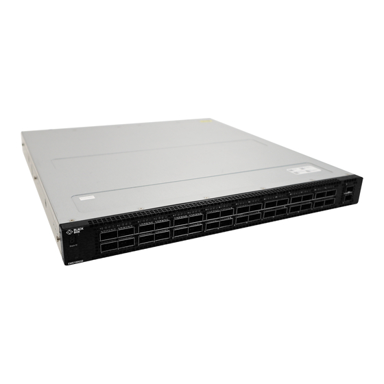
- Page 1 USER MANUAL EMS100G32-R2 EMERALD 100-GIGABIT ETHERNET NETWORK SWITCH, 32-PORT 24/7 TECHNICAL SUPPORT AT 1.877.877.2269 OR VISIT BLACKBOX.COM...
- Page 2 RACK MOUNTING SWITCH GROUND FANS AND AIRFLOW FAN COMBINATIONS POWER STORING COMPONENTS SWITCH INSTALLATION EMS100G32-R2 NEBS COMPLIANCE IMPORTANT INFORMATION GROUND CABLE RACK OR CABINET HARDWARE INSTALLATION RACK MOUNT SAFETY CONSIDERATIONS ONE U READYRAILS INSTALLATION 1U TOOL-LESS MOUNT INSTALLATION TWO-POST FLUSH-MOUNT INSTALLATION...
- Page 3 NEED HELP? LEAVE THE TECH TO US LIVE 24/7 TECHNICAL SUPPORT 1.877.877.2269 SWITCH INSTALLATION 1U FRONT-RACK INSTALLATION DC POWER CONNECTIONS OPTICS INSTALLATION OPTICS REMOVAL SWITCH START UP START UP SEQUENCE AFTER SWITCH PLACEMENT SWITCH REPLACEMENT POWER SUPPLIES COMPONENTS PSU LEDS AC OR DC POWER SUPPLY INSTALLATION AC OR DC POWER SUPPLY REPLACEMENT POWER CABLE CLIP INSTALLATION...
-
Page 4: Nom Statement
NEED HELP? LEAVE THE TECH TO US LIVE 24/7 TECHNICAL SUPPORT 1.877.877.2269 CHASSIS PHYSICAL DESIGN IEEE STANDARDS ELECTROMAGNETIC COMPATIBILITY PRODUCT RECYCLING AND DISPOSAL APPENDIX A: REGULATORY INFORMATION A.1 FCC STATEMENT A.2 CE STATEMENT A.3 ROHS A.4 NOM STATEMENT APPENDIX B: DISCLAIMER/TRADEMARKS B.1 DISCLAIMER B.2 TRADEMARKS USED IN THIS MANUAL 1.877.877.2269... -
Page 5: About This Guide
Š When no cable is connected, visible and invisible laser radiation may emit from the aperture of the optical transceiver ports. Avoid exposure to laser radiation. Do not stare into open apertures. REGULATORY EMS100G32-R2 is represented by the regulatory model E21W and the regulatory type E21W005. 1.877.877.2269 BLACKBOX.COM... - Page 6 The switch includes two hot-swappable AC or DC power supply units (PSUs) and four hot-swappable fan units. Š EMS100G32-R2 is a one-rack unit that includes (32) 100GbE QSFP28 ports and (2) 10GbE SFP+ ports. It supports the following configurations: Š...
- Page 7 SUPPORT 1.877.877.2269 The EMS100G32-R2 switch has one RJ-45 serial console port, one Micro-USB Type A console port, one 10/100/1000 Base-T Ethernet management port, and one USB Type A port for the external storage. Management ports are located on the PSU-side of the switch.
-
Page 8: Physical Dimensions
Š 17.1 x 18.1 x 1.72 inches (434 x 460 x 43.6 mm) (W x D x H) LED DISPLAY The EMS100G32-R2 switch includes LED displays on the I/O side of the switch. This section describes open networking installation environment (ONIE) LED behaviors. Some LED behaviors may change after you install your software. - Page 9 NEED HELP? LEAVE THE TECH TO US LIVE 24/7 EMS100G32-R2 SWITCH TECHNICAL SUPPORT 1.877.877.2269 TABLE-1 EMS100G32-R2 SWITCH LED BEHAVIOR DESCRIPTION Š Solid green—Normal operation Š Flashing green—Booting System Status/Health LED Š Solid yellow—Critical system error Š Flashing yellow—Noncritical system error, fan failure, or power supply failure ...
- Page 10 NEED HELP? LEAVE THE TECH TO US LIVE 24/7 EMS100G32-R2 SWITCH TECHNICAL SUPPORT 1.877.877.2269 TABLE-2 SYSTEM MANAGEMENT ETHERNET PORT LEDS DESCRIPTION Š Off—No link Š Solid green—Link operating at a maximum speed, autonegotiated/forced to Link LED 1000MBase-T mode Š...
- Page 11 NEED HELP? LEAVE THE TECH TO US LIVE 24/7 EMS100G32-R2 SWITCH TECHNICAL SUPPORT 1.877.877.2269 TABLE-4 SFP+ PORT LEDS DESCRIPTION All four LEDs: Š Off—No link Š Solid green—Link operating at maximum speed, 10G Link LED Š Solid yellow—Link operating at a lower speed, 1G ...
- Page 12 NEED HELP? LEAVE THE TECH TO US LIVE 24/7 EMS100G32-R2 SWITCH TECHNICAL SUPPORT 1.877.877.2269 TABLE-6 QSFP28 PORT LEDS (CONTINUED) DESCRIPTION Š Off—No link/activity Š Solid green—Port link operating 2x50G Link LED Š Flashing yellow—Port activity at 2x50G port ...
-
Page 13: Luggage Tag
SUPPORT 1.877.877.2269 MS100G32-R2 SWITCH CONFIGURATIONS You can order the EMS100G32-R2 switch in several different configurations. Š AC or DC Normal Airflow switch: Š One U, 32 x 100GbE ports, two AC or DC power supplies, and four fan subsystems with airflow from the I/O side ... -
Page 14: Site Preparations
LEAVE THE TECH TO US LIVE 24/7 SITE PREPARATIONS TECHNICAL SUPPORT 1.877.877.2269 The EMS100G32-R2 switch is suitable for installation as part of a common bond network (CBN). You can install the switch in: Š Network telecommunication facilities Š Data centers ... - Page 15 Ground the equipment rack to the same ground point the power service in your area uses. The ground path must be permanent. SWITCH GROUND Black Box recommends that you ground your switch. Use the switch in a common bond network (CBN). Connect the grounding cables as described in Switch installation. NOTE: For an AC-powered switch, although the third conductor of the AC power cable provides a ground path, Black Box recommends grounding your switch with a dedicated ground wire.
-
Page 16: Storing Components
Module power is software controlled. You do not see module LEDs when the switch powers up in ONIE. STORING COMPONENTS If you do not install your EMS100G32-R2 switch and components immediately, properly store the switch and all components using these guidelines: Š... -
Page 17: Switch Installation
ESD damage can occur if components are mishandled. Always wear an ESD-preventive wrist or heel ground strap when handling the EMS100G32-R2 switch and components. As with all electrical devices of this type, take all the necessary safety precautions to prevent injury when installing this switch. -
Page 18: Ground Cable
To attach a ground cable to the switch, use the included M4 screws. NOTE: For an AC-powered switch, although the third conductor of the AC power cord provides a ground path, Black Box recommends grounding your switch with a dedicated ground wire. You can order an AC ground lug separately. -
Page 19: Rack Or Cabinet Hardware Installation
You may either place the switch on a rack shelf or mount the switch directly into a 19” wide, EIA-310- E-compliant rack. Rack mounting for the EMS100G32-R2 switch includes four-post, two-post, round threaded holes, or square holes. The ReadyRails system is provided for 1U front-rack and two-post installations. -
Page 20: One U Readyrails Installation
NEED HELP? LEAVE THE TECH TO US LIVE 24/7 SWITCH INSTALLATION TECHNICAL SUPPORT 1.877.877.2269 ONE U READYRAILS INSTALLATION You can install the ReadyRails system using the 1U tool-less square-hole method or one of three possible 1U threaded round-hole methods. The tooled installation methods include two-post flush mount, two-post center mount, or four- post threaded mount. -
Page 21: Tool-Less Mount Installation
NEED HELP? LEAVE THE TECH TO US LIVE 24/7 SWITCH INSTALLATION TECHNICAL SUPPORT 1.877.877.2269 1U TOOL-LESS MOUNT INSTALLATION NOTE: For more installation instructions, see the installation labels attached to the rail assembly. Face the ReadyRails flange ears facing outward. Place one rail between the left and right vertical posts. Align and seat the back flange rail pegs in the back vertical post flange. -
Page 22: Two-Post Flush-Mount Installation
NEED HELP? LEAVE THE TECH TO US LIVE 24/7 SWITCH INSTALLATION TECHNICAL SUPPORT 1.877.877.2269 TWO-POST FLUSH-MOUNT INSTALLATION NOTE: For more installation instructions, see the installation labels attached to the rail assembly. Remove the latch castings from the front side of each ReadyRails assembly, item 1. To remove the two screws from each front flange ear on the switch side of the rail and remove each latch casting, use a Torx screwdriver. -
Page 23: Two-Post Center-Mount Installation
NEED HELP? LEAVE THE TECH TO US LIVE 24/7 SWITCH INSTALLATION TECHNICAL SUPPORT 1.877.877.2269 TWO-POST CENTER-MOUNT INSTALLATION NOTE: For more installation instructions, see the installation labels attached to the rail assembly. Slide the plunger bracket rearward until it clicks into place and secure the bracket to the front post flange with two user-supplied screws, item 1. -
Page 24: Four-Post Threaded Installation
NEED HELP? LEAVE THE TECH TO US LIVE 24/7 SWITCH INSTALLATION TECHNICAL SUPPORT 1.877.877.2269 FOUR-POST THREADED INSTALLATION NOTE: For more installation instructions, see the installation labels attached to the rail assembly. Remove the latch castings from each end of the ReadyRails assemblies. To remove the two screws each latch casting, use a Torx driver. -
Page 25: Front-Rack Installation
TECHNICAL SUPPORT 1.877.877.2269 SWITCH INSTALLATION For the 1U two-post configurations for the EMS100G32-R2, slide the switch into the rails in the same manner as the four-post configurations. 1U FRONT-RACK INSTALLATION Configure the rails that are attached to the switch. NOTE: For more instructions, see the installation instruction labels on the rail. - Page 26 NEED HELP? LEAVE THE TECH TO US LIVE 24/7 SWITCH INSTALLATION TECHNICAL SUPPORT 1.877.877.2269 Line up both switch rails with the previously mounted rack ReadyRails and slide the switch in until it is flush with front of rack. To keep the switch from inadvertently sliding out of the rack and falling, about 3 inches before you fully insert your switch, the rail locking feature engages.
-
Page 27: Dc Power Connections
NEED HELP? LEAVE THE TECH TO US LIVE 24/7 SWITCH INSTALLATION TECHNICAL SUPPORT 1.877.877.2269 DC POWER CONNECTIONS Each DC powered system comes with a set containing a prewired (3-inch 8AWG) power supply connector and a four- screw wiring block, as shown. One set is provided for each DC PSU. SDC wire RTN DC power connector Captive screws (2) -
Page 28: Optics Installation
While continuing to squeeze, pull the power connector from the DC PSU socket. OPTICS INSTALLATION The EMS100G32-R2 switch has SFP+, SFP28, QSFP-DD, and QSFP28 optical ports. CAUTION: ESD damage can occur if components are mishandled. Always wear an ESD-preventive wrist or heel ground strap when handling the EMS100G32-R2 switch and components. -
Page 29: Switch Start Up
1.877.877.2269 SWITCH START UP Supply power to the EMS100G32-R2 switch after it is mounted in a rack or cabinet. Black Box recommends reinspecting your switch before powering it up. Verify the following: Š Optional: The equipment is properly secured to the rack and properly grounded. -
Page 30: Switch Replacement
Black Box support representative. NOTE : Some steps do not apply if you are replacing a different switch or non-Black Box EMC switch. NOTE : ESD damage can occur when components are mishandled. Always wear an ESD-preventive wrist or heel ground strap when handling the switch and accessories. -
Page 31: Power Supplies
SUPPORT 1.877.877.2269 The EMS100G32-R2 switch ships with two AC or DC power supplies. The two power supplies have two air-flow directions—from the I/O to the PSU and from the PSU to the I/O. Two PSUs are required for full redundancy, but the switch can operate with a single PSU. -
Page 32: Ac Or Dc Power Supply Installation
If you use a single PSU, install a blank plate in the other PSU slot. If you are only using one power supply, install the power supply in the first slot, PSU1. Install a blank plate in the second slot, PSU2. Remove the PSU slot cover from the EMS100G32-R2 switch using a small #1 Phillips screwdriver. Remove the PSU from the electro-static bag. -
Page 33: Ac Or Dc Power Supply Replacement
1.877.877.2269 Plug in the appropriate AC 3-prongs cable from the switch PSU to the external power source. Repeat steps 1 through 4 if you have a redundant PSU using the second PSU slot on the EMS100G32-R2 switch. EMS100G320-R2 switch PSU: 1--PSU1 is on the right side of the switch. -
Page 34: Power Cable Clip Installation
NEED HELP? LEAVE THE TECH TO US LIVE 24/7 POWER SUPPLIES TECHNICAL SUPPORT 1.877.877.2269 Disconnect the power cable from the PSU. Use the grab handle to slide the PSU out of the power supply bay. Use the grab handle on the replacement PSU to slide it into the power supply bay. Attach the power cables to the replacement PSU. - Page 35 SUPPORT 1.877.877.2269 The EMS100G32-R2 switch comes from the factory with two PSUs and four fan modules installed in the switch. fan modules and the power supplies, which have integrated fans, are hot-swappable. In addition to the power supply modules, you can order and install fan modules separately.
-
Page 36: Fan Module Installation
FAN MODULE INSTALLATION The fan modules in the EMS100G32-R2 switch are field replaceable. Fan module slots 1 and 2 are on the left side of the switch and fan module slots 3 and 4 are on the right side of the switch. -
Page 37: Management Ports
TECHNICAL SUPPORT 1.877.877.2269 The EMS100G32-R2 switch provides three ports for management and one USB flash drive mount for file transfers. NOTE : The output examples in this section are for reference only. Your output may vary. RJ-45 CONSOLE PORT ACCESS The management ports are on the PSU-side of the switch. -
Page 38: Microusb-B Console Port Access
The MicroUSB-B console port is on the I/O side of the switch. NOTE : The EMS100G32-R2 switches use the Silicon Labs CP2102 USB-B chip. To find the correct USB-B universal asynchronous receiver-transmitter (UART) driver, see the Downloads section of the https://www.silabs.com/products/ development-tools/software/usb-to-uart-bridge-vcp-drivers site. -
Page 39: Usb Storage Mount
BEFORE YOU INSTALL AN OS After powering on the EMS100G32-R2 switch, it goes through a power-on self-test (POST). POST runs every time the switch is initialized and checks the hardware components to determine if the switch is fully operational before booting. -
Page 40: Grub Bootloader Example
During the initial setup, the switch boots to ONIE Install. ONIE Install boots with ONIE Discovery to the console, ONIE:. NOTE : After you have securely installed and powered on the EMS100G32-R2 switch, to configure your switch, see your thirdparty ONIE-compatible OS documentation. -
Page 41: Check Your Switch
NEED HELP? LEAVE THE TECH TO US LIVE 24/7 MANAGEMENT PORTS TECHNICAL SUPPORT 1.877.877.2269 CHECK YOUR SWITCH To confirm that ONIE is working properly, use the onie-sysinfo command. Run the onie-sysinfo command at the ONIE prompt. ONIE SERVICE DISCOVERY ONIE attempts to locate the installer through several discovery methods. To download and run an installer, the ONIE Service Discovery feature follows these steps in order and uses the first successful method found: Search locally attached storage devices for one of the ONIE default installer filenames—for example, onie self... - Page 42 NEED HELP? LEAVE THE TECH TO US LIVE 24/7 MANAGEMENT PORTS TECHNICAL SUPPORT 1.877.877.2269 NOTE : If you have a recovery USB plugged into your switch, you must remove it before using the onie-nos-install command. The ONIE Install environment uses DHCP to assign an IP address to the management interface—eth0. If that fails, it uses the default IP address 192.168.3.10/255.255.255.0.
-
Page 43: Specifications
SUPPORT 1.877.877.2269 This section lists the EMS100G32-R2 switch specifications. CAUTION : Operate the product at an ambient temperature not higher than 113°F (45°C). CAUTION : Lithium battery Caution: There is a danger of explosion if the battery is incorrectly replaced. - Page 44 NEED HELP? LEAVE THE TECH TO US LIVE 24/7 SPECIFICATIONS TECHNICAL SUPPORT 1.877.877.2269 TABLE-9 ENVIRONMENTAL PARAMETERS PARAMETER SPECIFICATIONS 32 to 113°F (0 to 45°C) continuously Operating temperature NOTE: Reduce maximum temperature by 1°F/228 feet (1°C/125 meters) above 3,117 feet (950 meters). Operating humidity 5 to 85% (RH), non-condensing Storage temperature...
-
Page 45: Ieee Standards
LEAVE THE TECH TO US LIVE 24/7 SPECIFICATIONS TECHNICAL SUPPORT 1.877.877.2269 IEEE STANDARDS Š The EMS100G32-R2 switch complies with the following IEEE standards. Š 802.1ab (LLDP) Š 802.1ax (Layer 2) Š 802.1d, 802.1w, 802.1s, 802.1x (Mgmt/Security), 802.3x (Layer 2) ... -
Page 46: Product Recycling And Disposal
1.877.877.2269 PRODUCT RECYCLING AND DISPOSAL You must recycle or discard this switch according to applicable local and national regulations. Black Box encourages owners of information technology (IT) equipment to responsibly recycle their equipment when it is no longer needed. Waste electrical and electronic equipment (WEEE) directive for recovery, recycle and reuse of IT and telecommunications products. -
Page 47: Appendix A: Regulatory Information
NEED HELP? LEAVE THE TECH TO US LIVE 24/7 APPENDIX A: REGULATORY INFORMATION TECHNICAL SUPPORT 1.877.877.2269 A.1 FCC STATEMENT This equipment has been tested and found to comply with the regulations for a Class B digital device, pursuant to Part 15 of the FCC Rules. These limits are designed to provide reasonable protection against harmful interference when the equipment is operated in a commercial environment. - Page 48 NEED HELP? LEAVE THE TECH TO US LIVE 24/7 APPENDIX A: REGULATORY INFORMATION TECHNICAL SUPPORT 1.877.877.2269 A.4 NOM STATEMENT E: El aparato ha sido tirado o su cubierta ha sido dañada. 1. Todas las instrucciones de seguridad y operación deberán ser leídas antes de que el aparato eléctrico sea operado. 2.
-
Page 49: Appendix B: Disclaimer/Trademarks
B.1 DISCLAIMER Black Box Corporation shall not be liable for damages of any kind, including, but not limited to, punitive, consequential or cost of cover damages, resulting from any errors in the product information or specifications set forth in this document and Black Box Corporation may revise this document at any time without notice. - Page 50 NEED HELP? LEAVE THE TECH TO US LIVE 24/7 TECHNICAL SUPPORT 1.877.877.2269 © COPYRIGHT 2022. BLACK BOX CORPORATION. ALL RIGHTS RESERVED. EMS100G32-R2_USER_REV1.PDF...
Need help?
Do you have a question about the EMS100G32-R2 and is the answer not in the manual?
Questions and answers