
Related Manuals for Black Box EMS1G-48


Summary of Contents for Black Box EMS1G-48
- Page 1 HARDWARE INSTALLATION GUIDE EMS1G-48 48-PORT 1G IP NETWORK SWITCH 24/7 TECHNICAL SUPPORT AT 1.877.877.2269 OR VISIT BLACKBOX.COM...
-
Page 2: Table Of Contents
NEED HELP? LEAVE THE TECH TO US LIVE 24/7 TABLE OF CONTENTS TECHNICAL SUPPORT 1.877.877.2269 SAFETY INSTRUCTIONS .................................. 4 1. SPECIFICATIONS ................................... 5 2. OVERVIEW ...................................... 6 2.1 Introduction .......................................6 2.2 Features ........................................6 2.3 What’s Included ......................................6 2.4 Additional Items You May Need ................................6 2.5 Hardware Description ....................................7 2.5.1 Front Panel ........................................... - Page 3 NEED HELP? LEAVE THE TECH TO US LIVE 24/7 TABLE OF CONTENTS TECHNICAL SUPPORT 1.877.877.2269 7. FANS ......................................26 7.1 Components ......................................26 7.2 Fan Module Installation ..................................26 7.3 Fan Module Replacement ..................................27 7.4 After Installing the Switch ..................................27 8. MANAGEMENT PORTS ................................28 8.1 RS-232 Console Port Access ................................28 8.1.1 USB-B Console ........................................28 8.1.2 USB Storage Mount ......................................29...
-
Page 4: Safety Instructions
NEED HELP? LEAVE THE TECH TO US LIVE 24/7 SAFETY INSTRUCTIONS TECHNICAL SUPPORT 1.877.877.2269 This guide provides site preparation recommendations, step-by-step procedures for rack mounting and desk mounting, inserting optional modules, and connecting to a power source. CAUTION: To avoid electrostatic discharge (ESD) damage, wear grounding wrist straps when handling this equipment. WARNING: Only trained and qualified personnel can install this equipment. -
Page 5: Specifications
TECHNICAL SUPPORT 1.877.877.2269 48-PORT 1G NETWORK SWITCH (EMS1G-48) SPECIFICATIONS APPROVALS Environmental Compliances: Japan: VCCI V3/2009 Class A; USA: FCC CFR 47 Part 15, Subpart B:2009, Class A; RoHS EMI Certifications: Australia/New Zealand: AS/NZS CISPR 32: Class A; Canada: ICES-003, Issue-4, Class A; Europe: EN 55032: 2015+A1:2007 (CISPR 32);... -
Page 6: Overview
TECHNICAL SUPPORT 1.877.877.2269 2.1 INTRODUCTION The EMS1G-48 is a low-cost top-of-rack (ToR) switch for 1 Gbps links to servers and 10 Gbps uplinks to the 40 Gbps switching fabric in the core. 2.2 FEATURES Š Forty-eight 10/100/1000BASE-T RJ-45 ports Š... -
Page 7: Hardware Description
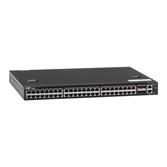
NEED HELP? LEAVE THE TECH TO US LIVE 24/7 CHAPTER 2: OVERVIEW TECHNICAL SUPPORT 1.877.877.2269 2.5 HARDWARE DESCRIPTION 2.5.1 FRONT PANEL Figure 2-1 shows the front panel of the switch. Table 2-1 describes its components. FIGURE 2-1. FRONT PANEL OF THE SWITCH TABLE 2-1. -
Page 8: Back Panel
NEED HELP? LEAVE THE TECH TO US LIVE 24/7 CHAPTER 2: OVERVIEW TECHNICAL SUPPORT 1.877.877.2269 2.5.2 BACK PANEL Figure 2-2 shows the back panel of the switch. Table 2-3 describes its components. FIGURE 2-2. BACK PANEL OF THE SWITCH TABLE 2-3. BACK PANEL COMPONENTS NUMBER IN COMPONENT DESCRIPTION... -
Page 9: Led Indicators
1.877.877.2269 2.5.3 LED INDICATORS The EMS1G-48 includes LED displays on the I/O side of the switch. This section describes open networking installation environment (ONIE) LED behaviors. Some LED behaviors may change after you install your software. The following EMS1G-48 switch LED behavior is seen during ONIE operations. - Page 10 NEED HELP? LEAVE THE TECH TO US LIVE 24/7 CHAPTER 2: OVERVIEW TECHNICAL SUPPORT 1.877.877.2269 TABLE 2-4. LEDS ON THE SWITCH NUMBER IN NAME OF LED DESCRIPTION FIGURE 2-3 • Off - No Link Management Ethernet • Solid green - Link on 1 Gbps speed Port Link LED •...
-
Page 11: Preparing The Site
Ground the equipment rack to the same ground point the power service in your area uses. The ground path must be permanent. 3.4 SWITCH GROUND Black Box recommends you ground your switch. Use the EMS1G-48 in a common bond network (CBN). Connect the grounding cables as described in Install the Switch. -
Page 12: Fans And Airflow
Š For proper ventilation, position the EMS1G-48 in an equipment rack or cabinet with a minimum of 5 inches (12.7 cm) of clearance around the exhaust vents. When you install two EMS1G-48 switches near each other, to permit proper airflow, position the two chassis at least 5 inches (12.7 cm) apart. -
Page 13: Nebs Compliance
GR-1089-CORE, Issue 6) and they require isolation from the exposed OSP cabling. Adding primary protectors is not sufficient protection to connect these interfaces metallically to OSP wiring. WARNING: If you install and connect the EMS1G-48 switch to a commercial AC power source, you must connect the switch to an external special protection device (SPD). -
Page 14: Installing The Switch
NEED HELP? LEAVE THE TECH TO US LIVE 24/7 CHAPTER 5: INSTALLING THE SWITCH TECHNICAL SUPPORT 1.877.877.2269 NOTE: Before unpacking the switch, inspect the container and immediately report any evidence of damage. 5.1 UNPACKING STEPS 1. Place the container on a clean, flat surface and cut all straps securing the container. 2. -
Page 15: Rails System Installation
5.2.2 RAILS SYSTEM INSTALLATION The rackmounting system is provided to easily configure your rack for installation of your EMS1G-48 switch. You can install the rail system using the 1U tool-less method or one of three 1U tooled methods—two-post flush mount, two-post center mount or four-post threaded. - Page 16 NEED HELP? LEAVE THE TECH TO US LIVE 24/7 CHAPTER 5: INSTALLING THE SWITCH TECHNICAL SUPPORT 1.877.877.2269 TWO-POST FLUSH MOUNT INSTALLATION 1. For this configuration, remove the castings from the front side of each rail assembly, item 1. Use a Torx screwdriver to remove the two screws from each front flange ear on the switch side of the rail and remove each casting. Retain the castings for future rack requirements.
- Page 17 NEED HELP? LEAVE THE TECH TO US LIVE 24/7 CHAPTER 5: INSTALLING THE SWITCH TECHNICAL SUPPORT 1.877.877.2269 TWO-POST CENTER MOUNT INSTALLATION 1. Slide the plunger bracket rearward until it clicks into place and secure the bracket to the front post flange with two user-supplied screws, item 1.
- Page 18 NEED HELP? LEAVE THE TECH TO US LIVE 24/7 CHAPTER 5: INSTALLING THE SWITCH TECHNICAL SUPPORT 1.877.877.2269 FOUR-POST THREADED INSTALLATION 1. For this configuration, remove the flange ear castings from each end of the rail assemblies. To remove the two screws from each flange ear and remove each casting, use a Torx driver, item 1. Retain the castings for future rack requirements.
-
Page 19: Switch Installation
1U FRONT-RACK INSTALLATION Configure the rails that are attached to the switch. 1. Attach the inner chassis members switch rails to the EMS1G-48 switch. Item 3 shows the detail for the front standoff with the locking tab. FIGURE 5-5. SWITCH RAILS ATTACHMENT 2. -
Page 20: Ground Cable
NOTE: Do not the use the mounted rails as a shelf or a workplace. 5.4 GROUND CABLE Black Box recommends that you ground your switch. To attach the ground cable to the chassis, use a single M4x0.7 screw. The cable itself is not included with the switch. -
Page 21: Optics Installation
5.7 POWERING UP THE SWITCH Supply power to the switch after it is mounted in a rack or cabinet. Black Box recommends reinspecting your switch before powering up. Verify the following: Š The equipment is properly secured to the rack and properly grounded, optional. - Page 22 NEED HELP? LEAVE THE TECH TO US LIVE 24/7 CHAPTER 5: INSTALLING THE SWITCH TECHNICAL SUPPORT 1.877.877.2269 Power up sequence When the switch powers up, the fans immediately come on at high speed. The fan speed slows as the switch continues to boot up. 1.877.877.2269 BLACKBOX.COM...
-
Page 23: Power Supplies
• AC power supply with integrated fan The EMS1G-48 switch includes an AC power supply with airflow from the I/O side to the PSU side. Two PSUs are required for full redundancy, but the switch can operate with a single PSU. -
Page 24: Ac Power Supply Installation
PSU. NOTE: If you use a single PSU, install a blank plate in the other PSU slot. If you are only using one power supply, Black Box recommends installing the power supply in the first slot (PSU1) and installing a blank plate in the second slot (PSU2). -
Page 25: Ac Power Supply Replacement
NOTE: If a PSU fails, you must replace the entire unit. There are no field serviceable components in the PSU. To request a hardware replacement, contact Black Box Technical Support at 877-877-2269 or info@blackbox.com NOTE: If you use a single PSU, install a blank plate in the other PSU slot. If you are only using one power supply, we recommend installing the power supply in the first slot (PSU1) and installing a blank plate in the second slot (PSU2). -
Page 26: Fans
CAUTION: Check the fans at six-month intervals and replace them as necessary. Regularly monitor the speeds of the fans to accurately determine replacement intervals. 7.1 COMPONENTS The following are the EMS1G-48 fan components. • EMS1G-48 Fan module • EMS1G-48 Fan module—Reverse flow FIGURE 7-1. -
Page 27: Fan Module Replacement
NEED HELP? LEAVE THE TECH TO US LIVE 24/7 CHAPTER 7: FANS TECHNICAL SUPPORT 1.877.877.2269 7.3 FAN MODULE REPLACEMENT CAUTION: Complete steps 1 and 2 within one minute or the switch powers down. 1. Slide the fan module out of the bay. 2. -
Page 28: Management Ports
NEED HELP? LEAVE THE TECH TO US LIVE 24/7 CHAPTER 8: MANAGEMENT PORTS TECHNICAL SUPPORT 1.877.877.2269 Besides the 10/100/1000BASE-T RJ-45 ports, the switch provides several ports for management and storage. 8.1 RS-232 CONSOLE PORT ACCESS The RS-232 console port is on the I/O-side of the switch chassis, as shown. FIGURE 8-1. -
Page 29: Usb Storage Mount
NOTE: Before starting this procedure, be sure you have a terminal emulation program already installed on your PC. You will need to install the appropriate drivers to support the USB-B port. For assistance, contact Black Box Technical Support at 877-877-2269 or info@blackbox.com to download the drivers. -
Page 30: Before You Install An Os
NEED HELP? LEAVE THE TECH TO US LIVE 24/7 CHAPTER 8: MANAGEMENT PORTS TECHNICAL SUPPORT 1.877.877.2269 For USB storage: Disk /dev/sdb: 30.9 GB, 30942946304 bytes 64 heads, 32 sectors/track, 29509 cylinders Units = cylinders of 2048 * 512 = 1048576 bytes Device Boot Start End Blocks... -
Page 31: Example Of The Grub Bootloader
ONIE: Update ONIE For downloading and updating ONIE from a URL ONIE: Embed ONIE For downloading and updating ONIE from a URL and erases any installed O ONIE: Diag ONIE Run Diagnostic package for EMS1G-48 Run Black Box Networking Diagnostic package for <platform>... - Page 32 NEED HELP? LEAVE THE TECH TO US LIVE 24/7 CHAPTER 8: MANAGEMENT PORTS TECHNICAL SUPPORT 1.877.877.2269 Examples of the ONIE ifconfig eth0 Commands If none of the ONIE Service Discovery methods are successful, you can disable this using the onie-discovery-stop command. You can install an operating system manually from HTTP, FTP, or TFTP using the onie-nos-install <URL>...
-
Page 33: Troubleshooting
If you determine that your switch is malfunctioning, do not attempt to alter or repair the unit. It contains no user-serviceable parts. Contact Black Box Technical Support at 877-877-2269 or info@blackbox.com. Before you do, make a record of the history of the problem. We will be able to provide more efficient and accurate assistance if you have a complete description, including: Š... -
Page 34: Appendix A. Regulatory Information
NEED HELP? LEAVE THE TECH TO US LIVE 24/7 APPENDIX A: REGULATORY INFORMATION TECHNICAL SUPPORT 1.877.877.2269 A.1 USA FEDERAL COMMUNICATIONS COMMISSION STATEMENT This equipment has been tested and found to comply with the limits for a Class A digital device, pursuant to Part 15 of the FCC rules. -
Page 35: Nom Statement
NEED HELP? LEAVE THE TECH TO US LIVE 24/7 APPENDIX A: REGULATORY INFORMATION TECHNICAL SUPPORT 1.877.877.2269 A.2 NOM STATEMENT 1. Todas las instrucciones de seguridad y operación deberán ser leídas antes de que el aparato eléctrico sea operado. 2. Las instrucciones de seguridad y operación deberán ser guardadas para referencia futura. 3. -
Page 36: European Union Emc Directive Conformance Statement
This product is in conformity with the protection requirements of EU Council Directive 2004/108/EC on the approximation of the laws of the Member States relating to electromagnetic compatibility. Black Box can not accept responsibility for any failure to satisfy the protection requirements resulting from a non-recommended modification of this product, including the fitting of non- Black Box option cards. -
Page 37: Korean Certification Of Compliance
NEED HELP? LEAVE THE TECH TO US LIVE 24/7 APPENDIX A: REGULATORY INFORMATION TECHNICAL SUPPORT 1.877.877.2269 A.5 KOREAN CERTIFICATION OF COMPLIANCE A.6 SAFETY CERTIFICATIONS AND COMPLIANCE AGENCY CERTIFICATIONS Š CUS UL 60950-1, 2nd Edition – Meets or exceeds Hi Pot and Ground Continuity testing per UL 60950-1. Š... -
Page 38: Immunity
A.8 PRODUCT RECYCLING AND DISPOSAL (WEEE) You must recycle or discard this system according to applicable local and national regulations. Black Box encourages owners of information technology (IT) equipment to responsibly recycle their equipment when it is no longer needed. -
Page 39: Appendix B. Disclaimer/Trademarks
B.1 DISCLAIMER Black Box Corporation shall not be liable for damages of any kind, including, but not limited to, punitive, consequential or cost of cover damages, resulting from any errors in the product information or specifications set forth in this document and Black Box Corporation may revise this document at any time without notice. - Page 40 NEED HELP? LEAVE THE TECH TO US LIVE 24/7 TECHNICAL SUPPORT 1.877.877.2269 © COPYRIGHT 2018. BLACK BOX CORPORATION. ALL RIGHTS RESERVED. EMS1G-48_INSTALL_REV1.PDF...
Need help?
Do you have a question about the EMS1G-48 and is the answer not in the manual?
Questions and answers