Table of Contents
Advertisement
AlertWerks
ServSensor Jr. and ServSensors
™
Monitor environmental variations, power,
physical threats, and security.
Includes a proprietary operating system that is similar to Linux
stack, Web server, e-mail, and full SNMP functionality.
Order toll-free in the U.S.: Call 877-877-BBOX (outside U.S. call 724-746-5500)
Customer
FREE technical support 24 hours a day, 7 days a week: Call 877-877-2269 or fax 724-746-0746
Support
Mailing address: Black Box Corporation, 1000 Park Drive, Lawrence, PA 15055-1018
Information
Web site: www.blackbox.com • E-mail: info@blackbox.com
EME102A-R3 EME106A-R2
EME103A-R3 EME108A-R3 EME111A-60-R2
EME104A-R3 EME109A-R3
EME105A-R2 EME110A-R3
EME111A-20-R3
EME113A-20-R3
EME113A-60-R2
EME112A-20-R3
EME152A-R2
EME112A-60-R2 EME153A-R2
, with TCP/IP
®
EME154A-R2
EME155A-R2
EME158A
Advertisement
Table of Contents

Related Manuals for Black Box AlertWerks EME102A-R3


Summary of Contents for Black Box AlertWerks EME102A-R3
- Page 1 Order toll-free in the U.S.: Call 877-877-BBOX (outside U.S. call 724-746-5500) Customer FREE technical support 24 hours a day, 7 days a week: Call 877-877-2269 or fax 724-746-0746 Support Mailing address: Black Box Corporation, 1000 Park Drive, Lawrence, PA 15055-1018 Information Web site: www.blackbox.com • E-mail: info@blackbox.com...
- Page 2 Trademarks Used in this Manual Trademarks Used in this Manual Black Box and the Double Diamond logo are registered trademarks, and AlertWerks is a trademark, of BB Technologies, Inc. CA-Unicenter is a registered trademark of CA, Inc. GNU is a trademark of Free Software Foundation.
- Page 3 FCC and IC RFI Statements Federal Communications Commission and Industry Canada Radio Frequency Interference Statements This equipment generates, uses, and can radiate radio-frequency energy, and if not installed and used properly, that is, in strict accordance with the manufacturer’s instructions, may cause inter ference to radio communication. It has been tested and found to comply with the limits for a Class A computing device in accordance with the specifications in Subpart B of Part 15 of FCC rules, which are designed to provide reasonable protection against such interference when the equipment is operated in a commercial environment.
- Page 4 NOM Statement Instrucciones de Seguridad (Normas Oficiales Mexicanas Electrical Safety Statement) 1. Todas las instrucciones de seguridad y operación deberán ser leídas antes de que el aparato eléctrico sea operado. 2. Las instrucciones de seguridad y operación deberán ser guardadas para referencia futura. 3.
-
Page 5: Table Of Contents
Table of Contents Table of Contents 1. Specifications..................................6 2. Overview ..................................8 2.1 Introduction ................................8 2.1.1 What is the AlertWerks ServSensor? ....................... 8 2.1.2 Available Models ............................. 8 2.1.3 How to Use this Manual ..........................9 2.2 Features ..................................9 2.3 What’s Included ................................ -
Page 6: Specifications
Chapter 1: Specifications 1. Specifications Color — EME102A-R3–EME104A-R3, EME152A-R2–EME154A-R2: Blue; EME105A-R2–EME106A-R2, EME155A-R2, EME108A-R3–EME110A-R3, EME158A, EME111A-20-R3, EME111A-60-R2, EME112A-20-R3, EME112A-60-R2, EME113A-20-R3, EME113A-60-R2,: Black Default IP Address — 192.168.0.100 Enclosure — EME102A-R3–EME104A-R3, EME152A-R2–EME154A-R2: Plastic housing; EME105A-R2–EME106A-R2, EME155A-R2, EME158A, EME108A-R3–EME110A-R3, EME111A-20-R3, EME111A-60-R2, EME112A-20-R3, EME112A-60-R2, EME113A-20-R3, EME113A-60-R2: Steel housing Mounting —... - Page 7 Chapter 1: Specifications Size — EME102A-R3–EME104A-R3, EME152A-R2–EME154A-R2: 0.5"H x 2.5"W x 1.25"D (1.3 x 6.3 x 3.2 cm); EME105A-R2–EME106A-R2: EME108A-R3–EME110A-R3, EME155A-R2, EME158A: 1.8"H (1U) x 8.5"W x 5.4"D (4.6 x 21.6 x 13.7 cm), EME111A-20-R3–EME112A-20-R3, EME112A-60-R2–EME113A-60-R2: 1.7"H (1U) x 18"W x 5"D (4.3 x 45.7 x 12.7 cm) Weight —...
-
Page 8: Overview
Chapter 2: Overview 2. Overview 2.1 Introduction 2.1.1 What is the AlertWerks ServSensor? The AlertWerks ServSensors are intelligent devices for monitoring environmental variables, power, physical threats, and security. The units are IP based and have a Web interface for configuration. Included in this is a TCP/IP stack, Web server, full SNMP, and e-mail support. -
Page 9: How To Use This Manual
• Optional IEEE 802.3af Power over Ethernet (PoE) compliant (EME152A-R2, EME153A-R2, and EME154A-R2 only). • 100-Mbps full-duplex Ethernet port. 2.3 What’s Included Your package should include the following items. If anything is missing or damaged, contact Black Box Technical Support at 724-746-5500 or info@blackbox.com. EME102A-R3: •... - Page 10 Chapter 2: Overview EME103A-R3: • ServSensor Jr. • Temperature Sensor (EME1T1-001) • CD containing this user‘s manual in PDF format • (1) power supply • (1) RJ-45 to RJ-45 patch cord, 5-ft. (1.5-m) EME104A-R3: • ServSensor Jr. • Dual Temperature/Humidity Sensor (EME1TH1-001) •...
- Page 11 Chapter 2: Overview EME108A-R3: • ServSensor 8 • Power supply • (1) 5-ft. (1.5-m) RJ-45 to RJ-45 cable • (1) set of rackmount brackets with hardware • CD containing this user‘s manual in PDF format EME109A-R3: • ServSensor 8 • Temperature Sensor with 1-ft. (3.2-m) cable (EME1T1-001) •...
- Page 12 Chapter 2: Overview EME112A-20-R3: • ServSensor 8 with 20 dry contact ports • Temperature Sensor with 1-ft. (3.2-m) cable (EME1T1-001) • (1) 5-ft. (1.5-m) RJ-45 to RJ-45 cable • (4) terminal blocks (installed) • (1) set of rackmount brackets with hardware •...
-
Page 13: Hardware Description
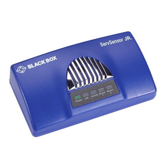
Chapter 2: Overview 2.4 Hardware Description 2.4.1 ServSensor Jr. (EME102A-R3, EME103A-R3, EME104A-R3, EME152A-R2, EME153A-R2, EME154A-R2) Figures 2-1 and 2-2 show the front and top panels of the ServSensor Jr. Table 2-2 describes its components. 5V DC Figure 2-1. ServSensor Jr. front panel. Figure 2-2. -
Page 14: Servsensor 4 (Eme105A-R2, Eme106A-R2, Eme155A-R2)
Chapter 2: Overview 2.4.2 ServSensor 4 (EME105A-R2, EME106A-R2, EME155A-R2) Figures 2-3 and 2-4 show the front and back panels of the ServSensor 4. Table 2-3 describes its components. Figure 2-3. ServSensor 4 front panel. 5V DC Figure 2-4. ServSensor 4 back panel. Table 2-3. -
Page 15: Servsensor 8 (Eme108A-R3, Eme109A-R3, Eme110A-R3, Eme158A)
Chapter 2: Overview 2.4.3 ServSensor 8 (EME108A-R3, EME109A-R3, EME110A-R3. EME158A) Figures 2-5 and 2-6 show the front and back panels of the ServSensor 8. Table 2-4 describes its components. Figure 2-5. ServSensor 8 front panel. 5V DC Figure 2-6. ServSensor 8 back panel. Table 2-4. -
Page 16: Servsensor X20 (Eme111A-20-R3, Eme111A-60-R2, Eme112A-20-R3, Eme112A-60-R2, Eme113A-20-R3, Eme113A-60-R2)
Chapter 2: Overview 2.4.4 ServSensor X20 (EME111A-20-R3, EME111A-60-R2, EME112A-20-R3, EME112A-60-R2, EME113A-20-R3, EME113A-60-R2) Figures 2-7 and 2-8 show the front and back panels of the ServSensor 8 X20. Table 2-5 describes its components. Figure 2-7. ServSensor 8 X20 front panel. 5V DC 9 10 11 12 Figure 2-8. -
Page 17: Servsensor 8-X20 20 Extra Dry Contact Inputs
Chapter 2: Overview 2.4.5 ServSensor 8-X20 20 Extra Dry Contact Inputs The 20 extra dry contact inputs on, for example, the ServSensor with 20 or 60 DC inputs, can be configured as inputs only up to 5 volts in normal operation. In opto-isolation mode, they can input up to 30 volts DC. This will protect these inputs and the unit from high voltages and spikes. -
Page 18: Installation
Chapter 3: Installation 3. Installation 3.1 Assigning an IP Address These units are plug-and-play devices that will easily connect to your existing network setup. Every unit ships with a default IP address. This is 192.168.0.100. To install your unit, you must first assign it an IP address to match your current network configuration. - Page 19 Chapter 3: Installation 3. You will now be presented with the following login screen. Figure 3-2. Login screen. 4. After logging in, you will be taken to the Main Summary page. 877-877-2269 | blackbox.com Page 19...
- Page 20 Chapter 3: Installation Figure 3-3. Main Summary page. 5. From the summary page, select the “Network” tab. Type in your new IP address, then click “Save.” Figure 3-4. Input New Address screen. 877-877-2269 | blackbox.com Page 20...
-
Page 21: Testing Your New Ip Address
Chapter 3: Installation 3.2 Testing your New IP Address You now need to test that your new IP address has been assigned successfully. You will do this via the “ping” command. 1. Click “Start/Run……” Enter the IP address to ping, then press “Enter.” Figure 3-5. -
Page 22: Upgrading The Firmware
We often release new firmware with added capabilities, so we recommend that you upgrade to the latest firmware. To do this, contact Black Box Technical Support at 724-746-5500 or info@blackbox.com and have the MAC address of the hub available. This can be found on a sticker on the base of your unit. - Page 23 Chapter 3: Installation 1. When you download your firmware, it will come in a zip package. Extract this to your desktop into a folder named firmware. When you open this folder you will see something like the following: Figure 3-7. Firmware screen. You can see one of these files is a program named IPSet.
- Page 24 Chapter 3: Installation 2. When IPSet loads, you will be met with a screen similar to this: Figure 3-8. Firmware Upgrade screen. 3. Select “firmware upgrade.” 4. Type in the IP address of your unit. 5. Type in your administrator password . 6.
- Page 25 Contact Black Box Technical Support at 724-746-5500 or info@blackbox.com. If you try to update your unit and receive an error in the IPSet utility, then you will need to update your unit. Contact Black Box Technical Support at 724-746-5500 or info@blackbox.com for details.
- Page 26 Chapter 3: Installation Figure 3-10. Upgrade Firmware screen. 877-877-2269 | blackbox.com Page 26...
-
Page 27: Setting Up A Sensor And Downloading Sensor Data
Chapter 4: Setting Up a Sensor and Downloading Sensor Data 4. Setting up a Sensor and Downloading Sensor Data For the purposes of this manual and tutorials, we will cover setting up a dual temperature/humidity sensor. The first part of the tutorial will cover the basic installation and settings for the sensor. - Page 28 Chapter 4: Setting Up a Sensor and Downloading Sensor Data 4. From this page, select the “Sensors” tab. This will bring you to the following page: Figure 4-2. Sensors screen. In this example, we have selected the humidity sensor from the sensor menu on the left. The sensors highlighted in green indicate that they are currently connected to the unit.
- Page 29 Chapter 4: Setting Up a Sensor and Downloading Sensor Data Figure 4-3. Humidity Sensor Settings screen. 5. This window is used for configuring the sensor’s parameters. These parameters are explained below: Description—The name of the sensor. Use a meaningful name such as “humidity sensor office1” Go Online/Offline—This takes the sensor on or offline without unplugging it from the unit.
-
Page 30: Downloading Sensor Data
Chapter 4: Setting Up a Sensor and Downloading Sensor Data Figure 4-4. Sensor settings screen. Sensor Status Filters—By clicking on the “Sensors Status Filters” button shown in the image in Figure 4-3, you can then adjust the continuous time the sensor is in a warning, error, or normal state before the unit sends the alerts (see Figure 4-4). This feature was added to eliminate false warnings. - Page 31 Chapter 4: Setting Up a Sensor and Downloading Sensor Data Figure 4-5. Download Data screen. Using remote syslog to download sensor data Another way to get and log all the data in real time from the unit is to use the remote syslog on the unit. You can use the remote system log feature to push out the syslog in real time to a remote server, or PC, then this information can be imported into a data base or other program.
- Page 32 Chapter 4: Setting Up a Sensor and Downloading Sensor Data Figure 4-6. Set UDP. Set the remote syslog in the ServSensor. The remote syslog IP address is the IP address of the PC that has the Kiwi remote syslog program running on it. The remote syslog port is the same port on the remote syslog program. It should be showing you the syslog in real time, and any entry that is logged in the unit should appear on your server.
-
Page 33: Notifications
Chapter 5: Notifications 5. Notifications 5.1 Setting Up a Trap The ServSensor can send an SNMP trap message to two different hosts. Whenever the status changes for a sensor that is on-line, a trap message can be sent. To get to the entry point of this tutorial, complete the following: 1. -
Page 34: Setting Up E-Mail Notifications
Chapter 5: Notifications 4. The traps have various fields you need to set. These are explained next. Figure 5-2. Trap 1 screen. Send Trap—Toggles whether the SNMP trap is on or off. Destination IP—The destination IP address that the trap message will be sent to. Community—This is the community of the host that will receive this trap. - Page 35 Chapter 5: Notifications Figure 5-3. Mail Parameters Setup screen. 5. You can now set up the individual e-mail options from the fields shown next. 877-877-2269 | blackbox.com Page 35...
- Page 36 Chapter 5: Notifications Figure 5-4. Mail Settings screen. Send Mail—This toggles the send e-mail option on or off. SMTP Server—The address of your SMTP server. SMTP Authentication—Check this option if your SMTP server requires authentication. SMTP Server Login Name—The user name to log in to your SMTP server. SMTP Server Password—The password used to log in to your SMTP server.
- Page 37 Chapter 5: Notifications Figure 5-5. E-mail Address Configuration screen. Mail From—The e-mail address that you want the e-mail to appear from. Because of anti-spam features of some SMTP servers, this address must be authorized on the SMTP server; otherwise, the server may deny the email. Mail Recipient—The email address of the person you want to send the email to.
-
Page 38: System Settings
Chapter 6: System Settings 6. System Settings 6.1 Network Settings The Network Settings page allows you to change network settings, such as the IP address etc., for your unit. To get to the entry point of this tutorial, complete the following: 1. - Page 39 Chapter 6: System Settings 5. Once on this page, you can set up the network settings as indicated below: Figure 6-2. Network Settings screen. IP Address—Use this to change the IP address of your unit. Subnet Mask—Use this to assign the subnet mask of your unit. Default Gateway—Assign the default gateway of your device.
-
Page 40: System Tab
Chapter 6: System Settings RTC Battery Status—This field displays the status of the real-time clock battery on the unit. If the status displays “Bad,” you must replace the battery; otherwise, when the ServSensor does not have power, the clock will stop running. Re-configure the system time settings on every reboot. - Page 41 Chapter 6: System Settings 4. When you arrive at the Settings page, you will see the following screen: Figure 6-4. Settings screen. 5. The first section is entitled “System Settings.” 877-877-2269 | blackbox.com Page 41...
- Page 42 Chapter 6: System Settings Figure 6-5. System Settings screen. System Description—This is an MIB II value set when the microcode for the unit was installed. It includes the build time and ver- sion of the microcode. This is a read-only field. System Name/Location/Contact—These are used to identify the system.
- Page 43 Figures 6-5 and 6-6. This System page will also show in the ServSensor 8 interface on units shipped before July 1, 2011. For current screen explanations, contact Black Box Technical Support at 724-746-5500 or info@blackbox.com. NOTE: To allow the user to log in without having to enter a password, use “public” in the SNMP get.
- Page 44 Chapter 6: System Settings Figure 6-7. Setting SNMP passwords. NOTE: The “j” on the end of the firmware version above confirms that the unit has the newer mega256 memory chip. The ServSensor with the newer mega256 memory chip allows you to separate the SNMP communities from the Web interface login passwords.
- Page 45 Chapter 6: System Settings SNMP Port—Use this option to reset the SNMP port setting to its default. SNMP Trap Port—Use this option to reset the SNMP trap port to its default setting. NOTE : Your SNMP port default is 161 and the SNMP trap port default is 162. You can set your SNMP ports with the following commands: snmpset -m all -v 1 -c <community>...
-
Page 46: Making Your Unit Visible To The Internet
Chapter 7: Making Your Unit Visible to the Internet 7. Making Your Unit Visible to the Internet So far the manual has simply covered the basic setup. The setup we have just created will allow you to access your unit on a Local Area Network (LAN). -
Page 47: Frequently Asked Questions (Faqs)
Chapter 8: Frequently Asked Questions (FAQs) 8. Frequently Asked Questions (FAQs) Question: How does the ServSensor record the sensor data and how much can it store? Answer: The ServSensor will record and store the changes for the dry contacts and sensors because the unit’s hardware has a data logger where it stores this data in memory. - Page 48 When the ServSensor is powered up, the IPSet will capture its IP address, then you will be able to click on the flashing button to open the Web interface. You can download the IPSet utility by logging into the Black Box Web site (www.blackbox.com) with your unit’s MAC ID.
- Page 49 Chapter 8: Frequently Asked Questions (FAQs) Question: I have assigned the gateway IP, and when I click “Save,” it reverts back to the default IP. What should I do? Answer: This happens when the device can’t find the IP entered. When the IP is entered, the device searches for the IP and will accept it if it is found, or else it will revert back to the default IP.
- Page 50 ServSensor in real time. You can collect an unlimited number of readings and you can collect data from multiple ServSensors simultaneously. You can download this from the Black Box Web site by first logging in with your unit’s MAC ID.
- Page 51 NOTES 877-877-2269 | blackbox.com Page 51...
- Page 52 About Black Box Black Box provides an extensive range of networking and infrastructure products. You’ll find everything from cabinets and racks and power and surge protection products to media converters and Ethernet switches all supported by free, live 24/7 Tech support available in 60 seconds or less.
Need help?
Do you have a question about the AlertWerks EME102A-R3 and is the answer not in the manual?
Questions and answers