
Related Manuals for Thytronic NA30


Summary of Contents for Thytronic NA30
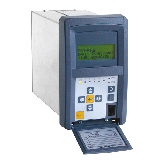
- Page 1 NA30 PHASE & RESIDUAL OVERCURRENT, GROUND DIRECTIONAL, THERMAL IMAGE, RESIDUAL OVERVOLTAGE MANUAL NA10 - Manual - 04 - 2022...
-
Page 2: Table Of Contents
T A B L E O F C O N T E N T S T A B L E O F C O N T E N T S 1 INTRODUCTION Scope and liability ......................................5 Applicability ........................................5 Conformity ........................................5 Copyright ...........................................5 Warranty ...........................................5 Safety recommendations ....................................5... - Page 3 3.9 METERING..........................................25 Accuracy (type tests)....................................25 Measures ........................................25 4 FUNCTION CHARACTERISTICS 4.1 HARDWARE DESCRIPTION .....................................26 Power supply board ......................................27 CPU board ........................................27 Input board ........................................27 MMI (keyboard, LED and display) ................................27 4.2 SOFTWARE DESCRIPTION ..................................... 28 Base software ....................................... 28 Real-time operating system ..................................28 Task ..........................................
- Page 4 6.4 NOMINAL CURRENT I AND I SETTING ............................... 149 6.5 LED ALLOCATION ......................................153 6.6 FINAL OPERATIONS ...................................... 153 7 PROGRAMMING AND SETTINGS 7.1 SW ThyVisor ........................................154 ThyVisor installation ....................................154 ThyVisor use .........................................154 7.2 MMI (Man Machine Interface) ..................................155 Reading variables (READ) ..................................155 Setting modifying (SET) ....................................155 TEST ..........................................157 COMMUNICATION ......................................157...
-
Page 5: Introduction
I N T R O D U C T I O N Scope and liability This document describes the functions, the technical data of NA30 devices; instructions for mount- ing, setting and commissioning are included. This manual has been checked out, however, deviations from the description cannot be completely ruled out, so that no liability in a legal sense for correctness and completeness of the information or from any damage that might result from its use is formally disclaimed. -
Page 6: Product Identification
• Test label with following informations: data, serial number and test operator signature. Environment The NA30 device must be employed according to the environment conditions shown (see technical data). In case of different environment conditions, appropriate provisions must be provided (conditioning system, humidity control, etc...). - Page 7 Setting and monitoring software Log file A text file that lists actions that have occurred (ThyVisor). J2SE Java Platform Standard Edition Subnet Mask (Ethernet nomenclature) Software Firmware Upgrade Firmware upgrade eXtensible Markup Language NA30 - Manual - 04 - 2022 PREFACE...
- Page 8 ON delay timer with reset ( delay) OUTPUT RESET RESET INPUT ON delay timer without reset ( delay) OUTPUT INPUT DROP OFF delay timer (dropout) without reset ( delay) DROP DROP OUTPUT Symbols.ai NA30 - Manual - 04 - 2022 PREFACE...
- Page 9 RESET INPUT Minimum pulse width operation for output relays ( OUTPUT INPUT Latched operating mode for output relays and LEDs Latched OUTPUT INPUT Pulse operating mode for output relays OUTPUT Symbols1 .ai NA30 - Manual - 04 - 2022 PREFACE...
-
Page 10: General
G E N E R A L Preface The relay type NA30 can be used in radial networks as feeder or power transformer protection: • On long feeders in ungrounded or Petersen coil and/or high resistance grounded systems. • On the BT side of parallel connect transformers that are protected with differential element with any grounded systems. -
Page 11: Main Features
(start-trip). • The event recorder (SER) runs continuously capturing in circular mode the last three hundred events upon trigger of binary input/output. • Digital fault recorder (DFR) in COMTRADE format (oscillography). NA30 - Manual - 04 - 2022 GENERAL... -
Page 12: Technical Data
2.0 kV • Ring wave differential mode 1.0 kV Reference standards EN 60255-22-2 IEC 60255-22-2 EN 61000-4-2 IEC 61000-4-2 Electrostatic discharge • Contact discharge 6 kV • Air discharge 8 kV NA30 - Manual - 04 - 2022 TECHNICAL DATA... -
Page 13: Emission
10...95 % Atmospheric pressure 70...110 kPa ‡ Safety Reference standards EN 61010-1 Safety requirements for electrical equipment for measurement, control and laboratory use Pollution degree Reference voltage 250 V Overvoltage category NA30 - Manual - 04 - 2022 TECHNICAL DATA... -
Page 14: Certifications
OUTPUT CIRCUITS ‡ Relays Quantity Type of contacts K1, K2 changeover (SPDT, type C) Type of contacts K3, K4, K5 make (SPST-NO, type A) Type of contacts K6 break (SPST-NC, type B) NA30 - Manual - 04 - 2022 TECHNICAL DATA... -
Page 15: Block Output (Logic Selectivity)
• Baud rate 1200...57600 bps • Protocol ModBus®RTU IEC 60870-5-103 DNP3 Ethernet 100BaseT • Connection Optical fiber 1300 nm, ST 100 Base TX, RJ45 • Baud rate 100 Mbps • Protocol ModBus®TCP/IP NA30 - Manual - 04 - 2022 TECHNICAL DATA... -
Page 16: General Settings
(p.u. of the basic over temperature corresponding to the basic current Assuming that the secondary rated current of the line CT’s equals the rated current of the NA30 relay, as usually happens, the IB value is the ratio between the rated current of the protected element and the primary rated current of the CT’s... - Page 17 Asymptotic reference value: 1.1 I> Minimum operate time: 0.1 s Equation is valid for 1.1 ≤ I/I> ≤ 20, with I> pickup ≥ 2.5 I , the upper limit is 50 I NA30 - Manual - 04 - 2022 TECHNICAL DATA...
-
Page 18: Residual Overcurrent - 50N/51N
Asymptotic reference value: 1.1 I > Minimum operate time: 0.1 s Equation is valid for 1.1 ≤ I > ≤ 20 With I > pickup ≥ 0.5 I , the upper limit is 10 I NA30 - Manual - 04 - 2022 TECHNICAL DATA... -
Page 19: Residual Overvoltage - 59N
= 1.5 ) residual input voltage (direct or calculated) > : threshold setting > Asymptotic reference value: 1.1 Minimum operate time: 0.1 s > Equation is valid for 1.1 ≤ ≤ 4 NA30 - Manual - 04 - 2022 TECHNICAL DATA... - Page 20 Asymptotic reference value: 1.1 I > Minimum operate time: 0.1 s Equation is valid for 1.1 ≤ I > ≤ 20 With I > pickup ≥ 0.5 I , the upper limit is 10 I NA30 - Manual - 04 - 2022 TECHNICAL DATA...
- Page 21 Asymptotic reference value: 1.1 I > Minimum operate time: 0.1 s Equation is valid for 1.1 ≤ I > ≤ 20 With I > pickup ≥ 0.5 I , the upper limit is 10 I NA30 - Manual - 04 - 2022 TECHNICAL DATA...
-
Page 22: Breaker Failure - Bf
>Pickup accuracy ± 0.5% con 0.1 I ± 0.2% con 1 I >Pickup accuracy ± 0.5% con 0.01 I ± 0.2% con 1 I Operate time accuracy 5% or ± 10 ms NA30 - Manual - 04 - 2022 TECHNICAL DATA... -
Page 23: Control And Monitoring
F I X ) • Rolling on demand period (t 1...60 min (step 1 min) ROL ) • Number of cycles for rolling on demand (N. 1...24 (step 1) ROL ) NA30 - Manual - 04 - 2022 TECHNICAL DATA... -
Page 24: Plc (Programmable Logic Controller)
BLK2OUT-Iph, BLK2OUT-IE,...etc Current converter Note 1 For the DFR function a licence is required; call Thytronic for purchasing. Note 2 The measures of temperature are available only when the MPT module on Thybus is enabled (eigth Pt100 inputs) Note 3 Output relay K7...K10 and binary input IN3...IN42 states are available only when the concerning I/O circuits are implemented (MRI and MID16 modules on Thybus) Note 4 For the PLC function a licence is required;... -
Page 25: Metering
Temperature PT3 Temperature PT4 Temperature PT5 Temperature PT6 Temperature PT7 Temperature PT8 Note 1 The measures of temperature are available only when the MPT module on Thybus is enabled (eigth Pt100 inputs) NA30 - Manual - 04 - 2022 TECHNICAL DATA... -
Page 26: Function Characteristics
INPUT MODULE ≈ EEprom Flash SRam ≈ ≈ DUAL ≈ PORT CPU BOARD BINARY INPUTS POWER SUPPLY Input BLOCK I/O Uaux BLKIN Input BLKOUT RELAYS POWER SUPPLY BOARD Output contacts K1...K6 hw.ai NA30 - Manual - 04 - 2022 FUNCTION CHARACTERISTICS... -
Page 27: Power Supply Board
The removable plug allows separation of the MMI module for free access to the CPU board when DIP-switch setting is required. Note 1 The phase and residual nominal currents must be adjusted by means dip-switch. NA30 - Manual - 04 - 2022 FUNCTION CHARACTERISTICS... -
Page 28: Software Description
Example are: • Keyboard management • RTC (Real Time Clock) updating • RAM/EEPROM updating • Diagnostic • Input acquisition • Output relay management • MMI • I/O updating • DSP data processing NA30 - Manual - 04 - 2022 FUNCTION CHARACTERISTICS... -
Page 29: Drivers
Xml files used for communication. The automatic code generation criteria ensures the quality of the result in terms of the reusability, verifiability and maintainability of the software life cycle. NA30 - Manual - 04 - 2022 FUNCTION CHARACTERISTICS... -
Page 30: I/O Description
INSTANTANEOUS MEASURES acquisizione.ai ...i Phase current instantaneous values Residual current instantaneous value Residual voltage instantaneous value From the sampled quantities, several measures are computed for protection, monitoring and meter- ing purposes. NA30 - Manual - 04 - 2022 FUNCTION CHARACTERISTICS... - Page 31 By means vector addition of direct measures the following are calculated (RMS value of fundamen- tal components): • Thermal image ∆θ +j120° -j120° = (I ∆θ d∆θ ∆θ (∆θ = √(I -j120° +j120° = (I T he ta . ai NA30 - Manual - 04 - 2022 FUNCTION CHARACTERISTICS...
- Page 32 Maximum value of averages inside time interval Average inside time interval L1MA X L 2 MA X R OL L 3 MA X ∑ L x MA X L x n Max-Demand.ai NA30 - Manual - 04 - 2022 FUNCTION CHARACTERISTICS...
-
Page 33: Conventions
L1, L2, L3 ordered, while an inverse cyclic sequence is defined when the three phases are L1, L3, L2 ordered. D i re c t se q u e nce cy cl i c order I nv er se s equence cy cl i c order fasori1.ai NA30 - Manual - 04 - 2022 FUNCTION CHARACTERISTICS... -
Page 34: Use Of Measured Values
Record 2 Record ... NA30 - Manual - 04 - 2022 FUNCTION CHARACTERISTICS... -
Page 35: Binary Inputs
Remote trip Reset on demand measures 74VT ext. (74VT from external protection relays NA30 - Manual - 04 - 2022 FUNCTION CHARACTERISTICS... - Page 36 Note 1 To enable the profile switching the “Input-selected” parameter must be set inside the “Profile selection” submenu. If multiple setting groups are not required, Group A is the default selection NA30 - Manual - 04 - 2022 FUNCTION CHARACTERISTICS...
- Page 37 Note 4 The activation of one binary input produces indiscriminately a block of all protective elements programmed for being blocked from Block1 NA30 - Manual - 04 - 2022 FUNCTION CHARACTERISTICS...
- Page 38 Binary input INx (x=1,... 5) Binary input allocation for CB state acquisition CB-pos.ai Note 1 The reset of the total counters is practicable by means ThyVisor command with Session Level 1 (available with password) NA30 - Manual - 04 - 2022 FUNCTION CHARACTERISTICS...
- Page 39 (59N and 67N protections) that may operate inadvertently when an event cause a loss of one or more voltages. NA30 - Manual - 04 - 2022 FUNCTION CHARACTERISTICS...
-
Page 40: Output Relays
- No-latched , in order that it stays ON for normal conditions and the other way round it goes OFF if any fault is detected and/or the auxiliary supply turns OFF. NA30 - Manual - 04 - 2022 FUNCTION CHARACTERISTICS... - Page 41 Close CB command relays (CBclose-K) Remote tripping relays (RemTrip-K) Not received pulses at BLIN signalling relays (PulseBLIN-K) NA30 - Manual - 04 - 2022 FUNCTION CHARACTERISTICS...
-
Page 42: Led Indicators
Note 1 The START and the TRIP LED are user assignable to any function; other than starting and tripping information can be assigned to them too, just the same for L1...L5 Note 2 All LEDs are unassigned in the default setting. NA30 - Manual - 04 - 2022 FUNCTION CHARACTERISTICS... - Page 43 Remote tripping LEDs (RemTrip-L) Not received pulses at BLIN signalling LEDs (PulseBLIN-L) NA30 - Manual - 04 - 2022 FUNCTION CHARACTERISTICS...
-
Page 44: Communication Interfaces
• RS485 port on the rear side for bus communication. • Ethernet port on the rear side for bus communication. To connect the local port you need to use a cable USB Type B - Type A; the Thytronic cable code L10042 can be supplied. -
Page 45: Protective Elements
It must be programmed to the same value of the residual CT(s) primary nominal current. Example 1 NA30 = 100 A /1 A = 1 A Es1-IEn.ai The residual CT primary current I must be set as: I = 100 A NA30 - Manual - 04 - 2022 FUNCTION CHARACTERISTICS... - Page 46 Measures may be displayed according the following operating modes: - With RELATIVE setting all measures are related to the nominal value, - With PRIMARY setting all measures are related to the primary value. NA30 - Manual - 04 - 2022 FUNCTION CHARACTERISTICS...
-
Page 47: Thermal Protection With Rtd Thermometric Probes - 26
0 . 2 5 s 0 . 2 5 s 0 . 2 5 s Pt1...8 update t-refresh-F26.ai Note 1 The 26 menu is available when the MPT module is enabled NA30 - Manual - 04 - 2022 FUNCTION CHARACTERISTICS... - Page 48 Pro_N MPT1 MPT8 MPT2 MPT7 Pt100 probes (Pt1...Pt8) MPT3 MPT6 MPT4 MPT5 Note 1 The common settings concerning the Breaker failure protection are adjustable inside the Breaker Failure - BF menu. NA30 - Manual - 04 - 2022 FUNCTION CHARACTERISTICS...
-
Page 49: Thermal Image - 49
Note 1 Assuming that the secondary rated current of the line CT’s equals the rated current of the NA20 relay, as usually happens, the IB value is the ratio between the rated current of the protected component (line, transformer,...) and the primary rated current of the CT’s. NA30 - Manual - 04 - 2022 FUNCTION CHARACTERISTICS... - Page 50 Note 3 The common settings concerning the Breaker failure protection are adjustable inside the Breaker Failure - BF menu. NA30 - Manual - 04 - 2022 FUNCTION CHARACTERISTICS...
- Page 51 Note 2 The exhaustive treatment of the selective block (Block 2) function may be found in the “Selective Block” paragraph inside CONTROL AND MONITORING section Nota 3 The exhaustive treatment of the internal selective block (Block 4) function may be found in the “Internal selective block” paragraph inside CONTROL AND MONITORING section. NA30 - Manual - 04 - 2022 FUNCTION CHARACTERISTICS...
- Page 52 CB CLOSED CB OPEN 0.1 s DthCLP Output t DthCLP HIGH THRESHOLD/ LOW THRESHOLD/ HIGH THRESHOLD/ BLOCK UNBLOCK BLOCK Thermal image (49) - Logic diagram of the first alarm threshold Fun_49_AL1.ai NA30 - Manual - 04 - 2022 FUNCTION CHARACTERISTICS...
- Page 53 >>>Block4 I/O >> Block4 I/O ST-IE BLK4 >>>>Block4 I/O >>> Block4 I/O >>>> Block4 I/O Block4 Thermal image (49) - Logic diagram of the blocking signals concerning the first alarm element NA30 - Manual - 04 - 2022 FUNCTION CHARACTERISTICS...
- Page 54 CB CLOSED CB OPEN 0.1 s DthCLP Output t DthCLP HIGH THRESHOLD/ LOW THRESHOLD/ HIGH THRESHOLD/ BLOCK UNBLOCK BLOCK Thermal image (49) - Logic diagram of the second alarm threshold Fun_49_AL2.ai NA30 - Manual - 04 - 2022 FUNCTION CHARACTERISTICS...
- Page 55 >>>Block4 I/O >> Block4 I/O ST-IE BLK4 >>>>Block4 I/O >>> Block4 I/O >>>> Block4 I/O Block4 Thermal image (49) - Logic diagram of the blocking signals concerning the second alarm element NA30 - Manual - 04 - 2022 FUNCTION CHARACTERISTICS...
- Page 56 CB OPEN CB CLOSED CB OPEN 0.1 s DthCLP Output t DthCLP HIGH THRESHOLD/ LOW THRESHOLD/ HIGH THRESHOLD/ BLOCK UNBLOCK BLOCK Thermal image (49) - Logic diagram of the trip threshold Fun_49_Dth.ai NA30 - Manual - 04 - 2022 FUNCTION CHARACTERISTICS...
- Page 57 ≥1 >>>Block4 I/O >> Block4 I/O ST-IE BLK4 >>>>Block4 I/O >>> Block4 I/O >>>> Block4 I/O Block4 Thermal image (49) - Logic diagram of the blocking signals concerning the trip element NA30 - Manual - 04 - 2022 FUNCTION CHARACTERISTICS...
- Page 58 [s] 10000 1000 0 .0 0 .6 0 .8 1 .0 0.01 7 8 9 10 Operating characteristic concerning the thermal image element (49) - T=1 min F_49-1min-Char.ai NA30 - Manual - 04 - 2022 FUNCTION CHARACTERISTICS...
- Page 59 [s] 100000 10000 1000 0 .0 0 .6 0 .8 1 .0 7 8 9 10 Operating characteristic concerning the thermal image element (49) - T = 200 min F_49-200min-Char.ai NA30 - Manual - 04 - 2022 FUNCTION CHARACTERISTICS...
-
Page 60: Phase Overcurrent - 50/51
Phase overcurrent-50/51 \ I> Element \ Setpoints menu. Note 1 When the input value is more than 20 times the set point , the operate time is limited to the value corresponding to 20 times the set point NA30 - Manual - 04 - 2022 FUNCTION CHARACTERISTICS... - Page 61 Set \ Profile A(or B) \ Phase overcurrent-50/51 \ I> Element (I>> Element, I>>> Element) \ Setpoints menus. Note 1 The common settings concerning the Breaker failure protection are adjustable inside the Breaker Failure - BF menu. NA30 - Manual - 04 - 2022 FUNCTION CHARACTERISTICS...
- Page 62 Trip I>>> & Start I>>> I>>>BLK2IN BLK2INI>>> & & Block2 I>>>BLK2OUT BLK2OUT I>>>BLK4 Start I>>> & BLK4OUT Start I>>> & General logic diagram of the phase overcurrent elements - 50/51 all-F50-51.ai NA30 - Manual - 04 - 2022 FUNCTION CHARACTERISTICS...
- Page 63 Note 2 The exhaustive treatment of the selective block (Block 2) function may be found in the “Selective Block” paragraph inside CONTROL AND MONITORING section Nota 3 The exhaustive treatment of the internal selective block (Block 4) function may be found in the “Internal selective block” paragraph inside CONTROL AND MONITORING section. NA30 - Manual - 04 - 2022 FUNCTION CHARACTERISTICS...
- Page 64 CB OPEN CB CLOSED CB OPEN 0.1 s CLP> Output t CLP> HIGH THRESHOLD/ LOW THRESHOLD/ HIGH THRESHOLD/ BLOCK UNBLOCK BLOCK Phase overcurrent (50/51) - First element logic diagram (I>) Fun_50-51S1.ai NA30 - Manual - 04 - 2022 FUNCTION CHARACTERISTICS...
- Page 65 > Block4 I/O ≥1 >> Block4 I/O ST-IE BLK4 >>> Block4 I/O >>>> Block4 I/O Block4 Phase overcurrent (50/51) - Logic diagram of the blocking signals concerning the first element (I>) NA30 - Manual - 04 - 2022 FUNCTION CHARACTERISTICS...
- Page 66 CB OPEN CB CLOSED CB OPEN 0.1 s CLP>> Output t > > HIGH THRESHOLD/ LOW THRESHOLD/ HIGH THRESHOLD/ BLOCK UNBLOCK BLOCK Phase overcurrent (50/51) - Second element logic diagram (I>>) Fun_50-51S2.ai NA30 - Manual - 04 - 2022 FUNCTION CHARACTERISTICS...
- Page 67 > Block4 I/O ≥1 >> Block4 I/O ST-IE BLK4 >>> Block4 I/O >>>> Block4 I/O Block4 Phase overcurrent (50/51) - Logic diagram of the blocking signals concerning the second element (I>>) NA30 - Manual - 04 - 2022 FUNCTION CHARACTERISTICS...
- Page 68 CB OPEN CB CLOSED CB OPEN 0.1 s CLP>>> Output t CLP>>> HIGH THRESHOLD/ LOW THRESHOLD/ HIGH THRESHOLD/ BLOCK UNBLOCK BLOCK Phase overcurrent (50/51) - Third element logic diagram (I>>>) Fun_50-51S3.ai NA30 - Manual - 04 - 2022 FUNCTION CHARACTERISTICS...
- Page 69 > Block4 I/O ≥1 >> Block4 I/O ST-IE BLK4 >>> Block4 I/O >>>> Block4 I/O Block4 Phase overcurrent (50/51) - Logic diagram of the blocking signals concerning the third element (I>>>) NA30 - Manual - 04 - 2022 FUNCTION CHARACTERISTICS...
-
Page 70: Residual Overcurrent - 50N/51N
50N/51N \ IE> Element \ Setpoints menu. Note 1 When the input value is more than 20 times the set point , the operate time is limited to the value corresponding to 20 times the set point NA30 - Manual - 04 - 2022 FUNCTION CHARACTERISTICS... - Page 71 Note 1 The common settings concerning the Breaker failure protection are adjustable inside the Breaker Failure - BF menu. Note 2 The exhaustive treatment of the logical block (Block 1) function may be found in the “Logic Block” paragraph inside CONTROL AND MONITOR- ING section NA30 - Manual - 04 - 2022 FUNCTION CHARACTERISTICS...
- Page 72 & Trip IE>>> Start IE>>> IE>>>BLK2IN BLK2INIE>>> & & Block2 IE>>>BLK2OUT BLK2OUT IE>>>BLK4 Start IE>>> & BLK4OUT Start IE>>> & General logic diagram of the residual overcurrent elements - 50N/51N all-F50N-51N.ai NA30 - Manual - 04 - 2022 FUNCTION CHARACTERISTICS...
- Page 73 Note 1 The exhaustive treatment of the selective block (Block 2) function may be found in the “Selective Block” paragraph inside CONTROL AND MONITORING section Nota 2 The exhaustive treatment of the internal selective block (Block 4) function may be found in the “Internal selective block” paragraph inside CONTROL AND MONITORING section. NA30 - Manual - 04 - 2022 FUNCTION CHARACTERISTICS...
- Page 74 CB OPEN CB CLOSED CB OPEN 0.1 s ECLP> Output t ECLP> HIGH THRESHOLD/ LOW THRESHOLD/ HIGH THRESHOLD/ BLOCK UNBLOCK BLOCK Residual overcurrent (50N/51N) - First element logic diagram (IE>) Fun_50N-51NS1.ai NA30 - Manual - 04 - 2022 FUNCTION CHARACTERISTICS...
- Page 75 > Block4 I/O ≥1 >> Block4 I/O >>> Block4 I/O ST-IE BLK4 >>>> Block4 I/O Block4 Residual overcurrent (50N/51N) - Logic diagram of the blocking signals concerning the first element (IE>) NA30 - Manual - 04 - 2022 FUNCTION CHARACTERISTICS...
- Page 76 CB CLOSED CB OPEN 0.1 s E CLP>> Output t > ECLP > HIGH THRESHOLD/ LOW THRESHOLD/ HIGH THRESHOLD/ BLOCK UNBLOCK BLOCK Residual overcurrent (50N/51N) - Second element logic diagram (IE>>) Fun_50N-51NS2.ai NA30 - Manual - 04 - 2022 FUNCTION CHARACTERISTICS...
- Page 77 > Block4 I/O ≥1 Block4 enable >> Block4 I/O >>> Block4 I/O ST-IE BLK4 >>>> Block4 I/O Block4 Residual overcurrent (50N/51N) - Logic diagram of the blocking signals concerning the second element (IE>>) NA30 - Manual - 04 - 2022 FUNCTION CHARACTERISTICS...
- Page 78 CB CLOSED CB OPEN 0.1 s ECLP>>> Output t >> ECLP > HIGH THRESHOLD/ LOW THRESHOLD/ HIGH THRESHOLD/ BLOCK UNBLOCK BLOCK Residual overcurrent (50N/51N) - Third element logic diagram (IE>>>) Fun_50N-51NS3.ai NA30 - Manual - 04 - 2022 FUNCTION CHARACTERISTICS...
- Page 79 >>> ≥1 >> Block4 I/O Block4 enable >>> Block4 I/O ST-IE BLK4 >>>> Block4 I/O Block4 Residual overcurrent (50N/51N) - Logic diagram of the blocking signals concerning the third element (IE>>>) NA30 - Manual - 04 - 2022 FUNCTION CHARACTERISTICS...
-
Page 80: Residual Overvoltage - 59N
B) \ Residual overvoltage-59N \ UE>> Element \ Setpoints menu. Note 1 The operating time must be adjusted to a greater value than the 74VT activation time (internal or binary input) NA30 - Manual - 04 - 2022 FUNCTION CHARACTERISTICS... - Page 81 Note 1 The common settings concerning the Breaker failure protection are adjustable inside the Breaker Failure - BF menu. Note 2 The exhaustive treatment of the logical block (Block 1) function may be found in the “Logic Block” paragraph inside CONTROL AND MONITOR- ING section. NA30 - Manual - 04 - 2022 FUNCTION CHARACTERISTICS...
- Page 82 Binary input INx (x=1,...5) Trip U >> towards BF logic & >> BF BF Enable (ON≡Enable) UE>>BF Logic diagram concerning the second threshold (UE>>) of the residual overvoltage element - 59N Fun-F59N_S2.ai NA30 - Manual - 04 - 2022 FUNCTION CHARACTERISTICS...
- Page 83 Note: match of operating and setting time takes place when U = 1.5 E>inv Inverse time operating characteristic concerning the first threshold (UE>) of the residual overvoltage element - 59N F_59N-Char.ai NA30 - Manual - 04 - 2022 FUNCTION CHARACTERISTICS...
-
Page 84: Ground Directional Overcurrent - 67N
The settable operating mode is I (module) or I*cos (projection). Note 1 When the input value is more than 20 times the set point , the operate time is limited to the value corresponding to 20 times the set point NA30 - Manual - 04 - 2022 FUNCTION CHARACTERISTICS... - Page 85 The 74VT information may be issued from an external signal acquired by means a binary input. If a binary input is designed for 74VText, for all the four thresholds, the operating mode when the 74VT function is active may be defined: NA30 - Manual - 04 - 2022 FUNCTION CHARACTERISTICS...
- Page 86 ) fundamental component overcomes the threshold (M∙U , M∙U ED> ED>> M∙U , M∙U ED>>> ED>>>> - The residual current (I ) fundamental component overcomes the threshold (M∙I , M∙I , M∙I ED> ED>> ED>>> M∙I ED>>>> NA30 - Manual - 04 - 2022 FUNCTION CHARACTERISTICS...
- Page 87 >>-Φ ), I cos( >>>-Φ ), I cos( >>>>-Φ ) when “calculated” residual voltage is selected (U Θ β and Φ symbols are not used inside the ThyVisor and MMI menus. NA30 - Manual - 04 - 2022 FUNCTION CHARACTERISTICS...
- Page 88 Note 1 The common settings concerning the Breaker failure protection are adjustable inside the Breaker Failure - BF menu. Note 2 The exhaustive treatment of the logical block (Block 1) function may be found in the “Logic Block” paragraph inside CONTROL AND MONITOR- ING section NA30 - Manual - 04 - 2022 FUNCTION CHARACTERISTICS...
- Page 89 Start I2ndh> Start IED>>>> IED>>> disIED>>>> & Block1 Start IED>>>> & Block2 Start IED>>>> CLPIED>>>>, BLK1IED>>>>, IED>>>>BF, BLK2INIED>>>>, General logic diagram of the ground directional overcurrent elements - 67N BLK2OUT, BLK4OUT all-F67N.ai NA30 - Manual - 04 - 2022 FUNCTION CHARACTERISTICS...
- Page 90 Note 1 The exhaustive treatment of the selective block (Block 2) function may be found in the “Selective Block” paragraph inside CONTROL AND MONITORING section Nota 2 The exhaustive treatment of the internal selective block (Block 4) function may be found in the “Internal selective block” paragraph inside CONTROL AND MONITORING section. NA30 - Manual - 04 - 2022 FUNCTION CHARACTERISTICS...
- Page 91 ED>def & ≥ U ED>def ≥1 State ED>inv & ≥ U ED>inv Ground directional overcurrent (67N) - First element logic diagram (IED>) - Module operating mode (sheet 1 of 4) 67NS1-module.ai NA30 - Manual - 04 - 2022 FUNCTION CHARACTERISTICS...
- Page 92 ED>def & ≥ U ED>def ≥1 State ED>inv & ≥ U ED>inv Ground directional overcurrent (67N) - First element logic diagram (IED>) - Projecting operating mode (sheet 2 of 4) 67NS1-proiezione.ai NA30 - Manual - 04 - 2022 FUNCTION CHARACTERISTICS...
- Page 93 Block by 74VT Internal or external 74VT Trip IED> & towards BF logic BF Enable (ON≡Enable) ED> ED> Ground directional overcurrent (67N) - First element logic diagram (IED>) (sheet 3 of 4) Fun_67NS1-3.ai NA30 - Manual - 04 - 2022 FUNCTION CHARACTERISTICS...
- Page 94 >>> Block4 I/O Block4 enable ST-IE BLK4 >>>> Block4 I/O Block4 Ground directional overcurrent (67N) - Logic diagram of the blocking signals concerning the first element (IED>) (sheet 4 of 4) NA30 - Manual - 04 - 2022 FUNCTION CHARACTERISTICS...
- Page 95 ED>>def & ≥ U ED>>def ≥1 State ED>>inv & ≥ U ED>>inv Ground directional overcurrent (67N) - Second element logic diagram (IED>>) - Module operating mode (sheet 1 of 4) 67NS2-module.ai NA30 - Manual - 04 - 2022 FUNCTION CHARACTERISTICS...
- Page 96 ED>>def & ≥ U ED>>def ≥1 State ED>>inv & ≥ U ED>>inv 67NS2-proiezione.ai Ground directional overcurrent (67N) - Second element logic diagram (IED>>) - Projecting operating mode (sheet 2 of 4) NA30 - Manual - 04 - 2022 FUNCTION CHARACTERISTICS...
- Page 97 Block by 74VT Internal or external 74VT Trip IED>> & towards BF logic BF Enable (ON≡Enable) ED>> ED>> Ground directional overcurrent (67N) - Second element logic diagram (IED>>) (sheet 3 of 4) Fun_67NS2-3.ai NA30 - Manual - 04 - 2022 FUNCTION CHARACTERISTICS...
- Page 98 >>> Block4 I/O Block4 enable ST-IE BLK4 >>>> Block4 I/O Block4 Ground directional overcurrent (67N) - Logic diagram of the blocking signals concerning the second element (IED>>) (sheet 4 of 4) NA30 - Manual - 04 - 2022 FUNCTION CHARACTERISTICS...
- Page 99 ≥ M I A = ON - Change setting within CLP EDCLP>>def Ground directional overcurrent (67N) - Third element logic diagram (IED>>>) - Module operating mode (sheet 1 of 4) 67NS3-module.ai NA30 - Manual - 04 - 2022 FUNCTION CHARACTERISTICS...
- Page 100 A = ON - Change setting within CLP ≥ M U ED>>>def State ED>>>def & ≥ U ED>>>def Ground directional overcurrent (67N) - Third element logic diagram (IED>>>) - Projecting operating mode (sheet 2 of 4) 67NS3-proiezione.ai NA30 - Manual - 04 - 2022 FUNCTION CHARACTERISTICS...
- Page 101 Block by 74VT Internal or external 74VT Trip IED>>> & towards BF logic BF Enable (ON≡Enable) ED>>> ED>>> Ground directional overcurrent (67N) - Third element logic diagram (IED>>>) (sheet 3 of 4) Fun_67NS3-3.ai NA30 - Manual - 04 - 2022 FUNCTION CHARACTERISTICS...
- Page 102 >>>>Block4 I/O >>> Block4 I/O Block4 enable ST-IE BLK4 >>>> Block4 I/O Block4 Ground directional overcurrent(67N) - Logic diagram of the blocking signals concerning the third element (IED>>>) (sheet 4 of 4) NA30 - Manual - 04 - 2022 FUNCTION CHARACTERISTICS...
- Page 103 ≥ M I A = ON - Change setting within CLP EDCLP>>>>def Ground directional overcurrent (67N) - Fourth element logic diagram (IED>>>>) - Module operating mode (sheet 1 of 4) 67NS4-module.ai NA30 - Manual - 04 - 2022 FUNCTION CHARACTERISTICS...
- Page 104 A = ON - Change setting within CLP ≥ M U ED>>>>def State ED>>>>def & ≥ U ED>>>>def 67NS4-proiezione.ai Ground directional overcurrent (67N) - Fourth element logic diagram (IED>>>>) - Projecting operating mode (sheet 2 of 4) NA30 - Manual - 04 - 2022 FUNCTION CHARACTERISTICS...
- Page 105 Block by 74VT Internal or external 74VT Trip IED>>> & towards BF logic BF Enable (ON≡Enable) ED>>>> ED>>>> Ground directional overcurrent (67N) - Fourth element logic diagram (IED>>>>) (sheet 3 of 4) Fun_67NS4-3.ai NA30 - Manual - 04 - 2022 FUNCTION CHARACTERISTICS...
- Page 106 >>> Block4 I/O Block4 enable ST-IE BLK4 >>>> Block4 I/O Block4 Ground directional overcurrent (67N) - Logic diagram of the blocking signals concerning the fourth element (IED>>>>) (sheet 4 of 4) NA30 - Manual - 04 - 2022 FUNCTION CHARACTERISTICS...
-
Page 107: Breaker Failure - Bf
(52nd or 52b ) may suffice Note 2 The exhaustive treatment of the logic block (Block 1) function may be found in the “Logic Block” paragraph inside CONTROL AND MONITORING section NA30 - Manual - 04 - 2022 FUNCTION CHARACTERISTICS... - Page 108 BLK1 BF & Block1 Logic INx t INx t n.c. INx t Block1 input (ON≡Block) INx t Block1 n.o. Binary input INx Logic diagram concerning the breaker failure element -BF Fun-BF_Pro-n.ai NA30 - Manual - 04 - 2022 FUNCTION CHARACTERISTICS...
-
Page 109: Control And Monitoring
Note 1 In the following treatment, the logical block is defined as “Logical block” or “Block1” Note 2 The Block 1 signal forces a timer reset NA30 - Manual - 04 - 2022 FUNCTION CHARACTERISTICS... - Page 110 Binary input INx (x=1,...5) IED>>>BLK1 67N element IED>>>>BLK1 67N element 74TCSBLK1 74TCS element BFBLK1 BF element S<BLK1 74CT element Block1 info Block1 (internal state) Logic diagram concerning the logic block element -Block1 Block1_L.ai NA30 - Manual - 04 - 2022 FUNCTION CHARACTERISTICS...
-
Page 111: Selective Block - Block2
When a binary input is programmed for selective block input, the IN1 tON, INx tON, IN1 tOFF and INx tOFF time delays must be reset to zero; the Logic parameters (ON/OFF) must be programmed in the same way of the related output relay connected with-it. NA30 - Manual - 04 - 2022 FUNCTION CHARACTERISTICS... - Page 112 Note 1 In the absence of suitable provisions, a short circuit on a pilot wire causes the block of the receiving relay, so a possible fault (contemporary or following) inside the protected zone, cannot be cleared that being the case the protective relay blocked. NA30 - Manual - 04 - 2022 FUNCTION CHARACTERISTICS...
- Page 113 (the selectivity will be lost). Start xx (internal elements) BLK2OUT-Iph BLK2OUT-IE BLK2OUT-Iph/IE F-IPh, F-IE, F-IPh/IE F-IPh, F-IE, F-IPh/IE tF timers TF-timer.ai NA30 - Manual - 04 - 2022 FUNCTION CHARACTERISTICS...
- Page 114 Note 1 Full diagnostic of pilot wires is only available when committed pilot wire input/outputs are employed Note 2 When several outputs are parallel linked the pulse emission must be enabled inside one device only, sooner inside the outermost device NA30 - Manual - 04 - 2022 FUNCTION CHARACTERISTICS...
- Page 115 = 0.100 s • I>>BLK2IN = ON • I>>BLK2OUT = ON • PulseBLIN1 = 1 s • PulseBLOUT1 = OFF • t = 0.25 s F-IPh • t = 0.30 s B-IPh NA30 - Manual - 04 - 2022 FUNCTION CHARACTERISTICS...
-
Page 116: Internal Selective Block -Block4
FI-IPh FI-IE FI-IPh/IE tection available against breaker failure inside a selectivity logic system, as well as to hold blocked upstream protective relay up to your own reset. NA30 - Manual - 04 - 2022 FUNCTION CHARACTERISTICS... -
Page 117: Remote Tripping
Remote trip Logic IN1 t O N IN1 t O F F Remote trip RemTrip-K n.c. IN1 t IN1 t n.o. RemTrip-L Binary input INx (x=1,...5) Remote tripping logic diagram Fun-Remote-trip.ai NA30 - Manual - 04 - 2022 FUNCTION CHARACTERISTICS... -
Page 118: Frequency Tracking
54 Hz 63Hz 0.25 I Locked frequency (Displayed value) 60 Hz (0 Hz) f (Hz) Frequency tracking IF.ai All protective elements are always operative; accuracy is guaranteed inside locked frequency band. NA30 - Manual - 04 - 2022 FUNCTION CHARACTERISTICS... -
Page 119: Second Harmonic Restraint - 2Ndh-Rest
(No-latched inside Set\Relays sub- menu) and the Logic parameters (Energized/De-energized) must be programmed in the same way of the related binary input connected with-it. NA30 - Manual - 04 - 2022 FUNCTION CHARACTERISTICS... -
Page 120: Cold Load Pickup - Clp
CB OPEN CB State CB CLOSED (52a=ON) (52a=OFF) (52a=OFF) 0.1 s CLPxx Output t TRANSIENT THRESHOLD/ STEADY STATE TRANSIENT THRESHOLD/ BLOCK BLOCK THRESHOLD/UNBLOCK Cold Load Pickup logic diagram - CLP CLP-diagram.ai NA30 - Manual - 04 - 2022 FUNCTION CHARACTERISTICS... - Page 121 \ Profile A(or B)\ Phase overcurrent - 50/51\ I> Element \ Definite time menu. CB position can be acquired by means one or two binary inputs; allocation of 52a and 52b func- tions is available inside the Set \ Inputs \ Binary input1(x) menu. NA30 - Manual - 04 - 2022 FUNCTION CHARACTERISTICS...
-
Page 122: Ct Supervision - 74Ct
CT supervision - 74CT Preface The CT monitoring function is employed to issue an alarm when secondary phase CTs and/or phase input of the NA30 relay failure are detected. Interruptions are detected by means of a symmetry criterion of the I input currents. -
Page 123: Trip Circuit Supervision - 74Tcs
(Block 1) function may be found in the “Logic Block” paragraph inside CONTROL AND MONITORING section Note 2 Following assumption are considered for the framework: Logic: ON, Timers t and t reset to zero OFF: TRIP contact of the protection: DE-energized, No latched NA30 - Manual - 04 - 2022 FUNCTION CHARACTERISTICS... - Page 124 Outputs are reset to zero after 6 s from the TRIP contact open. Note 1 The trip contact (TRIP) of the protection relays must be set with automatic reset (No-latched operating mode). NA30 - Manual - 04 - 2022 FUNCTION CHARACTERISTICS...
- Page 125 ) / 2 = (103.7 + 30425) / 2 = 15264 Ω ~ 15 k Ω (Power dissipated by the R resistor) = U /R = 110 / 15000 = 0.8 W NA30 - Manual - 04 - 2022 FUNCTION CHARACTERISTICS...
-
Page 126: Circuit Breaker Supervision
(tbreak>) is exceeded, an output relay and/or LED can be activated. The four criteria can be contemporaneously or separately set. All the named parameters are available inside the Set \ Circuit Breaker supervision \ CB Diagnostic menu. NA30 - Manual - 04 - 2022 FUNCTION CHARACTERISTICS... - Page 127 SumIL1^2t SumIL2^2t SumIL3^2t CB Diagnostic - Cumulative tripping energy I2t Mode-tOpen State tbreak Ktrig-break break tbreak-K & tbreak-L ≥ From CB position Opening transition CB Diagnostic - CB operating time Fun-CB-diagnostic.ai NA30 - Manual - 04 - 2022 FUNCTION CHARACTERISTICS...
- Page 128 Minima frequenza Derivata di frequenza Mancata apertura interruttore 74TCS Monitoraggio del circuito di apertura dell’interruttore Richiusura automatica per fotovoltaico (opzionale) Note 1 For a detailed description please refer to the application notes NA30 - Manual - 04 - 2022 FUNCTION CHARACTERISTICS...
-
Page 129: Demand Measures
Nota 1 The 26 menu is available when the MPT module is enabled Nota 2 The output relay K7...K10 and binary input IN6...IN42 states is meaningful when the I/O circuits are present (MRI and MID16 modules) NA30 - Manual - 04 - 2022 FUNCTION CHARACTERISTICS... -
Page 130: Measures, Logic States And Counters
• IE /IPh Block2 ON/OFF • IPh Block2 • IE Block2 ON/OFF • Block1 ON/OFF • Tcs1 ON/OFF ON/OFF • Tcs2 ON/OFF • Trip External protections ON/OFF • Reset partial counters NA30 - Manual - 04 - 2022 MEASURES, LOGIC STATES AND COUNTERS... -
Page 131: Relays
• Oscillography run-time OK/NOT OK • PLC boot OK/NOT OK • PLC run-time OK/NOT OK • Protection I/O assigned verify startup • Protection I/O assigned verify run-time major OK/NOT OK NA30 - Manual - 04 - 2022 MEASURES, LOGIC STATES AND COUNTERS... -
Page 132: Pilot Wire Diagnostic
Note 2 Data are stored in non volatile memory; they are held in spite of power down Note 3 Counter is updated at any new record; it may be cleared by means ThyVisor NA30 - Manual - 04 - 2022 MEASURES, LOGIC STATES AND COUNTERS... -
Page 133: Event Recording - Ser
Note 2 Counter is updated at any new record; it may be cleared by means ThyVisor Note 3 Data are stored into non-volatile memory; they are retained once power is turned off NA30 - Manual - 04 - 2022 MEASURES, LOGIC STATES AND COUNTERS... - Page 134 50 (Hz) N = int · = 75 60 (Hz) (34 + 20 · 4 + 4 · 4 + 2) · (0.50 + 0.50) Phase/to/phase fault record oscillo-phase.ai NA30 - Manual - 04 - 2022 MEASURES, LOGIC STATES AND COUNTERS...
-
Page 135: Installation
The depth dimension, as indicated in the drawing, must be increased by as much as needed to allow room for the wiring. START TRIP 102.5 ±0.3 N.4 holes ø 3,5 Flush-mount.ai Flush mounting NOTE Separation of fixed and removable parts is NOT required NA30 - Manual - 04 - 2022 INSTALLATION... - Page 136 START TRIP Projecting mounting Projecting.ai NA30 - Manual - 04 - 2022 INSTALLATION...
- Page 137 Cutout dimension and mounting steps concerning the separate operator panel are the same for the flushing mounting (see previous pages. 212.5 128.5 START TRIP N.4 holes ø 4,5 Separate operator panel Separate-mount.ai A standard direct shielded cable with RJ45 connectors must be used for connections. Separate-mount1.ai NA30 - Manual - 04 - 2022 INSTALLATION...
- Page 138 482.6 START START START START TRIP TRIP TRIP TRIP Rack mounting Rack-mount.ai To allow opening of the keyboard door a one unit space must be provided when several rack are overlapping mounted. NA30 - Manual - 04 - 2022 INSTALLATION...
-
Page 139: Electrical Connections
Examples of connection diagrams are reported on Appendix to this manual. Devices must be installed by qualified personnel only. CAUTION No liability is accepted from Thytronic due to improper use. For the A1...A22 connections, screw terminals with following characteristics are available: • Nominal cross section: 0.14...2.5 mm... - Page 140 The same considerations also apply when the sensor is positioned near bends in the cabling. It is recommended that the transformer be placed away from bends in the conductors). Fig. 2a Fig. 2b Fig. 2c Current balanced transformer Toroide.ai NA30 - Manual - 04 - 2022 INSTALLATION...
- Page 141 When making the current connections, attention must be paid to not exceeding the performance of the line current transformers. To be exact, the total load, constituted by the NA30 protective relay, any other protective relays or measuring instruments and the resistance of the connections, must not exceed the line CT performance.
- Page 142 S485 port RS485 communication circuit connections must be made using screened twisted pair cable observ- ing the polarities; screening must only be connected to the end terminating at the RS485 interface NA30 - Manual - 04 - 2022 INSTALLATION...
- Page 143 It is recommended to terminate the line at the extremities of the same; this must be performed on the RS485 line control unit and on the NA30 device placed at the furthest point connecting the specially provided resistor; termination can be made by means a jumper between the F2-F3 terminals.
- Page 144 OUTPUT INPUT IN11 MODULO INGRESSI REMOTI MID-16 IN12 IN13 1 2 3 4 5 6 7 8 9 IN14 IN15 IN16 The maximum length of the Pro-N device - module link is: NA30 - Manual - 04 - 2022 INSTALLATION...
- Page 145 One MRI module, two MID16 modules, one MPT module, one MCI module and one MMI module (separate operator panel) can be connect at the same time to the Thybus port (maximum expansion). NA30 - Manual - 04 - 2022 INSTALLATION...
- Page 146 A ring network example is shown on the following pages. Block out signals concerning the NA30 devices (S3.1, S3.2 e S3.3) are split on two isolated outputs by means of MRB devices (B2.1, B2.2 and B2.3) to allow proper selectivity logic operation.
- Page 147 NA30 - Manual - 04 - 2022 INSTALLATION...
- Page 148 Accelerated logic example NA30 - Manual - 04 - 2022 INSTALLATION...
-
Page 149: Nominal Current I N And I En Setting
• Remove the auxiliary supply Unplug the RS485, RJ45 cables (Ethernet and/or Thybus). • Remove the upper tile and open the little door to access the fastening screws. Removing tie to access the fastening screws Remove-tile.ai NA30 - Manual - 04 - 2022 INSTALLATION... - Page 150 • Unscrew gradually back to back the four fastening screw in order avoid loss of the internal wash- Unmounting of the case from the switchboard is not needed. Unmounting set-in.ai • Split the MMI module and disconnect cable Split MMI module from fixed module Split-MMI.ai NA30 - Manual - 04 - 2022 INSTALLATION...
- Page 151 - eliminate any potential differences between the human body and the device by touching the metallic case, - avoid touching the printed circuit and connections (tracks, component terminals), - avoid handing the device to others, - set the programming DIPs by using antistatic tools. NA30 - Manual - 04 - 2022 INSTALLATION...
- Page 152 Dip-switch localization concerning the nominal current setting inside the CPU board set-In.ai • Reassemble all parts with the previous operations in reverse order. • Reconnect the RS485 and RJ45 cables (Ethernet and/or Thybus). NA30 - Manual - 04 - 2022 INSTALLATION...
-
Page 153: Led Allocation
• The auxiliary voltage in the panel falls within the operative range of Pro_N relays. • The rated current (1 A or 5 A) of the line CT’s corresponds to the setting of Pro_N relays. • All wirings are correct. • All screws are tightly screwed. NA30 - Manual - 04 - 2022 INSTALLATION... -
Page 154: Programming And Settings
SW ThyVisor The ThyVisor sw is a “browser” of data (setting, measure, etc..); it implements an engine that is afford to rebuild the menu set up and the relationships to data concerning all Thytronic protective relays by means of XML files. -
Page 155: Mmi (Man Machine Interface)
>>” “SELECTIVE BLOCK BLOCK2 >>” “FAULT RECORDING >>” “EVENTS RECORDING >>” Setting modifying (SET) Note 1 Setting changes are enabled when the La mEnabling setting by MMI parameter is set NA30 - Manual - 04 - 2022 SETTING AND COMMISSIONING... - Page 156 • Press the Enter button for a few seconds; new message appears: “Confirm settings?” • Answer to the message ENTER: YES to confirm changes or RESET: NO to abort. The end of the LED blinking points out the end of procedure. NA30 - Manual - 04 - 2022 SETTING AND COMMISSIONING...
-
Page 157: Test
• Answer to the message ENTER: YES to confirm changes or RESET: NO to abort. The end of the LED blinking points out the end of procedure. Note 1 Instantly all the relays are switched in rest state, including relays programmed as “normally energized” NA30 - Manual - 04 - 2022 SETTING AND COMMISSIONING... -
Page 158: Circuit Breaker Commands
START and TRIP LEDs and by appearance of the pointer on the bottom • Change the parameters by means the Up (increment) or Down (decrement) buttons, using the Left and Right keys to move to the previous or next character NA30 - Manual - 04 - 2022 SETTING AND COMMISSIONING... -
Page 159: Modules Management
IN14...IN29 with one MID16 module IN30...IN45 with two MID16 modules Output relays K1...K6 on board K7...K10 with MRI module LEDs: ON, START, TRIP, L1...L5 on board L6...L10 with MRI module NA30 - Manual - 04 - 2022 SETTING AND COMMISSIONING... -
Page 160: Maintenance
NA30 - Manual - 04 - 2022 SETTING AND COMMISSIONING... -
Page 161: Appendix
Nota 3 With setting more than 2.5 In for the 50/51 elements and 0.5 IEn for the 50N/51N elements, the upper limit of the measuring range is limited to 50 In and 10 IEn respectively. NA30 - Manual - 04 - 2022 APPENDIX... -
Page 162: Phase Overcurrent 50/51 - Standard Inverse Time Curve (Iec 60255-3/Bs142 Type A)
= 0.2 s t> = 0.1 s t> = 0.02 s 0.01 I /I>inv 7 8 9 10 Note: match of operating and setting time takes place when I/I> = 700 F_51-IECA-Char.ai NA30 - Manual - 04 - 2022 APPENDIX... -
Page 163: Phase Overcurrent 50/51 - Very Inverse Time Curve (Iec 60255-3/Bs142 Type B)
= 0.1 s t> = 0.2 s t> = 0.02 s 0.01 I /I>inv 7 8 9 10 Note: match of operating and setting time takes place when I/I> = 14.5 F_51-IECB-Char.ai NA30 - Manual - 04 - 2022 APPENDIX... -
Page 164: Phase Overcurrent 50/51 - Extremely Inverse Time Curve (Iec 60255-3/Bs142 Type C)
= 0.1 s t> = 0.2 s t> = 0.5 s I /I >inv 0.01 7 8 9 10 Note: match of operating and setting time takes place when I/I> F_51-IECC-Char.ai NA30 - Manual - 04 - 2022 APPENDIX... -
Page 165: Residual Overcurrent 50N/51N - Standard Inverse Time Curve (Iec 60255-3/Bs142 Type A)
= 0.2 s E>inv = 0.1 s E>inv = 0.02 s E>inv 0.01 >inv 7 8 9 10 Note: match of operating and setting time takes place when I > = 700 F_51N-IECA-Char.ai NA30 - Manual - 04 - 2022 APPENDIX... -
Page 166: Residual Overcurrent 50N/51N - Very Inverse Time Curve (Iec 60255-3/Bs142 Type B)
= 0.1 s E>inv = 0.2 s E>inv = 0.02 s E>inv 0.01 >inv 7 8 9 10 Note: match of operating and setting time takes place when I > = 14.5 F_51N-IECB-Char.ai NA30 - Manual - 04 - 2022 APPENDIX... -
Page 167: Residual Overcurrent 50N/51N - Extremely Inverse Time Curve (Iec 60255-3/Bs142 Type C)
= 0.02 s E> = 0.1 s E> = 0.2 s E> = 0.5 s >inv 0.01 7 8 9 10 Note: match of operating and setting time takes place when I > F_51-IECC-Char.ai NA30 - Manual - 04 - 2022 APPENDIX... -
Page 168: Ground Directional Overcurrent 67N - Standard Inverse Time Curve (Iec 60255-3/Bs142 Type A)
= 0.02 s >> = 0.02 s 0.01 > 7 8 9 10 >> Note: match of operating and setting time takes place when I > = 700 or I >> = 700 F_67N-IECA-Char.ai NA30 - Manual - 04 - 2022 APPENDIX... -
Page 169: Ground Directional Overcurrent 67N - Very Inverse Time Curve (Iec 60255-3/Bs142 Type B)
= 0.02 s >> = 0.02 s >inv 0.01 >inv 7 8 9 10 Note: match of operating and setting time takes place when I > = 14.5 or I >> = 14.5 F_67N-IECB-Char.ai NA30 - Manual - 04 - 2022 APPENDIX... -
Page 170: Ground Directional Overcurrent 67N - Extremely Inverse Time Curve (Iec 60255-3/Bs142 Type C)
= 0.2 s >> = 0.5 s >inv 0.01 >>inv 7 8 9 10 Note: match of operating and setting time takes place when I > = 9 or I >> F_67-IECC-Char.ai NA30 - Manual - 04 - 2022 APPENDIX... -
Page 171: Appendix A2 - Inverse Time Ansi/Ieee Curves
Nota 3 With setting more than 2.5 In for the 50/51 elements and 0.5 IEn for the 50N/51N elements, the upper limit of the measuring range is limited to 50 In and 10 IEn respectively. NA30 - Manual - 04 - 2022 APPENDIX... -
Page 172: Phase Overcurrent 50/51 - Moderately Inverse Time Curve (Ansi/Ieee Type Mi)
= 0.5 s t> = 0.2 s t> = 0.02 s 0.01 I /I >inv 7 8 9 10 Note: match of operating and setting time takes place when I/I> = 1.664 F_51-ANSIMI-Char.ai NA30 - Manual - 04 - 2022 APPENDIX... -
Page 173: Phase Overcurrent 50/51 - Very Inverse Time Curve (Ansi/Ieee Type Vi)
= 0.2 s t> = 0.5 s = 1 s t> 0.01 I /I >inv 7 8 9 10 Note: match of operating and setting time takes place when I/I> = 2.306 F_51-ANSIVI-Char.ai NA30 - Manual - 04 - 2022 APPENDIX... -
Page 174: Phase Overcurrent 50/51 - Extremely Inverse Time Curve (Ansi/Ieee Type Ei)
= 0.5 s = 5 s t> t> = 1 s 0.01 I /I >inv 7 8 9 10 Note: match of operating and setting time takes place when I/I> = 2.789 F_51-ANSIEI-Char.ai NA30 - Manual - 04 - 2022 APPENDIX... -
Page 175: Residual Overcurrent 50N/51N - Moderately Inverse Time Curve (Ansi/Ieee Type Mi)
= 0.5 s > = 0.2 s > = 0.02 s 0.01 >inv 7 8 9 10 Note: match of operating and setting time takes place when I > = 1.664 F_51N-ANSIMI-Char.ai NA30 - Manual - 04 - 2022 APPENDIX... -
Page 176: Residual Overcurrent 50N/51N - Very Inverse Time Curve (Ansi/Ieee Type Vi)
= 0.2 s > = 0.5 s = 1 s > 0.01 >inv 7 8 9 10 Note: match of operating and setting time takes place when I > = 2.306 F_51N-ANSIVI-Char.ai NA30 - Manual - 04 - 2022 APPENDIX... -
Page 177: Residual Overcurrent 50N/51N - Extremely Inverse Time Curve (Ansi/Ieee Type Ei)
= 0.5 s = 5 s > > = 1 s 0.01 >inv 7 8 9 10 Note: match of operating and setting time takes place when I > = 2.789 F_51N-ANSIEI-Char.ai NA30 - Manual - 04 - 2022 APPENDIX... -
Page 178: Ground Directional Overcurrent 67N - Moderately Inverse Time Curve (Ansi/Ieee Type Mi)
= 0.5 s > = 0.2 s > = 0.02 s 0.01 >inv 7 8 9 10 Note: match of operating and setting time takes place when I > = 1.664 F_67N-ANSIMI-Char.ai NA30 - Manual - 04 - 2022 APPENDIX... -
Page 179: Ground Directional Overcurrent 67N - Very Inverse Time Curve (Ansi/Ieee Type Vi)
= 0.2 s > = 0.5 s = 1 s > 0.01 >inv 7 8 9 10 Note: match of operating and setting time takes place when I > = 2.306 F_67N-ANSIVI-Char.ai NA30 - Manual - 04 - 2022 APPENDIX... -
Page 180: Ground Directional Overcurrent 67N - Extremely Inverse Time Curve (Ansi/Ieee Type Ei)
= 0.5 s = 5 s > > = 1 s 0.01 >inv 7 8 9 10 Note: match of operating and setting time takes place when I > = 2.789 F_67N-ANSIEI-Char.ai NA30 - Manual - 04 - 2022 APPENDIX... -
Page 181: Appendix A3 - Inverse Time - Rectifier, I T And Em Curves
Nota 3 With setting more than 2.5 In for the 50/51 elements and 0.5 IEn for the 50N/51N elements, the upper limit of the measuring range is limited to 50 In and 10 IEn respectively. NA30 - Manual - 04 - 2022 APPENDIX... -
Page 182: Phase Overcurrent 50/51 - Rectifier Curves
= 0.1 s t> = 0.02 s t> = 0.1 s 0.01 I /I >inv 7 8 9 10 Note: match of operating and setting time takes place when I/I> F_51-RI-Char.ai NA30 - Manual - 04 - 2022 APPENDIX... -
Page 183: Phase Overcurrent 50/51 - I T Inverse Curves (I2T=K)
= 0.2 s t> = 0.02 s t>> = 0.02 s t> = 0.1 s t>> = 0.1 s 0.01 Note: match of operating and setting time takes place when I/I> F_51-I2t-Char.ai NA30 - Manual - 04 - 2022 APPENDIX... -
Page 184: Phase Overcurrent 50/51 - Electromechanical Inverse Curves (Em)
10000 0.28 t =t> · [-0.236 (I/I> + 0.339] · 1000 t> = 0.02 s t> = 0.1 s 0.01 Note: match of operating and setting time takes place when I/I> F_51-EM-Char.ai NA30 - Manual - 04 - 2022 APPENDIX... -
Page 185: Residual Overcurrent 50N/51N - Electromechanical Inverse Curves (Em)
Residual overcurrent 50N/51N - Electromechanical inverse curves (EM) t [s] 10000 1000 > = 0.02 s > = 0.1 s 0.01 Note: match of operating and setting time takes place when I > F_51N-EM-Char.ai NA30 - Manual - 04 - 2022 APPENDIX... -
Page 186: Ground Directional Overcurrent 67N - Electromechanical Inverse Curves (Em)
= 0.1 s > = 0.02 s >> = 0.02 s >inv 0.01 >>inv Note: match of operating and setting time takes place when I > = 4 or I >> F_67N-EM-Char.ai NA30 - Manual - 04 - 2022 APPENDIX... -
Page 187: Appendix B1 - I/O Diagram
APPENDIX B1 - I/O Diagram NA30 ≅ BLOUT- BLOUT+ FRONT PANEL NA60-I-O.ai NA30 - Manual - 04 - 2022 APPENDIX... -
Page 188: Appendix B2 - Interfaces
OUTPUT INPUT MODULO 4 RELE’ + 8 INGRESSI DIGITALI MID8 MODULO INGRESSI REMOTI 4 RELAYS + 8 BINARY INPUTS MODULE 1 2 3 4 5 6 7 8 9 FRONT PANEL Interfaces.ai NA30 - Manual - 04 - 2022 APPENDIX... -
Page 189: Appendix B3- Connection Diagrams
74CT 50BF 50N/51N CB position LINE (**) Operation for 67N elements for insulated neutral systems and characteristic angle setting = 90° Three phase CTs and residual current from core balanced CT NA30-SCH.ai NA30 - Manual - 04 - 2022 APPENDIX... - Page 190 74CT 50BF 50N/51N CB position LINE (**) Operation for 67N elements for insulated neutral systems and characteristic angle setting = 90° Two phase CTs and residual current from core balanced CT NA30-SCH2.ai NA30 - Manual - 04 - 2022 APPENDIX...
- Page 191 CB position LINE (**) Operation for 67N elements for insulated neutral systems and characteristic angle setting = 90° Three phase CTs and residual current from common return of phase CTs (Holmgreen) NA30-SCH4.ai NA30 - Manual - 04 - 2022 APPENDIX...
-
Page 192: Appendix C - Dimensions
SEPARATE PROJECTING MOUNTING PROJECTING MOUNTING (Separate operator panel) (Stand alone) OPERATOR PANEL RACK MOUNTING FLUSH MOUNTING CUTOUT 482.6 102.5 ±0.3 START START START START TRIP TRIP TRIP TRIP N.4 holes ø 3.5 NA30 - Manual - 04 - 2022 APPENDIX... -
Page 193: Appendix D - Setting Table
DTheta | Remote trip | Reset on demand measu- res | 74VT ext. | None Binary input IN3 Logic Active-ON | Active-OFF IN3 tON 0.00 ... 9.99 step = 0.01 Value 10.0 ... 100.0 step = 0.1 IN3 tOFF NA30 - Manual - 04 - 2022 APPENDIX... - Page 194 Active-ON | Active-OFF IN7 tON 0.00 ... 9.99 step = 0.01 Value 10.0 ... 100.0 step = 0.1 IN7 tOFF 0.00 ... 9.99 step = 0.01 Value 10.0 ... 100.0 step = 0.1 NA30 - Manual - 04 - 2022 APPENDIX...
- Page 195 Active-ON | Active-OFF IN11 tON 0.00 ... 9.99 step = 0.01 Value 10.0 ... 100.0 step = 0.1 IN11 tOFF 0.00 ... 9.99 step = 0.01 Value 10.0 ... 100.0 step = 0.1 NA30 - Manual - 04 - 2022 APPENDIX...
- Page 196 Active-ON | Active-OFF IN15 tON 0.00 ... 9.99 step = 0.01 Value 10.0 ... 100.0 step = 0.1 IN15 tOFF 0.00 ... 9.99 step = 0.01 Value 10.0 ... 100.0 step = 0.1 NA30 - Manual - 04 - 2022 APPENDIX...
- Page 197 Active-ON | Active-OFF IN19 tON 0.00 ... 9.99 step = 0.01 Value 10.0 ... 100.0 step = 0.1 IN19 tOFF 0.00 ... 9.99 step = 0.01 Value 10.0 ... 100.0 step = 0.1 NA30 - Manual - 04 - 2022 APPENDIX...
- Page 198 Active-ON | Active-OFF IN23 tON 0.00 ... 9.99 step = 0.01 Value 10.0 ... 100.0 step = 0.1 IN23 tOFF 0.00 ... 9.99 step = 0.01 Value 10.0 ... 100.0 step = 0.1 NA30 - Manual - 04 - 2022 APPENDIX...
- Page 199 Active-ON | Active-OFF IN27 tON 0.00 ... 9.99 step = 0.01 Value 10.0 ... 100.0 step = 0.1 IN27 tOFF 0.00 ... 9.99 step = 0.01 Value 10.0 ... 100.0 step = 0.1 NA30 - Manual - 04 - 2022 APPENDIX...
- Page 200 Active-ON | Active-OFF IN31 tON 0.00 ... 9.99 step = 0.01 Value 10.0 ... 100.0 step = 0.1 IN31 tOFF 0.00 ... 9.99 step = 0.01 Value 10.0 ... 100.0 step = 0.1 NA30 - Manual - 04 - 2022 APPENDIX...
- Page 201 Active-ON | Active-OFF IN35 tON 0.00 ... 9.99 step = 0.01 Value 10.0 ... 100.0 step = 0.1 IN35 tOFF 0.00 ... 9.99 step = 0.01 Value 10.0 ... 100.0 step = 0.1 NA30 - Manual - 04 - 2022 APPENDIX...
- Page 202 Active-ON | Active-OFF IN39 tON 0.00 ... 9.99 step = 0.01 Value 10.0 ... 100.0 step = 0.1 IN39 tOFF 0.00 ... 9.99 step = 0.01 Value 10.0 ... 100.0 step = 0.1 NA30 - Manual - 04 - 2022 APPENDIX...
- Page 203 Active-ON | Active-OFF IN43 tON 0.00 ... 9.99 step = 0.01 Value 10.0 ... 100.0 step = 0.1 IN43 tOFF 0.00 ... 9.99 step = 0.01 Value 10.0 ... 100.0 step = 0.1 NA30 - Manual - 04 - 2022 APPENDIX...
- Page 204 No-latched | Pulse | Latched Minimum pulse width 0 ... 500 step = 5 Logic De-energized | Energized Operation MODE No-latched | Pulse | Latched Minimum pulse width 0 ... 500 step = 5 NA30 - Manual - 04 - 2022 APPENDIX...
- Page 205 0.01 ... 100.00 step = 0.01 Current loop 3 Frequency | IL1 | IL2 | IL3 | IE | IL | UE | I1 | I2 | PLC Loop 3 Measure assigned Loop3-Mis | None NA30 - Manual - 04 - 2022 APPENDIX...
- Page 206 K1 | K2 | K3 | K4 | K5 | K6 | K7 | K8 | K9 | K10 START | TRIP | L1 | L2 | L3 | L4 | L5 | L6 | L7 | L8 | Th>2 Trip LEDs Th>2-L L9 | L10 PT3 Probe ThAL3 Alarm NA30 - Manual - 04 - 2022 APPENDIX...
- Page 207 ThAL6 Operating time Value 0 ... 100 step = 1 ThAL6 Alarm relays ThAL6-K K1 | K2 | K3 | K4 | K5 | K6 | K7 | K8 | K9 | K10 NA30 - Manual - 04 - 2022 APPENDIX...
- Page 208 DthCLP Operating mode DthCLP Mode OFF | ON - Element blocking | ON - Change setting DthCLP Activation time 0.00 ... 9.99 step = 0.01 Value 10.0 ... 100.0 step = 0.1 NA30 - Manual - 04 - 2022 APPENDIX...
- Page 209 L9 | L10 START | TRIP | L1 | L2 | L3 | L4 | L5 | L6 | L7 | L8 | I> Trip LEDs I>TR-L L9 | L10 Definite time NA30 - Manual - 04 - 2022 APPENDIX...
- Page 210 OFF | ON 0.100 ... 0.999 step = 0.001 Pickup value 1.00 ... 20.00 step = 0.01 0.100 ... 0.999 step = 0.001 I>>inv within CLP ICLP>>inv 1.00 ... 20.00 step = 0.01 NA30 - Manual - 04 - 2022 APPENDIX...
- Page 211 IE> Start LEDs IE>ST-L L9 | L10 START | TRIP | L1 | L2 | L3 | L4 | L5 | L6 | L7 | L8 | IE> Trip LEDs IE>TR-L L9 | L10 NA30 - Manual - 04 - 2022 APPENDIX...
- Page 212 IECLP>>> Mode OFF | ON - Element blocking | ON - Change setting IECLP>>> Activation time 0.00 ... 9.99 step = 0.01 Value 10.0 ... 100.0 step = 0.1 tE>>> Reset time delay NA30 - Manual - 04 - 2022 APPENDIX...
- Page 213 OFF | ON Pickup value 0.01 ... 0.50 step = 0.01 0.10 ... 9.99 step = 0.01 UE>inv Operating time tUE>inv 10.0 ... 100.0 step = 0.1 UE>> Element Setpoints UE>> Reset time delay NA30 - Manual - 04 - 2022 APPENDIX...
- Page 214 IED>def within CLP IEDCLP>def 1.00 ... 10.00 step = 0.01 IED>def Operating time 0.05 ... 9.99 step = 0.01 Value 10.0 ... 99.9 step = 0.1 100 ... 200 step = 1 NA30 - Manual - 04 - 2022 APPENDIX...
- Page 215 1 ... 180 step = 1 0.002 ... 0.999 step = 0.001 IED>>>>inv within CLP IEDCLP>>inv 1.00 ... 2.00 step = 0.01 IED>>inv Operating time tED>>inv 0.02 ... 10.00 step = 0.01 IED>>> Element Setpoints NA30 - Manual - 04 - 2022 APPENDIX...
- Page 216 START | TRIP | L1 | L2 | L3 | L4 | L5 | L6 | L7 | L8 | IED>>>> Trip LEDs IED>>>>TR-L L9 | L10 Definite time 67N Fourth threshold definite time State OFF | ON NA30 - Manual - 04 - 2022 APPENDIX...
- Page 217 L9 | L10 Internal selective block - BLOCK4 Output internal selective block dropout time for phase protections Value 0.00 ... 10.00 step = 0.01 Output internal selective block dropout time for ground protections NA30 - Manual - 04 - 2022 APPENDIX...
- Page 218 K1 | K2 | K3 | K4 | K5 | K6 | K7 | K8 | K9 | K10 START | TRIP | L1 | L2 | L3 | L4 | L5 | L6 | L7 | L8 | Th>2 Trip LEDs Th>2-L L9 | L10 PT3 Probe NA30 - Manual - 04 - 2022 APPENDIX...
- Page 219 ThAL6 Operating time Value 0 ... 100 step = 1 ThAL6 Alarm relays ThAL6-K K1 | K2 | K3 | K4 | K5 | K6 | K7 | K8 | K9 | K10 NA30 - Manual - 04 - 2022 APPENDIX...
- Page 220 DthCLP Operating mode DthCLP Mode OFF | ON - Element blocking | ON - Change setting DthCLP Activation time 0.00 ... 9.99 step = 0.01 Value 10.0 ... 100.0 step = 0.1 NA30 - Manual - 04 - 2022 APPENDIX...
- Page 221 L9 | L10 START | TRIP | L1 | L2 | L3 | L4 | L5 | L6 | L7 | L8 | I> Trip LEDs I>TR-L L9 | L10 Definite time NA30 - Manual - 04 - 2022 APPENDIX...
- Page 222 OFF | ON 0.100 ... 0.999 step = 0.001 Pickup value 1.00 ... 20.00 step = 0.01 0.100 ... 0.999 step = 0.001 I>>inv within CLP ICLP>>inv 1.00 ... 20.00 step = 0.01 NA30 - Manual - 04 - 2022 APPENDIX...
- Page 223 IE> Start LEDs IE>ST-L L9 | L10 START | TRIP | L1 | L2 | L3 | L4 | L5 | L6 | L7 | L8 | IE> Trip LEDs IE>TR-L L9 | L10 NA30 - Manual - 04 - 2022 APPENDIX...
- Page 224 IECLP>>> Mode OFF | ON - Element blocking | ON - Change setting IECLP>>> Activation time 0.00 ... 9.99 step = 0.01 Value 10.0 ... 100.0 step = 0.1 tE>>> Reset time delay NA30 - Manual - 04 - 2022 APPENDIX...
- Page 225 0.10 ... 9.99 step = 0.01 UE>inv Operating time tUE>inv 10.0 ... 100.0 step = 0.1 UE>> Element Setpoints UE>> Reset time delay 0.00 ... 9.99 step = 0.01 Value 10.0 ... 100.0 step = 0.1 NA30 - Manual - 04 - 2022 APPENDIX...
- Page 226 1.00 ... 10.00 step = 0.01 IED>def Operating time 0.05 ... 9.99 step = 0.01 Value 10.0 ... 99.9 step = 0.1 100 ... 200 step = 1 Inverse time 67N First threshold inverse time NA30 - Manual - 04 - 2022 APPENDIX...
- Page 227 0.02 ... 10.00 step = 0.01 IED>>> Element Setpoints IED>>> Enable IED>>> Enable OFF | ON IEDCLP>>> Operating mode IEDCLP>>> Mode OFF | ON - Element blocking | ON - Change setting NA30 - Manual - 04 - 2022 APPENDIX...
- Page 228 IED>>>> Trip LEDs IED>>>>TR-L L9 | L10 Definite time 67N Fourth threshold definite time State OFF | ON 0.002 ... 0.999 step = 0.001 Residual current pickup value 1.00 ... 10.00 step = 0.01 NA30 - Manual - 04 - 2022 APPENDIX...
- Page 229 Output internal selective block dropout time for phase protections Value 0.00 ... 10.00 step = 0.01 Output internal selective block dropout time for ground protections Value 0.00 ... 10.00 step = 0.01 Breaker failure - BF NA30 - Manual - 04 - 2022 APPENDIX...
- Page 230 0 | 1 | 2 | 3 | 4 | 5 | 6 | 7 | 8 | 9 Switch 28 0 | 1 | 2 | 3 | 4 | 5 | 6 | 7 | 8 | 9 NA30 - Manual - 04 - 2022 APPENDIX...
- Page 231 60 ... 299 step = 1 300 ... 3600 step = 10 0.0 ... 59.9 step = 0.1 Timer 12 60 ... 299 step = 1 300 ... 3600 step = 10 NA30 - Manual - 04 - 2022 APPENDIX...
- Page 232 K1 | K2 | K3 | K4 | K5 | K6 | K7 | K8 | K9 | K10 START | TRIP | L1 | L2 | L3 | L4 | L5 | L6 | L7 | L8 | Number of CB trips diagnostic LEDs N.Open-L L9 | L10 NA30 - Manual - 04 - 2022 APPENDIX...
- Page 233 IN40 | IN41 | IN42 | IN43 | IN44 | IN45 80% Buffer alarm OFF | ON Set sample channels On | Off On | Off On | Off On | Off On | Off Set analog channels NA30 - Manual - 04 - 2022 APPENDIX...
- Page 234 | IN25 | IN26 | IN27 | IN28 | IN29 | IN30 | IN31 | IN32 | IN33 | IN34 | IN35 | IN36 | IN37 | IN38 | IN39 | IN40 | IN41 | IN42 | IN43 | IN44 | IN45 | Off NA30 - Manual - 04 - 2022 APPENDIX...
- Page 235 1 ... 254 step = 1 1200 baud | 2400 baud | 4800 baud | 9600 baud | Baudrate RS485 19200 baud | 38400 baud | 57600 baud Ethernet IP host address IP net mask NA30 - Manual - 04 - 2022 APPENDIX...
- Page 236 Autonegotiation OFF | ON NTP synchronizing OFF | ON NA30 - Manual - 04 - 2022 APPENDIX...
-
Page 237: Appendix E - Ec Declaration Of Conformity
Piazza Mistral 7 - 20139 MILANO The undersigned manufacturer herewith declares that the product Protection relay - type NA30 is in conformity with the previsions of the following EC directives (including all applicable amendments) when installed in accordance with the installation instructions: Reference n°...
Need help?
Do you have a question about the NA30 and is the answer not in the manual?
Questions and answers
Hello, one question please: In the NA30 relay manual it is written: "the IEC 60870-5-103 (Protection equipment) is available together the Modbus protocol on some version of Pro-n devices (code NAxx#xxxxC x)." According to the configuration sheet of the Thytronic NA30 model, if there is selected T for the interface [meaning Ethernet TX (RJ45) + RS485 interface] and selected C for protocol [meaning IEC60870-5-103 protocol], do we have available, also the Modbus TCP/IP protocol ? If not, please tell what shall be done in order to have both communication protocols [meaning IEC60870-5-103 protocol and also the Modbus TCP/IP protocol] ? Same questions also for NV10P relay. Thank you.
The Thytronic NA30 relay supports both IEC 60870-5-103 and Modbus RTU protocols over RS485. There is no mention of Modbus TCP/IP or IEC 60870-5-103 being supported over Ethernet (RJ45) or of selecting protocol C for enabling both on Ethernet. Therefore, it cannot be confirmed that the NA30 supports both IEC 60870-5-103 and Modbus TCP/IP over Ethernet.
There is no information provided about the Thytronic NV10P relay, so no conclusion can be made about its communication protocol support.
Answer:
The NA30 supports IEC 60870-5-103 and Modbus RTU over RS485. Support for both over Ethernet (RJ45) with protocol C is not confirmed. No information is available for the NV10P relay.
This answer is automatically generated