Table of Contents
Advertisement
Quick Links
NV10P
MULTIFUNCTION VOLTAGE AND FREQUENCY
Protection RELAY
MANUAL
This document applies to NV10P devices with fi rmware release 3.20 and following.
NV10P - Manual - 01 - 2015
Advertisement
Table of Contents

Related Manuals for Thytronic NV10P


Summary of Contents for Thytronic NV10P
- Page 1 NV10P MULTIFUNCTION VOLTAGE AND FREQUENCY PROTECTION RELAY MANUAL This document applies to NV10P devices with fi rmware release 3.20 and following. NV10P - Manual - 01 - 2015...
- Page 2 Overfrequency (81O) .....................................21 Frequency rate of change (81R)..................................22 Breaker failure - BF .......................................22 3.8 CONTROL AND MONITORING ..................................23 Frequency tracking ...................................... 23 Trip Circuit Supervision - 74TCS ................................. 23 Circuit Breaker supervision ..................................23 NV10P - Manual - 01 - 2015...
- Page 3 Counters ........................................101 Self test .........................................102 Fault recording - SFR ....................................102 Event recording - SER ....................................103 Oscillography - DFR ....................................103 6 INSTALLATION 6.1 PACKAGING ........................................105 6.2 MOUNTING ........................................105 6.3 ELECTRICAL CONNECTIONS ..................................109 NV10P - Manual - 01 - 2015...
- Page 4 8.2 APPENDIX A2 - Interfaces ................................... 130 8.3 APPENDIX A3 - Protective functions ................................131 8.4 APPENDIX A4 - Connection diagrams ................................132 8.5 APPENDIX B1 - NV10P Dimensions ................................137 8.6 APPENDIX B2 - V-Sensor Dimensions ............................... 138 8.7 APPENDIX B3 - ThySensor Dimensions ..............................139 8.8 APPENDIX C - Setting table ..................................
- Page 5 I N T R O D U C T I O N Scope and liability This document describes the functions, the technical data of NV10P devices; instructions for mount- ing, setting and commissioning are included. All the protective functions included in the NV10P version (27, 59, 59N, 81O, 81U, 81R) are exposed;...
- Page 6 Auxiliary contact in the breaker that is in the opposite position as the breaker (52b open = CB closed) Note 1 The graphic interface and the operation of the ThySetter software are described in the relative chapters NV10P - Manual - 01 - 2015 INTRODUCTION...
- Page 7 Setting and monitoring software Log fi le A text fi le that lists actions that have occurred (ThySetter). J2SE Java Platform Standard Edition Subnet Mask (Ethernet nomenclature) Software Firmware Upgrade Firmware upgrade eXtensible Markup Language INTRODUCTION NV10P - Manual - 01 - 2015...
- Page 8 EXOR logic gate INPUT ON delay timer with reset ( delay) OUTPUT RESET RESET INPUT ON delay timer without reset ( delay) OUTPUT INPUT OFF delay timer (dropout) without reset ( delay) OUTPUT Symbols-en.ai NV10P - Manual - 01 - 2015 INTRODUCTION...
- Page 9 RESET RESET INPUT Minimum pulse width operation for output relays ( OUTPUT INPUT Latched operating mode for output relays and LEDs Latched OUTPUT INPUT Pulse operating mode for output relays OUTPUT Symbols1-en.ai INTRODUCTION NV10P - Manual - 01 - 2015...
- Page 10 G E N E R A L Preface The relay type NV10P can be typically used in HV, MV and LV distribution systems, on transformers or for electrical machines. It can be used for system decoupling, load shedding and loss of main (islanding) protection.
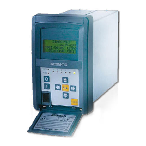
- Page 11 (start-trip). • The event recorder (SER) runs continuously capturing in circular mode the last three hundred events upon trigger of binary input/output. • Digital fault recorder (DFR) in COMTRADE format (oscillography). Photo GENERAL NV10P - Manual - 01 - 2015...
- Page 12 Air discharge 8 kV Reference standards EN 60255-22-3 IEC 60255-22-3 EN 61000-4-3 IEC 61000-4-3 Radiated radio-frequency fi elds • 80...1000 MHz AM 80% 10 V/m • 900 MHz Pulse modulated 10 V/m NV10P - Manual - 01 - 2015 TECHNICAL DATA...
- Page 13 Reference voltage 250 V Overvoltage category Certifi cations Reference standards Product standard for measuring relays EN 50263 CE Conformity • EMC Directive 2004/108/EC • Low Voltage Directive 2006/95/CE Type tests IEC 60255-1 TECHNICAL DATA NV10P - Manual - 01 - 2015...
- Page 14 • ON/fail (green) • Start (yellow) • Trip (red) • Freely allocatable (red) Keyboard 8 keys Note 1 = 100 V or = 400 V version must be selected at ordering NV10P - Manual - 01 - 2015 TECHNICAL DATA...
- Page 15 ModBus®RTU IEC 60870-5-103 DNP3 Ethernet 100BaseT • Connection Optical fi ber 1300 nm, ST 100 Base TX, RJ45 • Baud rate 100 Mbps • Protocol ModBus®TCP/IP, IEC 61850 - Level A TECHNICAL DATA NV10P - Manual - 01 - 2015...
- Page 16 Note 4 The mathematical formula for INVERSE curve is: t= (0.75 ∙ t = operating time (in seconds) < = operating time setting (in seconds) U = input voltage U< = threshold setting NV10P - Manual - 01 - 2015 TECHNICAL DATA...
- Page 17 Note 1 The mathematical formula for INVERSE curve is: t= (0.75 ∙ t = operating time (in seconds) < = operating time setting (in seconds) U = input voltage U< = threshold setting TECHNICAL DATA NV10P - Manual - 01 - 2015...
- Page 18 Note 2 The mathematical formula for INVERSE curve is: t = (0.5 ∙ t = operating time (in seconds) > = operating time setting (in seconds) U = input voltage U> = threshold setting NV10P - Manual - 01 - 2015 TECHNICAL DATA...
- Page 19 Note 4 The mathematical formula for INVERSE curve is t= (0.5 ∙ t = operating time (in seconds) > = operating time setting (in seconds) = residual input voltage (direct or calculated) > = threshold setting TECHNICAL DATA NV10P - Manual - 01 - 2015...
- Page 20 Note 1 The mathematical formula for INVERSE curve is t= (0.5 ∙ t = operating time (in seconds) > = operating time setting (in seconds) > = residual input voltage (calculated), = threshold setting NV10P - Manual - 01 - 2015 TECHNICAL DATA...
- Page 21 (step 0.001 f f>> Operating time (t >> 0.05...100.00 s 0.05...9.99 s (step 0.01 s) 10.0...100.0 s (step 0.1 s) Note 1: 1.5% ± 15 ms with operate time setting = 0.05 s TECHNICAL DATA NV10P - Manual - 01 - 2015...
- Page 22 0.06...10.00 s (step 0.01 s) Dropout ratio 0.95...0.98 Dropout time ≤ 0.05 s Operate time accuracy 5% or ± 10 ms Note 1: 1.5% ± 15 ms with operate time setting = 0.05 s NV10P - Manual - 01 - 2015 TECHNICAL DATA...
- Page 23 Note 1 If the measured frequency is out of the locking range, the system lock on to the rated frequency (50 or 60 Hz) Note 2 For the DFR function a licence is required; call Thytronic for purchasing. Note 3 The measures of temperature are available only when the MPT module on Thybus is enabled (eigth Pt100 inputs) Note 4 Output relay K7...K10 and binary input IN3...IN42 states are available only when the concerning I/O circuits are implemented (MRI and MID16...
- Page 24 Temperature PT3 Temperature PT4 Temperature PT5 Temperature PT6 Temperature PT7 Temperature PT8 Note 1 The measures of temperature are available only when the MPT module on Thybus is enabled (eight Pt100 inputs) NV10P - Manual - 01 - 2015 TECHNICAL DATA...
- Page 25 Uaux Uaux Output contacts Output contacts K1...K6 K1...K6 POWER SUPPLY BOARD POWER SUPPLY BOARD hw.ai hw.ai Printed boards hold the circuit components arranged according to a modular allocation of the main functions. CHARACTERISTICS NV10P - Manual - 01 - 2015...
- Page 26 An eight keys 8 keyboard, • a backlight LCD display, • Eight signalling LEDs, The removable plug allows separation of the MMI module for free access to the CPU board when DIP-switch setting is required. NV10P - Manual - 01 - 2015 CHARACTERISTICS...
- Page 27 The task (process e thread) are the base components. Example are: • Keyboard management • RTC (Real Time Clock) updating • RAM/EEPROM updating • Diagnostic • Input acquisition • Output relay management • • I/O updating • DSP data processing CHARACTERISTICS NV10P - Manual - 01 - 2015...
- Page 28 Xml fi les used for communication. The automatic code generation criteria ensures the quality of the result in terms of the reusability, verifi ability and maintainability of the software life cycle. NV10P - Manual - 01 - 2015 CHARACTERISTICS...
- Page 29 INSTANTANEOUS MEASURES acquisizione-en.ai acquisizione-en.ai ...u Input voltage instantaneous values Residual voltage instantaneous value From the sampled quantities, several measures are computed for protection, monitoring and meter- ing purposes. • Direct • Calculated CHARACTERISTICS NV10P - Manual - 01 - 2015...
- Page 30 L2 - 31 = 31 = L3 - L3 - U12. ai U12. ai Nota 1 La misura delle tre tensioni concatenate è disponibile solo per le versioni con ingressi da sensori NV10P - Manual - 01 - 2015 CHARACTERISTICS...
- Page 31 D i re c t se q uence cy cl i c order D i re c t se q uence cy cl i c order Inverse sequence cy cl i c order Inverse sequence cy cl i c order fasori1.ai fasori1.ai CHARACTERISTICS NV10P - Manual - 01 - 2015...
- Page 32 Event 1 Event 2 Event ... Event 299 FAULT RECORDING (SFR) Fault 0 Fault 1 Fault 2 Fault ... Fault 19 DIGITAL FAULT RECORDER (OSCILLOGRAPHY) Record 1 Record 2 Record 3 Record ... NV10P - Manual - 01 - 2015 CHARACTERISTICS...
- Page 33 Reset CB Monitor (clear CB monitoring data) 52a (CB auxiliary contact) 52b (CB auxiliary contact) Open CB Close CB Remote trip 74VT ext. (74VT from external protection relays f<-f> Control UE>> 27V1 59V2 U< CHARACTERISTICS NV10P - Manual - 01 - 2015...
- Page 34 Note 1 To enable the profi le switching the “Input-selected” parameter must be set inside the “Profi le selection” submenu. If multiple setting groups are not required, Group A is the default selection NV10P - Manual - 01 - 2015 CHARACTERISTICS...
- Page 35 Note 2 The activation of one binary input produces indiscriminately a block of all protective elements programmed for being blocked from Block1 Note 3 The reset of the total counters is practicable by means ThySetter command with Session Level 1 (available with password) CHARACTERISTICS NV10P - Manual - 01 - 2015...
- Page 36 INx t INx t INx t n.o. n.o. Binary input INx Binary input INx UE>> or 27V1 or 59V2 or U< logic block UE>> or 27V1 or 59V2 or U< logic block NV10P - Manual - 01 - 2015 CHARACTERISTICS...
- Page 37 - Energized operating mode, - No-latched , in order that it stays ON for normal conditions and the other way round it goes OFF if any fault is detected and/or the auxiliary supply turns OFF. CHARACTERISTICS NV10P - Manual - 01 - 2015...
- Page 38 BF Trip relays (BF-TR-K) Number of CB trips diagnostic relays (N.Open-K) Circuit breaker opening time diagnostic relays (tbreak-K) Open CB command relays (CBopen-K) Close CB command relays (CBclose-K) Remote tripping relays (RemTrip-K) NV10P - Manual - 01 - 2015 CHARACTERISTICS...
- Page 39 Note 1 The START and the TRIP LED are user assignable to any function; other than starting and tripping information can be assigned to them too, just the same for L1...L5 Note 2 All LEDs are unassigned in the default setting. CHARACTERISTICS NV10P - Manual - 01 - 2015...
- Page 40 BF Trip LEDs (BF-TR-L) Number of CB trips diagnostic LEDs (N.Open-L) Circuit breaker opening time diagnostic LEDs (tbreak-L) Open CB command LEDs (CBopen-L) Close CB command LEDs (CBclose-L) Remote tripping LEDs (RemTrip-L) NV10P - Manual - 01 - 2015 CHARACTERISTICS...
- Page 41 Note 2 The RS485 port is not implemented on the Pro-N devices endowed with Ethernet FX port Note 3 Information about the ModBus map may be fi nd inside the “Remote programming manual” CHARACTERISTICS NV10P - Manual - 01 - 2015...
- Page 42 Phase to ground VTs connection Phase to ground VTs connection Es1-Un.ai Es1-Un.ai The relay nominal voltage may be set to: / √3 · K = 6000 /√3 · 60 = 100 /√3 = 58 V NV10P - Manual - 01 - 2015 CHARACTERISTICS...
- Page 43 The relay nominal voltage may be set to: U = 6000 / 60 = 100 V Example 4 = 400 V = 400 V NV10P NV10P Es4-Un.ai Es4-Un.ai The relay nominal voltage may be set to: U = 400 V CHARACTERISTICS NV10P - Manual - 01 - 2015...
- Page 44 If a VT with primary nominal voltage equal to the grid voltage divided by √3 is connected from star neutral to ground, the following streamlined calculus may be used: = VT secondary nominal voltage [V] NV10P - Manual - 01 - 2015 CHARACTERISTICS...
- Page 45 If the formerly indications concerning the relay nominal voltage U are complied (Phase to ground and phase-to-phase VTS connection diagrams), then the U setting must be adjusted to: = grid nominal voltage [V]]. CHARACTERISTICS NV10P - Manual - 01 - 2015...
- Page 46 Relay residual nominal voltage U = 69 V = 69 V Es-UEnp.ai Es-UEnp.ai The U setting must be adjusted to: U = √3 · U = √3 · 6900 V = 11900 V NV10P - Manual - 01 - 2015 CHARACTERISTICS...
- Page 47 - With RELATIVE setting all measures are related to the nominal value, - With PRIMARY setting all measures are related to the primary value. Note 1 U represents the reference value to which all the adjustments are expressed CHARACTERISTICS NV10P - Manual - 01 - 2015...
- Page 48 DDI OFF->ON DDI OFF->ON (1≡upstream) (1≡upstream) f>> f>> RESET RESET EnTcf>>def EnTcf>>def RESET RESET Operate time reduction after CB closing (eg: f>> element) Operate time reduction after CB closing (eg: f>> element) NV10P - Manual - 01 - 2015 CHARACTERISTICS...
- Page 49 DDI OFF->ON UE>> UE>> (1≡upstream) (1≡upstream) RESET RESET EnTcUE>>def EnTcUE>>def RESET RESET Operate time reduction after CB closing (eg: Operate time reduction after CB closing (eg: element) ) element) ) UE>> UE>> CHARACTERISTICS NV10P - Manual - 01 - 2015...
- Page 50 0 . 2 5 s 0 . 2 5 s 0 . 2 5 s Pt1...8 update Pt1...8 update t-refresh-F26.ai t-refresh-F26.ai Note 1 The 26 menu is available when the MPT module is enabled NV10P - Manual - 01 - 2015 CHARACTERISTICS...
- Page 51 BF Enable (ON≡Enable) Th>xBF Logic diagram for thermal protection with RTD thermometric probes (26) Fun-F26.ai Note 1 The common settings concerning the Breaker failure protection are adjustable inside the Breaker Failure - BF menu. CHARACTERISTICS NV10P - Manual - 01 - 2015...
- Page 52 Device Interface when the DI is open. The threshold disabling is selected by setting ON the U<disbyCB_OPEN, U<<disbyCB_OPEN parameters, inside the Set \ Profi le A(or B) \ Undervoltage-27 \ U< Element (U<< Element) \ Setpoints menu. NV10P - Manual - 01 - 2015 CHARACTERISTICS...
- Page 53 INx t Block1 n.o. Binary input INx Trip U< & U< BF towards BF logic BF Enable (ON≡Enable) U<BF Logic diagram concerning the first threshold (U<) of the undervoltage element - 27 Fun-F27_S1.ai CHARACTERISTICS NV10P - Manual - 01 - 2015...
- Page 54 Note 1 The common settings concerning the Breaker failure protection are adjustable inside the Breaker Failure - BF menu. Note 2 The exhaustive treatment of the logical block (Block 1) function may be found in the “Logic Block” paragraph inside CONTROL AND MONITOR- ING section. NV10P - Manual - 01 - 2015 CHARACTERISTICS...
- Page 55 0.01 0.01 0.25 Note: match of operating and setting time takes place when U/U< = 0.25 Inverse time operating characteristic concerning the first threshold (U<) of the undervoltage element - 27 F_27-Char.ai CHARACTERISTICS NV10P - Manual - 01 - 2015...
- Page 56 ON. The parameter is available inside the Set \ Profi le A(or B) \ Positive sequence undervoltage - 27V1 \ U1< Element \ Setpoints menu. Note 1 The common settings concerning the Breaker failure protection are adjustable inside the Breaker Failure - BF menu. NV10P - Manual - 01 - 2015 CHARACTERISTICS...
- Page 57 Logic diagram concerning the positive sequence undervoltage element - 27V1 Fun-F27V1_S1.ai Fun-F27V1_S1.ai Note 1 The exhaustive treatment of the logical block (Block 1) function may be found in the “Logic Block” paragraph inside CONTROL AND MONITOR- ING section. CHARACTERISTICS NV10P - Manual - 01 - 2015...
- Page 58 Device Interface when the DI is open. The threshold disabling is selected by setting ON the U>disbyCB_OPEN, U>>disbyCB_OPEN parameters, inside the Set \ Profi le A(or B) \ Overvoltage-59 \ U> Element (U>> Element) \ Setpoints menu. NV10P - Manual - 01 - 2015 CHARACTERISTICS...
- Page 59 Logic diagram concerning the first threshold (U>) of the overvoltage element - 59 Fun-F59_S1.ai Fun-F59_S1.ai Note 1 The common settings concerning the Breaker failure protection are adjustable inside the Breaker Failure - BF menu. CHARACTERISTICS NV10P - Manual - 01 - 2015...
- Page 60 Logic diagram concerning the second threshold (U>>) of the overvoltage element - 59 Fun-F59_S2.ai Fun-F59_S2.ai Note 1 The exhaustive treatment of the logical block (Block 1) function may be found in the “Logic Block” paragraph inside CONTROL AND MONITOR- ING section. NV10P - Manual - 01 - 2015 CHARACTERISTICS...
- Page 61 U /U >inv 0.01 Note: match of operating and setting time takes place when U/U> = 1.5 Inverse time operating characteristic concerning the first threshold (U>) of the overvoltage element - 59 F_59-Char.ai CHARACTERISTICS NV10P - Manual - 01 - 2015...
- Page 62 - with initial value 0 and fi nal value 1.1 Uavg> def (1.1x1.1 = 1.21 Un) the pickup time is 498 s - with initial value 0.9 Uavg>def (0.9x1.1 = 0.99 Un) and fi nal value 1.1 Uavg>def (1.1x1.1 = 1.21 Un) the pickup time is 285 s NV10P - Manual - 01 - 2015 CHARACTERISTICS...
- Page 63 Set \ Inputs \ Binary input IN1(x) menus (IN1 or INx matching). All the parameters can be set separately for Profi le A and Profi le B. CHARACTERISTICS NV10P - Manual - 01 - 2015...
- Page 64 Selection of the measuring criteria of the residual voltage (direct measure or calculated measure) is available inside the Set \ Profi le A(or B) \ Residual overvoltage-59N \ Common confi guration menu; The 3Votype59N parameter may be select as UE (direct measure) or UEC (calculated measure). NV10P - Manual - 01 - 2015 CHARACTERISTICS...
- Page 65 Note 1 The operating time must be adjusted to a greater value than the 74VT activation time (internal or binary input) Note 2 The common settings concerning the Breaker failure protection are adjustable inside the Breaker Failure - BF menu. CHARACTERISTICS NV10P - Manual - 01 - 2015...
- Page 66 All the named parameters can be set separately for Profi le A and Profi le B). Note 1 The exhaustive treatment of the logical block (Block 1) function may be found in the “Logic Block” paragraph inside CONTROL AND MONITOR- ING section. NV10P - Manual - 01 - 2015 CHARACTERISTICS...
- Page 67 Binary input INx Trip U >> & towards BF logic >> BF BF Enable (ON≡Enable) UE>>BF Logic diagram concerning the second threshold (UE>>) of the residual overvoltage element - 59N Fun-F59N_S2.ai CHARACTERISTICS NV10P - Manual - 01 - 2015...
- Page 68 Note: match of operating and setting time takes place when = 1.5 or = 1.5 E>inv E>inv Inverse time operating characteristic concerning the first threshold (UE>) of the residual overvoltage element - 59N F_59N-Char.ai NV10P - Manual - 01 - 2015 CHARACTERISTICS...
- Page 69 All the parameters can be set separately for Profi le A and Profi le B. Logical block (Block1) Note 1 The common settings concerning the Breaker failure protection are adjustable inside the Breaker Failure - BF menu. CHARACTERISTICS NV10P - Manual - 01 - 2015...
- Page 70 Logic diagram concerning the threshold (U2>) of the negative sequence overvoltage element - 59V2 Fun-F59V2_S1.ai Fun-F59V2_S1.ai Note 1 The exhaustive treatment of the logical block (Block 1) function may be found in the “Logic Block” paragraph inside CONTROL AND MONITOR- ING section. NV10P - Manual - 01 - 2015 CHARACTERISTICS...
- Page 71 Note 1 For sensors inputs versions the frequency is measured on the phase voltages ( ), while for versions with inductive VTs inputs the frequency is measured on-phase-to-phase voltages ( On the diagrams are the input phase voltages or phase-to-phase according to the corresponding versions CHARACTERISTICS NV10P - Manual - 01 - 2015...
- Page 72 Note 1 The common settings concerning the Breaker failure protection are adjustable inside the Breaker Failure - BF menu. Note 2 The exhaustive treatment of the logical block (Block 1) function may be found in the “Logic Block” paragraph inside CONTROL AND MONITOR- ING section. NV10P - Manual - 01 - 2015 CHARACTERISTICS...
- Page 73 Note 1 For sensors inputs versions the frequency is measured on the phase voltages ( ), while for versions with inductive VTs inputs the frequency is measured on-phase-to-phase voltages ( On the diagrams are the input phase voltages or phase-to-phase according to the corresponding versions CHARACTERISTICS NV10P - Manual - 01 - 2015...
- Page 74 Logic diagram concerning the first threshold (f<) of the underfrequency element - 81U Fun-F81U_S1.ai Note 1 The exhaustive treatment of the logical block (Block 1) function may be found in the “Logic Block” paragraph inside CONTROL AND MONITOR- ING section. NV10P - Manual - 01 - 2015 CHARACTERISTICS...
- Page 75 INx t Block1 n.o. Binary input INx f<<< Trip & f<<< BF towards BF logic BF Enable (ON≡Enable) f<<<BF Logic diagram concerning the third threshold (f<<<) of the underfrequency element - 81U Fun-F81U_S3.ai CHARACTERISTICS NV10P - Manual - 01 - 2015...
- Page 76 INx t Block1 n.o. Binary input INx f<<<< Trip & towards BF logic f<<<< BF BF Enable (ON≡Enable) f<<<<BF Logic diagram concerning the fourth threshold (f<<<<) of the underfrequency element - 81U Fun-F81U_S4.ai NV10P - Manual - 01 - 2015 CHARACTERISTICS...
- Page 77 ON = Fault (Start 59N and/or 27V1 and/or 59V2 element) ON = Fault (Start 59N and/or 27V1 and/or 59V2 element) Operating logic for thresholds activation with voltmetric control Operating logic for thresholds activation with voltmetric control CHARACTERISTICS NV10P - Manual - 01 - 2015...
- Page 78 UE>>def Binary input connected to remote trip external contact Remo t e t r ip Remote trip (Goose IEC61850) Remo t e t r ip Logic diagram concerning the NV10P voltage control NV10P - Manual - 01 - 2015 CHARACTERISTICS...
- Page 79 & Segnale esterno (Presenza Goose IEC61850) Consenso f<-f> f > & r e t e 6 18 5 0 - KO & Logic diagram concerning the 81O-81U threshold enabling (see previous page) CHARACTERISTICS NV10P - Manual - 01 - 2015...
- Page 80 Note 1 For sensors inputs versions the frequency is measured on the phase voltage , while for versions with inductive VTs inputs the frequency is measured on-phase-to-phase voltage On the diagrams are the input phase voltages or phase-to-phase according to the corresponding versions NV10P - Manual - 01 - 2015 CHARACTERISTICS...
- Page 81 All the parameters can be set separately for Profi le A and Profi le B. Note 1 The exhaustive treatment of the logical block (Block 1) function may be found in the “Logic Block” paragraph inside CONTROL AND MONITOR- ING section. CHARACTERISTICS NV10P - Manual - 01 - 2015...
- Page 82 Binary input INx f<< Trip & towards BF logic df>> BF BF Enable (ON≡Enable) df>> BF Logic diagram concerning the second threshold (df>>) of the frequency rate of change element - 81R Fun-F81R_S2.ai NV10P - Manual - 01 - 2015 CHARACTERISTICS...
- Page 83 Binary input INx df>>>> Trip & towards BF logic f<<<< BF BF Enable (ON≡Enable) df>>>>BF Logic diagram concerning the fourth threshold (df>>>>) of the frequency rate of change element - 81R Fun-F81R_S4.ai CHARACTERISTICS NV10P - Manual - 01 - 2015...
- Page 84 (52nd or 52b ) may suffi ce Note 3 The exhaustive treatment of the logic block (Block 1) function may be found in the “Logic Block” paragraph inside CONTROL AND MONITORING section NV10P - Manual - 01 - 2015 CHARACTERISTICS...
- Page 85 BLK1 BF & Logic INx t INx t Block1 n.c. INx t Block1 input (ON≡Block) INx t Block1 n.o. Binary input INx (x=1...8-16) Logic diagram concerning the breaker failure element -BF Fun-BF_Pro-n.ai CHARACTERISTICS NV10P - Manual - 01 - 2015...
- Page 86 Note 1 In the following treatment, the logical block is defi ned as “Logical block” or “Block1” Note 2 The Block 1 signal forces a timer reset NV10P - Manual - 01 - 2015 CHARACTERISTICS...
- Page 87 81R element df>>BLK1 81R element df>>>BLK1 81R element df>>>>BLK1 81R element 74TCSBLK1 74TCS element BFLK1 BF element Block1 info Block1 (internal state) Logic diagram concerning the logic block element -Block1 Block1_L.ai CHARACTERISTICS NV10P - Manual - 01 - 2015...
- Page 88 Phase-to-phase voltage measurement input with direct connection in the LV side (UR = 400 V versions) with 59N detection and processing by means of the device away from the NV10P relay and transmission of 59N start via a digital signal connected to IN1 input of NV10P...
- Page 89 VIN1 and remote trip connected to the VIN2 virtual input of the S2 protection relay. Links (virtual pilot wires) After defi ning the input and output circuits the virtual links must be created. A unique IP address for each relay must be assigned CHARACTERISTICS NV10P - Manual - 01 - 2015...
- Page 90 NV10P Trip - DI-B Trip - DI-B DI-B ≅ DI-A and DI-B Block diagram for the simultaneous opening of two interface Circuit Breaker ( ) made by one or both NV10P relays NV10P - Manual - 01 - 2015 CHARACTERISTICS...
- Page 91 S2, S3 and S4 outputs The output VOUT2 must be set to carry out the logical OR for the opening command of all the circuit breaker interfaces (simultaneous control of all the CBs function from each NV10P): • Trip, used in the example as a trip signal of the protection functions of S1 in order to control the...
- Page 92 RemTrip-K INx t INx t n.o. RemTrip-L Binary input INx Remote trip Remote trip (ON≡Remote trip) towards BF logic Remote trip BF & RemTr B F Remote tripping logic diagram Fun-Remote-trip.ai NV10P - Manual - 01 - 2015 CHARACTERISTICS...
- Page 93 With 24 samples for periods the sampling rate is adjusted from 480 Hz with f = 20 Hz to 1.512 kHz with f= 63 Hz. For a frequency step change the tracking response time is 5 Hz/s for NV10P. The frequency measure is based on the largest voltage input.
- Page 94 (Block 1) function may be found in the “Logic Block” paragraph inside CONTROL AND MONITORING section Note 2 Following assumption are considered for the framework: Logic: ON, Timers t and t reset to zero OFF: TRIP contact of the protection: DE-energized, No latched NV10P - Manual - 01 - 2015 CHARACTERISTICS...
- Page 95 Outputs are reset to zero after 6 s from the TRIP contact open. Note 1 The trip contact (TRIP) of the protection relays must be set with automatic reset (No-latched operating mode). CHARACTERISTICS NV10P - Manual - 01 - 2015...
- Page 96 ) / 2 = (103.7 + 30425) / 2 = 15264 Ω ~ 15 k Ω (Power dissipated by the R resistor) = U /R = 110 / 15000 = 0.8 W NV10P - Manual - 01 - 2015 CHARACTERISTICS...
- Page 97 (tbreak>) is exceeded, an output relay and/or LED can be activated. The four criteria can be contemporaneously or separately set. All the named parameters are available inside the Set\Circuit Breaker supervision\CB Diagnostic menu. CHARACTERISTICS NV10P - Manual - 01 - 2015...
- Page 98 From CB position Opening transition ≥ CB Diagnostic - Number of trips Mode-tOpen State tbreak Ktrig-break break tbreak-K & tbreak-L ≥ From CB position Opening transition CB Diagnostic - CB operating time Fun-CB-diagnostic.ai NV10P - Manual - 01 - 2015 CHARACTERISTICS...
- Page 99 Selection of setting profi les • Remote trip • Include I / O in the programmable logic (PLC) • etc. .. Note 1 For a detailed description please refer to the application notes CHARACTERISTICS NV10P - Manual - 01 - 2015...
- Page 100 Note 1 The 26 menu is available when the MPT module is enabled Nota 2 The output relay K7...K10 and binary input IN3...IN42 states is meaningful when the I/O circuits are present (MRI and MID16 modules) NV10P - Manual - 01 - 2015 CHARACTERISTICS...
- Page 101 All partial counters can be cleared by means a single command; for this purpose the Reset partial counters command must be issued (Commands \ Reset submenu). Not 1 Available for sensor input versions MEASURES, LOGIC STATES AND COUNTERS NV10P - Manual - 01 - 2015...
- Page 102 Recording is triggered by one or more causes (up to 8 simultaneous): • Activation (OFF-ON transition) of any relay programmed for trip of protection or control element External trigger (binary input programmed as Fault trigger) • NV10P - Manual - 01 - 2015 MEASURES, LOGIC STATES AND COUNTERS...
- Page 103 Note 5 Counter is updated at any new record; it may be cleared by means ThySetter Note 3 Data are stored into non volatile memory FLASH, they are preserved also when power goes down MEASURES, LOGIC STATES AND COUNTERS NV10P - Manual - 01 - 2015...
- Page 104 Sampled data: • Analog measures: • Digital channels: K1, K2, K3, K4, K5, K6, IN1, IN2 up to 150 records can be stored if f = 60 Hz NV10P - Manual - 01 - 2015 MEASURES, LOGIC STATES AND COUNTERS...
- Page 105 N.4 holes ø 3,5 N.4 holes ø 3,5 Flush-mount.ai Flush-mount.ai Flush mounting Flush mounting NOTE NOTE Separation of fixed and removable parts is NOT required Separation of fixed and removable parts is NOT required INSTALLATION NV10P - Manual - 01 - 2015...
- Page 106 START START TRIP TRIP Projecting mounting Projecting mounting Projecting.ai Projecting.ai NV10P - Manual - 01 - 2015 INSTALLATION...
- Page 107 N.4 holes ø 4,5 N.4 holes ø 4,5 Separate operator panel Separate operator panel Separate-mount.ai Separate-mount.ai A standard direct shielded cable with RJ45 connectors must be used for connections. Separate operator panel Separate-mount1.ai INSTALLATION NV10P - Manual - 01 - 2015...
- Page 108 Rack mounting Rack mounting Rack-mount.ai Rack-mount.ai To allow opening of the keyboard door a one unit space must be provided when several rack are overlapping mounted. Rack-mount1.ai Rack-mount1.ai Rack mounting Rack mounting NV10P - Manual - 01 - 2015 INSTALLATION...
- Page 109 Devices must be installed by qualified personnel only. CAUTION CAUTION No liability is accepted from Thytronic due to improper use. No liability is accepted from Thytronic due to improper use. A protective ground connection is required, which must be connected to the suitable screw with a separate lead of at least 2.5 mm...
- Page 110 Connessioni per versioni con circuiti d’entrata voltmetrici da sensori A protective ground connection is required, which must be connected to the suitable screw with a separate lead of at least 2.5 mm Ground screw Ground screw Earthing Earthing rear.ai rear.ai NV10P - Manual - 01 - 2015 INSTALLATION...
- Page 111 When no RS232 port is available on Personal Computer, a suitable USB to RS232 converter must be employed. After installation, the same communication port must be selected to defi ne the Thysetter parameters (typically COM4, COM5,...). INSTALLATION NV10P - Manual - 01 - 2015...
- Page 112 Set to OFF the Autonegotiation parameter of NA10 device (Autonegotiation parameter inside • Communication \ Ethernet submenu). For security reasons, a change of the Ethernet communication parameters become active only after an hw reset. NV10P - Manual - 01 - 2015 INSTALLATION...
- Page 113 F2-F3 terminals. Termination resistors allow adjusting the impedance of the line, reducing the infl uence of the induc- tive components of the same, which might compromise good communication. INSTALLATION NV10P - Manual - 01 - 2015...
- Page 114 MODULO INGRESSI REMOTI MID-16 MID-16 IN12 IN12 IN13 IN13 1 2 3 4 5 6 7 8 9 1 2 3 4 5 6 7 8 9 IN14 IN14 IN15 IN15 IN16 IN16 NV10P - Manual - 01 - 2015 INSTALLATION...
- Page 115 One MRI module, two MID16 modules, one MPT module, one MCI module and one MMI module (separate operator panel) can be connect at the same time to the Thybus port (maximum expansion). INSTALLATION NV10P - Manual - 01 - 2015...
- Page 116 The auxiliary voltage in the panel falls within the operative range of Pro_N relays. • The relay rated voltage (100 V or 400 V) corresponds to the Pro_N input voltages. • All wirings are correct. • All screws are tightly screwed. NV10P - Manual - 01 - 2015 INSTALLATION...
- Page 117 The ThySetter sw is a “browser” of data (setting, measure, etc..); it implements an engine that is afford to rebuild the menu set up and the relationships to data concerning all Thytronic protective relays by means of XML fi les.
- Page 118 “PARTIAL COUNTERS >>” “TOTAL COUNTERS >>” “SELF-TEST >>” “FAULT RECORDING >>” “EVENTS RECORDING >>” Note 1 Setting changes are enabled when the La mEnabling setting by MMI parameter is set NV10P - Manual - 01 - 2015 SETTING AND COMMISSIONING...
- Page 119 Press the (Enter) button for a few seconds; new message appears: “Confi rm settings?” • Answer to the message ENTER: YES to confi rm changes or RESET: NO to abort. SETTING AND COMMISSIONING NV10P - Manual - 01 - 2015...
- Page 120 The committed output relays must be enabled inside the Circuit Breaker supervision \ LEDs-relays allocation menu. Note 1 Instantly all the relays are switched in rest state, including relays programmed as “normally energized” NV10P - Manual - 01 - 2015 SETTING AND COMMISSIONING...
- Page 121 - OFF = keyboard enabled only for reading - By password = keyboard enabled for reading and setting by means of password - ON = keyboard enabled for reading and setting without password SETTING AND COMMISSIONING NV10P - Manual - 01 - 2015...
- Page 122 The device serial number should be set to avoid IP address conflicts for devices connected to the Ethernet network. Ethernet network. Following the Set default settings command the password is reset to 0000. NV10P - Manual - 01 - 2015 SETTING AND COMMISSIONING...
- Page 123 K1 relay K1 coil K2 relay K2 coil K3 relay K3 coil RELAYS K4 relay K4 coil K5 relay K5 coil PROCEED READ MENU’ K6 relay K6 coil NV10P_menu1.ai SETTING AND COMMISSIONING NV10P - Manual - 01 - 2015...
- Page 124 Fault 299 Date: Outputs K1-K6 None Time: Fault cause info 0 Event0 (last): ..: IN1 on Eventxx: ..: Date Settings EVENTS RECORDING Time Relay OUT: Date Time PROCEED SET MENU’ NV10P_menu2.ai NV10P - Manual - 01 - 2015 SETTING AND COMMISSIONING...
- Page 125 Relays UE>> U2>BF UE>>ST-K U2>disbyCB_OPEN OFF UE>>TR-K Relays U2> LEDs UE>> U2>ST-K UE>>ST-L U2>TR-K UE>>TR-L LEDs U2> 59V2 U2> Element U2>ST-L U2>TR-L PROCEED SET MENU’ PROCEED PROFILE A MENU’ NV10P_menuset1.ai SETTING AND COMMISSIONING NV10P - Manual - 01 - 2015...
- Page 126 Test state: NTP Synch. Stop test? >> Start test? >> Test K1 >> TEST Test K2 >> Test K3 >> Test K4 >> Test K5 >> Test K6 >> NV10P_menuset2.ai NV10P - Manual - 01 - 2015 SETTING AND COMMISSIONING...
- Page 127 IN14...IN29 with one MID16 module IN30...IN45 with two MID16 modules Output relays K1...K6 on board K7...K10 with MRI module LEDs: ON, START, TRIP, L1...L5 on board L6...L10 with MRI module SETTING AND COMMISSIONING NV10P - Manual - 01 - 2015...
- Page 128 A P P E N D I X A P P E N D I X APPENDIX A1 - I/O Diagram NV10P ≅ NV10P-I-O.ai Measurement of input voltages by means of inductive VTs NV10P - Manual - 01 - 2015 APPENDIX...
- Page 129 NV10P ≅ Misura delle tensioni d’entrata mediante sensori APPENDIX NV10P - Manual - 01 - 2015...
- Page 130 OUTPUT INPUT MID8 MODULO 4 RELE’ + 8 INGRESSI DIGITALI MODULO INGRESSI REMOTI 4 RELAYS + 8 BINARY INPUTS MODULE 1 2 3 4 5 6 7 8 9 FRONT PANEL Interfaces.ai NV10P - Manual - 01 - 2015 APPENDIX...
- Page 131 APPENDIX A3 - Protective functions NV10P inductive VTs inputs 74TCS 59Uavg 27V1 59V2 Electronic sensor inputs 59Uavg Σ 59V2 27V1 APPENDIX NV10P - Manual - 01 - 2015...
- Page 132 All diagram must be considered just as example; they cannot be comprehensive for real applications. For all diagrams the output contacts are shown in de-energized state for standard reference. NV10P 74TCS 27V1 59V2 59Uavg (*) ANTIFERRORESONANZA NV10P-sch2.ai Voltage inputs - phase-to-earth VTs star connections NV10P - Manual - 01 - 2015 APPENDIX...
- Page 133 NV10P 74TCS 27V1 59V2 59Uavg (*) ANTIFERRORESONANZA Voltage inputs - delta connections VTs NV10P-sch4.ai APPENDIX NV10P - Manual - 01 - 2015...
- Page 134 NV10P 74TCS 27V1 59V2 59Uavg (*) ANTIFERRORESONANZA Voltage inputs - “V” connections VTs NV10P-sch7.ai NV10P - Manual - 01 - 2015 APPENDIX...
- Page 135 27V1 59V2 59Uavg Voltage inputs - direct connection to a low voltage network with phase to phase measure (U = 400 V versions) Residual voltage by means of open delta VTs NV10P-sch5.ai APPENDIX NV10P - Manual - 01 - 2015...
- Page 136 BF (K2) NV10P 59Uavg Σ 59V2 27V1 Phase-ground voltage measurement by means of V-Sensor NV10P - Manual - 01 - 2015 APPENDIX...
- Page 137 SEPARATE PROJECTING MOUNTING PROJECTING MOUNTING (Separate operator panel) (Stand alone) OPERATOR PANEL RACK MOUNTING FLUSH MOUNTING CUTOUT 482.6 102.5 ±0.3 START START START START TRIP TRIP TRIP TRIP N.4 holes ø 3.5 APPENDIX NV10P - Manual - 01 - 2015...
- Page 138 To Pro-N protection relay To voltage-indicator lamps RJ45 Connect to ground L10085 if not used Max 50 m Ø53.0 Remove the relay auxiliary supply before connecting or disconnecting the connectors of the sensors NV10P - Manual - 01 - 2015 APPENDIX...
- Page 139 To Pro-N protection relay 3.5 m L10085 Max 50 m Ø 110 Remove the relay auxiliary supply before connecting or disconnecting the connectors of the sensors Fixing hole Fixing hole busbar M12 busbar M12 APPENDIX NV10P - Manual - 01 - 2015...
- Page 140 Reset CB Monitor | 52a | 52b | Open CB | Close CB | Remote trip | 74VT ext. | f<-f> Control | UE>> | 27V1 | 59V2 | U< IN2 matching (B) none Binary input IN3 Logic Active-ON | Active-OFF NV10P - Manual - 01 - 2015 APPENDIX...
- Page 141 Reset CB Monitor | 52a | 52b | Open CB | Close CB | Remote trip | 74VT ext. | f<-f> Control | UE>> | 27V1 | 59V2 | U< IN6 matching (B) none Binary input IN7 APPENDIX NV10P - Manual - 01 - 2015...
- Page 142 IN10 matching (A) Reset CB Monitor | 52a | 52b | Open CB | Close CB | Remote trip | 74VT ext. | f<-f> Control | UE>> | 27V1 | 59V2 | U< NV10P - Manual - 01 - 2015 APPENDIX...
- Page 143 Active-ON | Active-OFF IN14 tON 0.00 ... 9.99 step = 0.01 Value 10.0 ... 100.0 step = 0.1 IN14 tOFF 0.00 ... 9.99 step = 0.01 Value 10.0 ... 100.0 step = 0.1 APPENDIX NV10P - Manual - 01 - 2015...
- Page 144 UE>> | 27V1 | 59V2 | U< IN17 matching (B) none Binary input IN18 IN18 Logic Active-ON | Active-OFF IN18 tON 0.00 ... 9.99 step = 0.01 Value 10.0 ... 100.0 step = 0.1 IN18 tOFF NV10P - Manual - 01 - 2015 APPENDIX...
- Page 145 CB | Remote trip | 74VT ext. | f<-f> Control | UE>> | 27V1 | 59V2 | U< IN21 matching (B) none Binary input IN22 IN22 Logic Active-ON | Active-OFF IN22 tON APPENDIX NV10P - Manual - 01 - 2015...
- Page 146 Reset CB Monitor | 52a | 52b | Open CB | Close CB | Remote trip | 74VT ext. | f<-f> Control | UE>> | 27V1 | 59V2 | U< IN25 matching (B) none Binary input IN26 IN26 NV10P - Manual - 01 - 2015 APPENDIX...
- Page 147 Reset CB Monitor | 52a | 52b | Open CB | Close CB | Remote trip | 74VT ext. | f<-f> Control | UE>> | 27V1 | 59V2 | U< IN29 matching (B) none APPENDIX NV10P - Manual - 01 - 2015...
- Page 148 Active-ON | Active-OFF IN33 tON 0.00 ... 9.99 step = 0.01 Value 10.0 ... 100.0 step = 0.1 IN33 tOFF 0.00 ... 9.99 step = 0.01 Value 10.0 ... 100.0 step = 0.1 NV10P - Manual - 01 - 2015 APPENDIX...
- Page 149 UE>> | 27V1 | 59V2 | U< IN36 matching (B) none Binary input IN37 IN37 Logic Active-ON | Active-OFF IN37 tON 0.00 ... 9.99 step = 0.01 Value 10.0 ... 100.0 step = 0.1 IN37 tOFF APPENDIX NV10P - Manual - 01 - 2015...
- Page 150 CB | Remote trip | 74VT ext. | f<-f> Control | UE>> | 27V1 | 59V2 | U< IN40 matching (B) none Binary input IN41 IN41 Logic Active-ON | Active-OFF IN41 tON NV10P - Manual - 01 - 2015 APPENDIX...
- Page 151 No-latched | Pulse | Latched Minimum pulse width 0 ... 500 step = 5 Logic De-energized | Energized Operation MODE No-latched | Pulse | Latched Minimum pulse width 0 ... 500 step = 5 APPENDIX NV10P - Manual - 01 - 2015...
- Page 152 0-5 mA | 0-20 mA | 4-20 mA Loop 2 Output type Loop2-Type Unipolar | Bipolar Loop 2 Nominal multiplier Loop2-M 0.01 ... 100.00 step = 0.01 Loop 2 Terminals polarity Loop2-Polarity Normal | Reverse Current loop 3 NV10P - Manual - 01 - 2015 APPENDIX...
- Page 153 | L9 | L10 Th>2 Trip Th>2 Enable Th>2 Enable OFF | ON 26 PT2 Trip threshold Th>2 0 ... 200 step = 1 Th>2 Operating time Value 0 ... 100 step = 1 APPENDIX NV10P - Manual - 01 - 2015...
- Page 154 | L9 | L10 Th>5 Trip Th>5 Enable Th>5 Enable OFF | ON 26 PT5 Trip threshold Th>5 0 ... 200 step = 1 Th>5 Operating time Value 0 ... 100 step = 1 NV10P - Manual - 01 - 2015 APPENDIX...
- Page 155 | L9 | L10 Th>8 Trip Th>8 Enable Th>8 Enable OFF | ON 26 PT8 Trip threshold Th>8 0 ... 200 step = 1 Th>8 Operating time Value 0 ... 100 step = 1 APPENDIX NV10P - Manual - 01 - 2015...
- Page 156 START | TRIP | L1 | L2 | L3 | L4 | L5 | L6 | L7 | L8 U<< Trip LEDs U<<TR-L | L9 | L10 Defi nite time 27 Second threshold defi nite time State OFF | ON Pickup value 0.05 ... 1.10 step = 0.01 NV10P - Manual - 01 - 2015 APPENDIX...
- Page 157 59 First threshold inverse time State OFF | ON Pickup value 0.50 ... 1.50 step = 0.01 0.10 ... 9.99 step = 0.01 U>inv Operating time tU>inv 10.0 ... 100.0 step = 0.1 U>> Element Setpoints APPENDIX NV10P - Manual - 01 - 2015...
- Page 158 INVERSE | DEFINITE UE> Reset time delay 0.00 ... 9.99 step = 0.01 Value 10.0 ... 100.0 step = 0.1 UE> Logical block UE>BLK1 OFF | ON UE> Breaker failure UE>BF OFF | ON NV10P - Manual - 01 - 2015 APPENDIX...
- Page 159 1 ... 60 step = 1 Negative sequence overvoltage - 59V2 U2> Element Setpoints U2> Logical block U2>BLK1 OFF | ON U2> Breaker failure U2>BF OFF | ON U2>disbyCB_ OFF | ON U2> Disabling by CB_OPEN OPEN APPENDIX NV10P - Manual - 01 - 2015...
- Page 160 Logical block f>>BLK1 OFF | ON f>> Breaker failure f>>BF OFF | ON f> Disabling by f>> start f>disbyf>> OFF | ON f>>disbyCB_ OFF | ON f>> Disabling by CB_OPEN OPEN NV10P - Manual - 01 - 2015 APPENDIX...
- Page 161 START | TRIP | L1 | L2 | L3 | L4 | L5 | L6 | L7 | L8 f< Control LEDs f<&-L | L9 | L10 f<< Element Setpoints f<< Logical block f<<BLK1 OFF | ON APPENDIX NV10P - Manual - 01 - 2015...
- Page 162 K1 | K2 | K3 | K4 | K5 | K6 | K7 | K8 | K9 | K10 f<<<< Trip relays f<<<<TR-K K1 | K2 | K3 | K4 | K5 | K6 | K7 | K8 | K9 | K10 NV10P - Manual - 01 - 2015 APPENDIX...
- Page 163 State OFF | ON Pickup value Hz/s 0.1 ... 10.0 step = 0.1 df>>def Operating time 0.00 ... 9.99 step = 0.01 Value 10.0 ... 100.0 step = 0.1 df>>> Element Setpoints APPENDIX NV10P - Manual - 01 - 2015...
- Page 164 START | TRIP | L1 | L2 | L3 | L4 | L5 | L6 | L7 | L8 74TCS Trip LEDs 74TCS-TR-L | L9 | L10 Breaker failure - BF BF Enable BF Enable OFF | ON NV10P - Manual - 01 - 2015 APPENDIX...
- Page 165 ThAL3 Operating time Value 0 ... 100 step = 1 ThAL3 Alarm relays ThAL3-K K1 | K2 | K3 | K4 | K5 | K6 | K7 | K8 | K9 | K10 APPENDIX NV10P - Manual - 01 - 2015...
- Page 166 ThAL6 Operating time Value 0 ... 100 step = 1 ThAL6 Alarm relays ThAL6-K K1 | K2 | K3 | K4 | K5 | K6 | K7 | K8 | K9 | K10 NV10P - Manual - 01 - 2015 APPENDIX...
- Page 167 START | TRIP | L1 | L2 | L3 | L4 | L5 | L6 | L7 | L8 PT100 probe diagnostic LEDs PT100Diag-L | L9 | L10 Undervoltage - 27 Common confi guration 27 Operating logic Logic27 OR | AND APPENDIX NV10P - Manual - 01 - 2015...
- Page 168 U1<disbyCB_ OFF | ON U1< Disabling by CB_OPEN OPEN U1< Start relays U1<ST-K K1 | K2 | K3 | K4 | K5 | K6 | K7 | K8 | K9 | K10 NV10P - Manual - 01 - 2015 APPENDIX...
- Page 169 U>>ST-L | L9 | L10 START | TRIP | L1 | L2 | L3 | L4 | L5 | L6 | L7 | L8 U>> Trip LEDs U>>TR-L | L9 | L10 APPENDIX NV10P - Manual - 01 - 2015...
- Page 170 START | TRIP | L1 | L2 | L3 | L4 | L5 | L6 | L7 | L8 UE> Trip LEDs UE>TR-L | L9 | L10 Defi nite time 59N First threshold defi nite time State OFF | ON Pickup value 0.01 ... 0.70 step = 0.01 NV10P - Manual - 01 - 2015 APPENDIX...
- Page 171 U2> Trip LEDs U2>TR-L | L9 | L10 Defi nite time 59V2 First threshold defi nite time State OFF | ON Pickup value 0.01 ... 0.50 step = 0.01 U2>def Operating time APPENDIX NV10P - Manual - 01 - 2015...
- Page 172 Trip LEDs f>>TR-L | L9 | L10 Defi nite time 81O Second threshold defi nite time State OFF | ON Pickup value 1.000 ... 1.200 step = 0.001 f>>def Operating time NV10P - Manual - 01 - 2015 APPENDIX...
- Page 173 | L9 | L10 START | TRIP | L1 | L2 | L3 | L4 | L5 | L6 | L7 | L8 f<< Trip LEDs f<<TR-L | L9 | L10 Defi nite time APPENDIX NV10P - Manual - 01 - 2015...
- Page 174 OFF | ON Pickup value 0.800 ... 1.000 step = 0.001 f<<<<def Operating time 0.05 ... 9.99 step = 0.01 Value 10.0 ... 100.0 step = 0.1 Frequency rate of change - 81R NV10P - Manual - 01 - 2015 APPENDIX...
- Page 175 K1 | K2 | K3 | K4 | K5 | K6 | K7 | K8 | K9 | K10 START | TRIP | L1 | L2 | L3 | L4 | L5 | L6 | L7 | L8 df>>> Start LEDs df>>>ST-L | L9 | L10 APPENDIX NV10P - Manual - 01 - 2015...
- Page 176 | L9 | L10 START | TRIP | L1 | L2 | L3 | L4 | L5 | L6 | L7 | L8 BF Trip LEDs BF-TR-L | L9 | L10 Setpoints NV10P - Manual - 01 - 2015 APPENDIX...
- Page 177 | 80 | 81 | 82 | 83 | 84 | 85 | 86 | 87 | 88 | 89 | 90 | 91 | 92 | 93 | 94 | 95 | 96 | 97 | 98 | 99 APPENDIX NV10P - Manual - 01 - 2015...
- Page 178 60 ... 299 step = 1 300 ... 3600 step = 10 0.0 ... 59.9 step = 0.1 Timer 16 60 ... 299 step = 1 300 ... 3600 step = 10 NV10P - Manual - 01 - 2015 APPENDIX...
- Page 179 K1 | K2 | K3 | K4 | K5 | K6 | K7 | K8 | K9 | K10 CB Diagnostic Number of CB trips mode ModeN.Open OFF | ON Number of CB trips threshold N.Open 0 ... 10000 step = 1 CB operating time mode Mode-tOpen OFF | ON APPENDIX NV10P - Manual - 01 - 2015...
- Page 180 IN33 | IN34 | IN35 | IN36 | IN37 | IN38 | IN39 | Input Mask2 IN40 | IN41 | IN42 VOUT2 Type Start | Trip | Plc | Input Start UE>> | 27V1 | 59V2 | U< | TEST_START NV10P - Manual - 01 - 2015 APPENDIX...
- Page 181 | IN17 | IN18 | IN19 | IN20 | IN21 | IN22 | IN23 | IN24 | IN25 | IN26 | IN27 | IN28 | IN29 | IN30 | IN31 | IN32 APPENDIX NV10P - Manual - 01 - 2015...
- Page 182 Trip TR | BF-TR | TEST_TRIP | U1<TR | Uavg>TR | U2>TR | f>TR | f>>TR | f<TR | f<<TR | f<<<TR | f<<<<TR | df>TR | df>>TR | df>>>TR | df>>>>TR NV10P - Manual - 01 - 2015 APPENDIX...
- Page 183 IN33 | IN34 | IN35 | IN36 | IN37 | IN38 | IN39 | Input Mask2 IN40 | IN41 | IN42 VOUT13 Type Start | Trip | Plc | Input Start UE>> | 27V1 | 59V2 | U< | TEST_START APPENDIX NV10P - Manual - 01 - 2015...
- Page 184 | IN17 | IN18 | IN19 | IN20 | IN21 | IN22 | IN23 | IN24 | IN25 | IN26 | IN27 | IN28 | IN29 | IN30 | IN31 | IN32 NV10P - Manual - 01 - 2015 APPENDIX...
- Page 185 Reset CB Monitor | 52a | 52b | Open CB | Close CB | Remote trip | 74VT ext. | f<-f> Control | UE>> | 27V1 | 59V2 | U< VIN5-Function (B) none APPENDIX NV10P - Manual - 01 - 2015...
- Page 186 VIN13-Function (A) Reset CB Monitor | 52a | 52b | Open CB | Close CB | Remote trip | 74VT ext. | f<-f> Control | UE>> | 27V1 | 59V2 | U< NV10P - Manual - 01 - 2015 APPENDIX...
- Page 187 CB | Remote trip | 74VT ext. | f<-f> Control | UE>> | 27V1 | 59V2 | U< VIN21-Function (B) none VIN21-K K1 | K2 | K3 | K4 | K5 | K6 | K7 | K8 | K9 | K10 APPENDIX NV10P - Manual - 01 - 2015...
- Page 188 CB | Remote trip | 74VT ext. | f<-f> Control | UE>> | 27V1 | 59V2 | U< VIN29-Function (B) none VIN29-K K1 | K2 | K3 | K4 | K5 | K6 | K7 | K8 | K9 | K10 NV10P - Manual - 01 - 2015 APPENDIX...
- Page 189 Trigger from inputs IN33-IN42 IN40 | IN41 | IN42 80% Buffer alarm OFF | ON Set sample channels On | Off On | Off On | Off On | Off Set analog channels APPENDIX NV10P - Manual - 01 - 2015...
- Page 190 | IN24 | IN25 | IN26 | IN27 | IN28 | IN29 | IN30 | IN31 | IN32 | IN33 | IN34 | IN35 | IN36 | IN37 | IN38 | IN39 | IN40 | IN41 | IN42 | Off NV10P - Manual - 01 - 2015 APPENDIX...
- Page 191 | IN24 | IN25 | IN26 | IN27 | IN28 | IN29 | IN30 | IN31 | IN32 | IN33 | IN34 | IN35 | IN36 | IN37 | IN38 | IN39 | IN40 | IN41 | IN42 | Off APPENDIX NV10P - Manual - 01 - 2015...
- Page 192 VOUT1 | VOUT2 | VOUT3 | VOUT4 | VOUT5 | VOUT6 | VOUT7 | VOUT8 | VOUT9 | VOUT10 Pair_2 Local Vout | VOUT11 | VOUT12 | VOUT13 | VOUT14 | VOUT15 | VOUT16 | NONE NV10P - Manual - 01 - 2015 APPENDIX...
- Page 193 VOUT1 | VOUT2 | VOUT3 | VOUT4 | VOUT5 | VOUT6 | VOUT7 | VOUT8 | VOUT9 | VOUT10 Pair_8 Local Vout | VOUT11 | VOUT12 | VOUT13 | VOUT14 | VOUT15 | VOUT16 | NONE APPENDIX NV10P - Manual - 01 - 2015...
- Page 194 VOUT1 | VOUT2 | VOUT3 | VOUT4 | VOUT5 | VOUT6 | VOUT7 | VOUT8 | VOUT9 | VOUT10 Pair_14 Local Vout | VOUT11 | VOUT12 | VOUT13 | VOUT14 | VOUT15 | VOUT16 | NONE NV10P - Manual - 01 - 2015 APPENDIX...
- Page 195 VIN14 | VIN15 | VIN16 | VIN17 | VIN18 | VIN19 Pair_3 Remote Vin | VIN20 | VIN21 | VIN22 | VIN23 | VIN24 | VIN25 | VIN26 | VIN27 | VIN28 | VIN29 | VIN30 | VIN31 | VIN32 | NONE APPENDIX NV10P - Manual - 01 - 2015...
- Page 196 VIN14 | VIN15 | VIN16 | VIN17 | VIN18 | VIN19 Pair_9 Remote Vin | VIN20 | VIN21 | VIN22 | VIN23 | VIN24 | VIN25 | VIN26 | VIN27 | VIN28 | VIN29 | VIN30 | VIN31 | VIN32 | NONE NV10P - Manual - 01 - 2015 APPENDIX...
- Page 197 VIN14 | VIN15 | VIN16 | VIN17 | VIN18 | VIN19 Pair_15 Remote Vin | VIN20 | VIN21 | VIN22 | VIN23 | VIN24 | VIN25 | VIN26 | VIN27 | VIN28 | VIN29 | VIN30 | VIN31 | VIN32 | NONE APPENDIX NV10P - Manual - 01 - 2015...
- Page 198 VOUT1 | VOUT2 | VOUT3 | VOUT4 | VOUT5 | VOUT6 | VOUT7 | VOUT8 | VOUT9 | VOUT10 Pair_5 Local Vout | VOUT11 | VOUT12 | VOUT13 | VOUT14 | VOUT15 | VOUT16 | NONE NV10P - Manual - 01 - 2015 APPENDIX...
- Page 199 VOUT1 | VOUT2 | VOUT3 | VOUT4 | VOUT5 | VOUT6 | VOUT7 | VOUT8 | VOUT9 | VOUT10 Pair_11 Local Vout | VOUT11 | VOUT12 | VOUT13 | VOUT14 | VOUT15 | VOUT16 | NONE APPENDIX NV10P - Manual - 01 - 2015...
- Page 200 VIN25 | VIN26 | VIN27 | VIN28 | VIN29 | VIN30 | VIN31 | VIN32 | NONE Enable OFF | ON Address LEDs None | START | TRIP | L1 | L2 | L3 | L4 | L5 CONN4 VOUT/IN PAIR NV10P - Manual - 01 - 2015 APPENDIX...
- Page 201 VIN14 | VIN15 | VIN16 | VIN17 | VIN18 | VIN19 Pair_6 Remote Vin | VIN20 | VIN21 | VIN22 | VIN23 | VIN24 | VIN25 | VIN26 | VIN27 | VIN28 | VIN29 | VIN30 | VIN31 | VIN32 | NONE APPENDIX NV10P - Manual - 01 - 2015...
- Page 202 VIN14 | VIN15 | VIN16 | VIN17 | VIN18 | VIN19 Pair_12 Remote Vin | VIN20 | VIN21 | VIN22 | VIN23 | VIN24 | VIN25 | VIN26 | VIN27 | VIN28 | VIN29 | VIN30 | VIN31 | VIN32 | NONE NV10P - Manual - 01 - 2015 APPENDIX...
- Page 203 VOUT1 | VOUT2 | VOUT3 | VOUT4 | VOUT5 | VOUT6 | VOUT7 | VOUT8 | VOUT9 | VOUT10 Pair_2 Local Vout | VOUT11 | VOUT12 | VOUT13 | VOUT14 | VOUT15 | VOUT16 | NONE APPENDIX NV10P - Manual - 01 - 2015...
- Page 204 VOUT1 | VOUT2 | VOUT3 | VOUT4 | VOUT5 | VOUT6 | VOUT7 | VOUT8 | VOUT9 | VOUT10 Pair_8 Local Vout | VOUT11 | VOUT12 | VOUT13 | VOUT14 | VOUT15 | VOUT16 | NONE NV10P - Manual - 01 - 2015 APPENDIX...
- Page 205 VOUT1 | VOUT2 | VOUT3 | VOUT4 | VOUT5 | VOUT6 | VOUT7 | VOUT8 | VOUT9 | VOUT10 Pair_14 Local Vout | VOUT11 | VOUT12 | VOUT13 | VOUT14 | VOUT15 | VOUT16 | NONE APPENDIX NV10P - Manual - 01 - 2015...
- Page 206 VIN14 | VIN15 | VIN16 | VIN17 | VIN18 | VIN19 Pair_3 Remote Vin | VIN20 | VIN21 | VIN22 | VIN23 | VIN24 | VIN25 | VIN26 | VIN27 | VIN28 | VIN29 | VIN30 | VIN31 | VIN32 | NONE NV10P - Manual - 01 - 2015 APPENDIX...
- Page 207 VIN14 | VIN15 | VIN16 | VIN17 | VIN18 | VIN19 Pair_9 Remote Vin | VIN20 | VIN21 | VIN22 | VIN23 | VIN24 | VIN25 | VIN26 | VIN27 | VIN28 | VIN29 | VIN30 | VIN31 | VIN32 | NONE APPENDIX NV10P - Manual - 01 - 2015...
- Page 208 VIN14 | VIN15 | VIN16 | VIN17 | VIN18 | VIN19 Pair_15 Remote Vin | VIN20 | VIN21 | VIN22 | VIN23 | VIN24 | VIN25 | VIN26 | VIN27 | VIN28 | VIN29 | VIN30 | VIN31 | VIN32 | NONE NV10P - Manual - 01 - 2015 APPENDIX...
- Page 209 VOUT1 | VOUT2 | VOUT3 | VOUT4 | VOUT5 | VOUT6 | VOUT7 | VOUT8 | VOUT9 | VOUT10 Pair_5 Local Vout | VOUT11 | VOUT12 | VOUT13 | VOUT14 | VOUT15 | VOUT16 | NONE APPENDIX NV10P - Manual - 01 - 2015...
- Page 210 VOUT1 | VOUT2 | VOUT3 | VOUT4 | VOUT5 | VOUT6 | VOUT7 | VOUT8 | VOUT9 | VOUT10 Pair_11 Local Vout | VOUT11 | VOUT12 | VOUT13 | VOUT14 | VOUT15 | VOUT16 | NONE NV10P - Manual - 01 - 2015 APPENDIX...
- Page 211 VIN25 | VIN26 | VIN27 | VIN28 | VIN29 | VIN30 | VIN31 | VIN32 | NONE Enable OFF | ON Address LEDs None | START | TRIP | L1 | L2 | L3 | L4 | L5 CONN8 VOUT/IN PAIR APPENDIX NV10P - Manual - 01 - 2015...
- Page 212 VIN14 | VIN15 | VIN16 | VIN17 | VIN18 | VIN19 Pair_6 Remote Vin | VIN20 | VIN21 | VIN22 | VIN23 | VIN24 | VIN25 | VIN26 | VIN27 | VIN28 | VIN29 | VIN30 | VIN31 | VIN32 | NONE NV10P - Manual - 01 - 2015 APPENDIX...
- Page 213 VIN14 | VIN15 | VIN16 | VIN17 | VIN18 | VIN19 Pair_12 Remote Vin | VIN20 | VIN21 | VIN22 | VIN23 | VIN24 | VIN25 | VIN26 | VIN27 | VIN28 | VIN29 | VIN30 | VIN31 | VIN32 | NONE APPENDIX NV10P - Manual - 01 - 2015...
- Page 214 Device 9 0 ... 999999 step = 1 Device 10 0 ... 999999 step = 1 Device 11 0 ... 999999 step = 1 Device 12 0 ... 999999 step = 1 NV10P - Manual - 01 - 2015 APPENDIX...
- Page 215 VOUT1 | VOUT2 | VOUT3 | VOUT4 | VOUT5 | VOUT6 | VOUT7 | VOUT8 | VOUT9 | VOUT10 Pair_5 Local Vout | VOUT11 | VOUT12 | VOUT13 | VOUT14 | VOUT15 | VOUT16 | NONE APPENDIX NV10P - Manual - 01 - 2015...
- Page 216 VOUT1 | VOUT2 | VOUT3 | VOUT4 | VOUT5 | VOUT6 | VOUT7 | VOUT8 | VOUT9 | VOUT10 Pair_11 Local Vout | VOUT11 | VOUT12 | VOUT13 | VOUT14 | VOUT15 | VOUT16 | NONE NV10P - Manual - 01 - 2015 APPENDIX...
- Page 217 VIN25 | VIN26 | VIN27 | VIN28 | VIN29 | VIN30 | VIN31 | VIN32 | NONE Enable OFF | ON Address LEDs None | START | TRIP | L1 | L2 | L3 | L4 | L5 CONN2 VOUT/IN PAIR APPENDIX NV10P - Manual - 01 - 2015...
- Page 218 VIN14 | VIN15 | VIN16 | VIN17 | VIN18 | VIN19 Pair_6 Remote Vin | VIN20 | VIN21 | VIN22 | VIN23 | VIN24 | VIN25 | VIN26 | VIN27 | VIN28 | VIN29 | VIN30 | VIN31 | VIN32 | NONE NV10P - Manual - 01 - 2015 APPENDIX...
- Page 219 VIN14 | VIN15 | VIN16 | VIN17 | VIN18 | VIN19 Pair_12 Remote Vin | VIN20 | VIN21 | VIN22 | VIN23 | VIN24 | VIN25 | VIN26 | VIN27 | VIN28 | VIN29 | VIN30 | VIN31 | VIN32 | NONE APPENDIX NV10P - Manual - 01 - 2015...
- Page 220 VOUT1 | VOUT2 | VOUT3 | VOUT4 | VOUT5 | VOUT6 | VOUT7 | VOUT8 | VOUT9 | VOUT10 Pair_2 Local Vout | VOUT11 | VOUT12 | VOUT13 | VOUT14 | VOUT15 | VOUT16 | NONE NV10P - Manual - 01 - 2015 APPENDIX...
- Page 221 VOUT1 | VOUT2 | VOUT3 | VOUT4 | VOUT5 | VOUT6 | VOUT7 | VOUT8 | VOUT9 | VOUT10 Pair_8 Local Vout | VOUT11 | VOUT12 | VOUT13 | VOUT14 | VOUT15 | VOUT16 | NONE APPENDIX NV10P - Manual - 01 - 2015...
- Page 222 VOUT1 | VOUT2 | VOUT3 | VOUT4 | VOUT5 | VOUT6 | VOUT7 | VOUT8 | VOUT9 | VOUT10 Pair_14 Local Vout | VOUT11 | VOUT12 | VOUT13 | VOUT14 | VOUT15 | VOUT16 | NONE NV10P - Manual - 01 - 2015 APPENDIX...
- Page 223 VIN14 | VIN15 | VIN16 | VIN17 | VIN18 | VIN19 Pair_3 Remote Vin | VIN20 | VIN21 | VIN22 | VIN23 | VIN24 | VIN25 | VIN26 | VIN27 | VIN28 | VIN29 | VIN30 | VIN31 | VIN32 | NONE APPENDIX NV10P - Manual - 01 - 2015...
- Page 224 VIN14 | VIN15 | VIN16 | VIN17 | VIN18 | VIN19 Pair_9 Remote Vin | VIN20 | VIN21 | VIN22 | VIN23 | VIN24 | VIN25 | VIN26 | VIN27 | VIN28 | VIN29 | VIN30 | VIN31 | VIN32 | NONE NV10P - Manual - 01 - 2015 APPENDIX...
- Page 225 VIN14 | VIN15 | VIN16 | VIN17 | VIN18 | VIN19 Pair_15 Remote Vin | VIN20 | VIN21 | VIN22 | VIN23 | VIN24 | VIN25 | VIN26 | VIN27 | VIN28 | VIN29 | VIN30 | VIN31 | VIN32 | NONE APPENDIX NV10P - Manual - 01 - 2015...
- Page 226 VOUT1 | VOUT2 | VOUT3 | VOUT4 | VOUT5 | VOUT6 | VOUT7 | VOUT8 | VOUT9 | VOUT10 Pair_5 Local Vout | VOUT11 | VOUT12 | VOUT13 | VOUT14 | VOUT15 | VOUT16 | NONE NV10P - Manual - 01 - 2015 APPENDIX...
- Page 227 VOUT1 | VOUT2 | VOUT3 | VOUT4 | VOUT5 | VOUT6 | VOUT7 | VOUT8 | VOUT9 | VOUT10 Pair_11 Local Vout | VOUT11 | VOUT12 | VOUT13 | VOUT14 | VOUT15 | VOUT16 | NONE APPENDIX NV10P - Manual - 01 - 2015...
- Page 228 VIN25 | VIN26 | VIN27 | VIN28 | VIN29 | VIN30 | VIN31 | VIN32 | NONE Enable OFF | ON Address LEDs None | START | TRIP | L1 | L2 | L3 | L4 | L5 CONN6 VOUT/IN PAIR NV10P - Manual - 01 - 2015 APPENDIX...
- Page 229 VIN14 | VIN15 | VIN16 | VIN17 | VIN18 | VIN19 Pair_6 Remote Vin | VIN20 | VIN21 | VIN22 | VIN23 | VIN24 | VIN25 | VIN26 | VIN27 | VIN28 | VIN29 | VIN30 | VIN31 | VIN32 | NONE APPENDIX NV10P - Manual - 01 - 2015...
- Page 230 VIN14 | VIN15 | VIN16 | VIN17 | VIN18 | VIN19 Pair_12 Remote Vin | VIN20 | VIN21 | VIN22 | VIN23 | VIN24 | VIN25 | VIN26 | VIN27 | VIN28 | VIN29 | VIN30 | VIN31 | VIN32 | NONE NV10P - Manual - 01 - 2015 APPENDIX...
- Page 231 VOUT1 | VOUT2 | VOUT3 | VOUT4 | VOUT5 | VOUT6 | VOUT7 | VOUT8 | VOUT9 | VOUT10 Pair_2 Local Vout | VOUT11 | VOUT12 | VOUT13 | VOUT14 | VOUT15 | VOUT16 | NONE APPENDIX NV10P - Manual - 01 - 2015...
- Page 232 VOUT1 | VOUT2 | VOUT3 | VOUT4 | VOUT5 | VOUT6 | VOUT7 | VOUT8 | VOUT9 | VOUT10 Pair_8 Local Vout | VOUT11 | VOUT12 | VOUT13 | VOUT14 | VOUT15 | VOUT16 | NONE NV10P - Manual - 01 - 2015 APPENDIX...
- Page 233 VOUT1 | VOUT2 | VOUT3 | VOUT4 | VOUT5 | VOUT6 | VOUT7 | VOUT8 | VOUT9 | VOUT10 Pair_14 Local Vout | VOUT11 | VOUT12 | VOUT13 | VOUT14 | VOUT15 | VOUT16 | NONE APPENDIX NV10P - Manual - 01 - 2015...
- Page 234 VIN14 | VIN15 | VIN16 | VIN17 | VIN18 | VIN19 Pair_3 Remote Vin | VIN20 | VIN21 | VIN22 | VIN23 | VIN24 | VIN25 | VIN26 | VIN27 | VIN28 | VIN29 | VIN30 | VIN31 | VIN32 | NONE NV10P - Manual - 01 - 2015 APPENDIX...
- Page 235 VIN14 | VIN15 | VIN16 | VIN17 | VIN18 | VIN19 Pair_9 Remote Vin | VIN20 | VIN21 | VIN22 | VIN23 | VIN24 | VIN25 | VIN26 | VIN27 | VIN28 | VIN29 | VIN30 | VIN31 | VIN32 | NONE APPENDIX NV10P - Manual - 01 - 2015...
- Page 236 VIN14 | VIN15 | VIN16 | VIN17 | VIN18 | VIN19 Pair_15 Remote Vin | VIN20 | VIN21 | VIN22 | VIN23 | VIN24 | VIN25 | VIN26 | VIN27 | VIN28 | VIN29 | VIN30 | VIN31 | VIN32 | NONE NV10P - Manual - 01 - 2015 APPENDIX...
- Page 237 | VIN31 | VIN32 | NONE Enable OFF | ON Address LEDs None | START | TRIP | L1 | L2 | L3 | L4 | L5 Test Signal Simulator TEST state OFF | ON APPENDIX NV10P - Manual - 01 - 2015...
- Page 238 1.61 NV10-Manual-09-2009 ThySetter 3.5.4 TCS description with R dimensioning, PLL data, connection diagrams 1.51 2.00 NV10-Manual-05-2010 ThySetter 3.5.8 PLL data (different lock rate for NV10B and NV10P) 1.51 2.00 NV10-Manual-05-2010 ThySetter 3.5.8 Corrections on BF logic diagram 1.51 2.00 NV10-Manual-05-2010 ThySetter 3.6.1...
- Page 239 Title EN 60255-1 2011 Electrical relays Part 6: General requirements for measuring relays and protection equipment Year of CE marking: 2006 Signature ..........Name FIORE Ing. GIOACCHINO Title Managing director Date 12-2006 APPENDIX NV10P - Manual - 01 - 2015...
- Page 240 Headquarters: 20139 Milano - Piazza Mistral, 7 - Tel. +39 02 574 957 01 ra - Fax +39 02 574 037 63 Factory: 35127 Padova - Z.I. Sud - Via dell’Artigianato, 48 - Tel. +39 049 894 770 1 ra - Fax +39 049 870 139 0 www.thytronic.it thytronic@thytronic.it...
Need help?
Do you have a question about the NV10P and is the answer not in the manual?
Questions and answers