Table of Contents

Subscribe to Our Youtube Channel
Related Manuals for Thytronic DMC3S


Summary of Contents for Thytronic DMC3S
- Page 1 DMC3S MULTIFUNCTIONAL PROTECTION AND CONTROL PANEL FOR PRIMARY SUBSTATIONS MANUAL DV901 MV line DV7203 DV905 Translator DV907 Coupler Power factor DV910 correction DV917 HV line Ethernet locale DV922 DMC3S - Manual - 08 - 2021...
-
Page 2: Table Of Contents
Residual emergency overcurrent - 59N(eme) ............................19 Maximum directional current - 67 ................................20 Ground directional overcurrent - 67N ................................22 EAC (Equilibratore Automatico di Carico) [ALB frequency (Automatic Load Balancer)] ..............25 Second harmonic restraint - 2ndh-REST ..............................25 DMC3S - Manual - 08 - 2021... - Page 3 CYBER SECURITY Configuration management ..................................96 Hardware systems and networking equipment ............................96 Initial system configuration ..................................96 Threat and vulnerability management ...............................96 Access control .......................................96 Authentication and authorization management ............................96 Auditing ...........................................96 Network communication security ................................97 DMC3S - Manual - 08 - 2021...
- Page 4 DMC3S - DIMENSIONS - viewed from above ............................106 DMC3S - DIMENSIONS - DMRIS0 module..............................107 DMC3S - PHOTO ......................................108 DMC3S - EXAMPLE OF APPLICATION TO A A3 PRIMARY SUBSTATION ..................109 DMC3S - CE DECLARATION OF CONFORMITY ............................109 DMC3S - Manual - 08 - 2021...
-
Page 5: General Information
Residual emergency overvoltage • 67 Phase directional overcurrent • 67N Ground directional overcurrent — Control Functions • 25 Synchrocheck relay • 79 Automatic reclosing • 74CT Phase CT monitoring • 74VT Line VT monitoring DMC3S - Manual - 08 - 2021... -
Page 6: Technical Characteristics
Standard IEC61000-4-4 EN 60255-22-4 Fast transients 5/50 ns (Level 4) • Fast transients 4 kV Standard IEC 61000-4-6 EN 61000-4-6 Conducted electromagnetic fields (Level 3) • 0.15...80 MHz AM 80% 1kHz 10 V DMC3S - Manual - 08 - 2021... -
Page 7: Climate Tests
Environmental tests: Part 2: Tests - Temperature change test guidelines Standard IEN 60068-2-78 Environmental tests: Test Cab: Damp heat, stationary regime Standard IEN 60068-3-1 Environmental tests: Part 3: Basic information. Section 1: Cold and dry heat tests Standard IEN 60068-3-4 DMC3S - Manual - 08 - 2021... -
Page 8: Mechanical Tests
Connectors (34 pole) — Certifications CE conformity • EMC Directive 2014/30/EC • Low Voltage Directive 2014/35/EC — Environmental Condition Ambient temperature -10...+55 °C Storage temperature -20...+70 °C Relative humidity ≤95 % Atmospheric pressure 860...1060 kPa DMC3S - Manual - 08 - 2021... -
Page 9: Input Circuits
300 mW (5 V/ 5 mA) Mechanical service life Electrical service life Interrupting capacity: • DC (L/R = 40 ms) 0.2 A • AC (l = 0.4) 1250 VA Minimum pulse duration 0..500 ms (step 5 ms) DMC3S - Manual - 08 - 2021... -
Page 10: Final Solid State Relays
• Connection LC - Fibre optic 1300 nm • Protocol ModBus®TCP/IP, IEC51850 — Remote module connection Number Ethernet 100 Base FX • Connection LC - Fibre optic 1300 nm • Protocol ModBus®TCP/IP, IEC61850 DMC3S - Manual - 08 - 2021... -
Page 11: Protection And Control Functions
IPD> DEFINITE/INVERSE IPD>> DEFINITE/INVERSE IPD>>> DEFINITE IPD>>>> DEFINITE/INVERSE IED> DEFINITE/INVERSE IED>>a DEFINITE/INVERSE IED>>b DEFINITE IED>>> DEFINITE 67N.Sb DEFINITE IED>>>> DEFINITE IED>>>>> DEFINITE Control Functions RR+L 74VT 74CT FSL1 Logical selectivity FSL2 Logical selectivity DMC3S - Manual - 08 - 2021... -
Page 12: Nominal Values
(step 0.01 P Operating time (t >> 0.05...1000 s 0.05...99.9 s (step 0.01 s) 10.0...99.9 s (step 0.1 s) 100...1000 s (step 1 s) Back-up time (t > 0.05...0.50 s (step 0.01 s) DMC3S - Manual - 08 - 2021... -
Page 13: Negative Sequence Overcurrent - 46
Asymptotic reference value: 1.1 I > Minimum operating time: 0.1 s Dynamic: 1.1 ≤ I > ≤ 20 With regulation I > greater than 2.5 I , the upper limit of the measurement range is 30 I DMC3S - Manual - 08 - 2021... -
Page 14: Overcurrent - 50/51
Asymptotic reference value: 1.1 I> Dynamic: 1.1 ≤ I/I> ≤ 20, with regulation I> greater than 2.5 I , the upper limit of the measurement range is 30 I DMC3S - Manual - 08 - 2021... -
Page 15: Residual Overcurrent - 50N/51N
Asymptotic reference value: 1.1 I > Minimum operating time: 0.1 s Dynamic: 1.1 ≤ I > ≤ 20 With regulation I > greater than 0.5 I , the upper limit of the measurement range is 10 I DMC3S - Manual - 08 - 2021... -
Page 16: Neutral Overcurrent - 51N(E)
Asymptotic reference value: 1.1 I > Minimum operating time: 0.1 s Dynamic: 1.1 ≤ I > ≤ 20; With regulation I > greater than 0.5 I , the upper limit of the measurement range is 10 I DMC3S - Manual - 08 - 2021... -
Page 17: Residual Emergency Overcurrent - 51N(Eme)
Minimum operating time: 0.1 s Dynamic: 1.1 ≤ I > ≤ 20 Eeme With regulation I > greater than 0.5 I , the upper limit of the measurement range is 10 I Eeme DMC3S - Manual - 08 - 2021... -
Page 18: Neutral Current Unbalance - 51(Sql)
Note 3 The general formula for inverse time curves is: t = (0.5 ∙ t = operating time (in seconds) > = operating time regulation (in seconds), U = measured voltage U> = trip threshold regulation DMC3S - Manual - 08 - 2021... -
Page 19: Residual Overvoltage - 59N
UEeme Eeme t = operating time (in seconds) > = operating time regulation (in seconds) = residual voltage (measured directly or calculated according to the measurement type configuration) > = trip threshold regulation DMC3S - Manual - 08 - 2021... -
Page 20: Maximum Directional Current - 67
Asymptotic reference value: 1.1 I > Minimum operating time: 0.1 s Dynamic: 1.1 ≤ I/I > ≤ 20 With regulation I > greater than 2.5 I , the upper limit of the measurement range is 30 I DMC3S - Manual - 08 - 2021... - Page 21 Asymptotic reference value: 1.1 I > Minimum operating time: 0.1 s Dynamic: 1.1 ≤ I/I > ≤ 20 With regulation I > greater than 2.5 I , the upper limit of the measurement range is 30 I DMC3S - Manual - 08 - 2021...
-
Page 22: Ground Directional Overcurrent - 67N
Asymptotic reference value: 1.1 I > Minimum operating time: 0.1 s Dynamic: 1.1 ≤ I > ≤ 20 With regulation I > greater than 0.5 I , the upper limit of the measurement range is 10 I DMC3S - Manual - 08 - 2021... - Page 23 Asymptotic reference value: 1.1 I >> Minimum operating time: 0.1 s Dynamic: 1.1 ≤ I >> ≤ 20 With regulation I >> greater than 0.5 I , the upper limit of the measurement range is 10 I DMC3S - Manual - 08 - 2021...
- Page 24 0.05...9.99 s (step 0.01 s) 10.0...100.0 s (step 0.1 s) Observation activation delay (t >>>>> 0.05...100.0 s 0.05...9.99 s (step 0.01 s) 10.0...100.0 s (step 0.1 s) Observation time (t >>>>> 0.50...2.00 s (step 0.01 s) DMC3S - Manual - 08 - 2021...
-
Page 25: Eac (Equilibratore Automatico Di Carico) [Alb Frequency (Automatic Load Balancer)]
— Second harmonic restraint - 2ndh-REST Second harmonic restraint threshold (I >) 10...50 % (step 1 %) 2ndh Reset delay (t 0...100.0 s 2ndh>RES) 0.00...9.99 s (step 0.01 s) 10.0...100.0 s (step 0.1 s) DMC3S - Manual - 08 - 2021... -
Page 26: Control Functions
Maximum admitted opening time (t >) 0.05...0.50 s (step 0.01 s) break — Closing command breaker diagnostics Closing counter threshold (N.Close) 0...10000 (step 1) Maximum admitted closing time (t >) 0.05...0.50 s (step 0.01 s) close DMC3S - Manual - 08 - 2021... -
Page 27: Automatic Reclosing - 79
(Alpha1) Phase shift of I relative to U (Alpha2) Phase shift of I relative to U (Alpha3) Phase shift of U relative to I (PhiE) Phase shift of U relative to I (PhiEC) DMC3S - Manual - 08 - 2021... - Page 28 Minimum total harmonic distortion of L3 voltage (THDU L3MIN Averaged powers Fixed mean active power Fixed mean reactive power Mobile mean active power Mobile mean reactive power Maximum active power Maximum reactive power Minimum active power Minimum reactive power DMC3S - Manual - 08 - 2021...
- Page 29 10 s mean of active power 10 s mean of reactive power !0 s mean of total harmonic distortion of L3 current (THDI L3IST !0 s mean of total harmonic distortion of L3 voltage (THDU L3IST DMC3S - Manual - 08 - 2021...
-
Page 30: Functional Characteristics
FUNCTIONAL CHARACTERISTICS CONFIGURABILITY The DMC3S multifunctional panel features a modular construction with removable boards. The panel can be customised for a variety of types of riser; the type of riser can be selected in the Set \ Base menu. The firmware selected on the panel defines the measured values of amperometric channel C2, while the measurements on voltmetric channel V4 must be selected from UE and V2 in the Set \ Base menu. -
Page 31: Additional External Modules
The electrical specifications (auxiliary power, specifications of digital inputs and output relays) are identical to those of the I/O circuits on board the panel. Connection to the DMC3S panel is via fibre optics with LC connectors. One or two DMRIS0 modules can be connected. -
Page 32: Description Of Operation
(measured in the counterclockwise direction) Alpha1=120° Alpha1=60° Phase shift of IL1 relative to phase-to-phase voltage U23 (measured in the counterclockwise direction) Phase shifts convenzioni-sfasamenti.ai Note 1 The phase shift regulation and display ranges are 0°... 359° DMC3S - Manual - 08 - 2021... -
Page 33: Logical Inputs
Spring load breaker trip (6L) CH-port for (BLP) block Springs unloaded (X33) Note1 The control board function mappings are not programmable DMC3S - Manual - 08 - 2021... -
Page 34: Output Relays
Note 1 When assigning functions to the output relays, take care to avoid conflicts between different functions. The default factory settings provide for deactivation of all output relays. Note2 The functions of the solid state outputs are not programmable DMC3S - Manual - 08 - 2021... - Page 35 Trip of third protection threshold 67N (IED>>>TR-K) Start of fourth protection threshold 67N (IED>>>>ST-K) Trip of fourth protection threshold 67N (IED>>>>TR-K) DMC3S - Manual - 08 - 2021...
- Page 36 Interrupted I^2t sum diagnostics (SumI^2t-K) Breaker open time diagnostics (tbreak-K) Remote trip (RemTrip-K) DMC3S - Manual - 08 - 2021...
-
Page 37: Reset Timers
When the operating time expires, the trip time is reset (e.g.: t>def ). Breaker state BREAKER OPEN BREAKER CLOSED Shrink time trip tatcI>def Threshold timer (e.g.: I> 50/51) t>def tcI>def t>def Shrink time enable Timers for the rst threshold of the overcurrent protection 50/51 DMC3S - Manual - 08 - 2021... -
Page 38: Back-Up Time
Set \ Protections \ Maximum directional current - 67 \ Threshold IPD> \ Definite time. The back-up time is included in the logic of the selective block, the operation of which is described elsewhere. DMC3S - Manual - 08 - 2021... -
Page 39: Direct Undervoltage - 27Cc
The enable parameter can be set in the menu Set \ Protections \ Direct undervoltage - 27CC \ Thresh- old UCC< \ Parameters, while the block function is mapped to the input in the menu Set \ Input board inputs \ Input IN1-1, (Input IN1-x). DMC3S - Manual - 08 - 2021... -
Page 40: Maximum Directional Active Power - 32P
Trip characteristic of the threshold P1> of the Directional active overpower function (32P) Trip direction setting: Direct/Inverse (Forward/Reverse): Trip direction setting: P Positive/Negative TRIP TRIP P1> P1> Trip characteristic of the threshold P1> of the Directional active overpower function (32P) DMC3S - Manual - 08 - 2021... - Page 41 If the voltmetric measurement chain fails (function 74VT tripped) or amperometric measurement chain fails (function 74CT tripped), all thresholds of protection 32P are blocked. Note 1 For details, refer to the paragraph describing the MONITORING AND CONTROL FUNCTIONS “Logical block (Block1)” DMC3S - Manual - 08 - 2021...
-
Page 42: Negative Sequence Overcurrent - 46
NITE, NIT, VIT, EIT, LIT) in the menu Set \ Protections \ Negative sequence overcurrent - 46 \ Threshold I2> (Threshold I2>>) \ Parameters. Note 1 For input values greater than 20 times the threshold, the operating time is limited to the value corresponding to 20 times the threshold DMC3S - Manual - 08 - 2021... - Page 43 CB control Breaker state BREAKER OPEN BREAKER CLOSED Shrink time trip tatcI2>def Threshold timer t2>def tcI2>def t2>def Shrink time enable Functional diagram of the rst threshold of the Negative sequence overcurrent protection (46) Fun-F46M_S1.ai DMC3S - Manual - 08 - 2021...
-
Page 44: Overcurrent - 50/51
50/51 \ Threshold I> (Threshold I>>, Threshold I>>>, Threshold I>>>>) \ Parameters. Note 1 For input values greater than 20 times the threshold, the operating time is limited to the value corresponding to 20 times the threshold DMC3S - Manual - 08 - 2021... - Page 45 RE SET & ≥ I> Trip I> 2nd harmonic restraint enable (ON≡Enable) I>2ndh-REST & ≥1 Start I 2ndh> Block1, Block2 Functional diagram of the rst threshold (I>) of the overcurrent function 50/51 Fun_50-51S1.ai DMC3S - Manual - 08 - 2021...
-
Page 46: Residual Overcurrent - 50N/51N
NIT, VIT, EIT, LIT) in the menu Set \ Protections \ Overcurrent - 50N/51N \ Threshold IE> \ Pa- rameters. Note 1 For input values greater than 20 times the threshold, the operating time is limited to the value corresponding to 20 times the threshold DMC3S - Manual - 08 - 2021... - Page 47 CB control Breaker state BREAKER OPEN BREAKER CLOSED Shrink time trip tatcIE>def Threshold timer tE>def tcIE>def tE>def Shrink time enable Functional diagram of the rst threshold (IE>) of the residual overcurrent function 50N/51N Fun_50N-51NS1.ai DMC3S - Manual - 08 - 2021...
-
Page 48: Neutral Overcurrent - 51(E)
A constant reset time can be set for each of the two thresholds t Ne>RES Ne>>RES Note 1 For input values greater than 20 times the threshold, the operating time is limited to the value corresponding to 20 times the threshold DMC3S - Manual - 08 - 2021... - Page 49 CB control Breaker state BREAKER OPEN BREAKER CLOSED Shrink time trip tatcINe>def Threshold timer tNe>def tcINe>def tNe>def Shrink time enable Functional diagram of the rst threshold of the neutral overcurrent function 51N(E) Fun_50N-51N(E).ai DMC3S - Manual - 08 - 2021...
-
Page 50: Residual Emergency Overcurrent - 51(Eme)
- 51N(Eeme) \ Threshold IEeme>\ Definite time. Note 1 For input values greater than 20 times the threshold, the operating time is limited to the value corresponding to 20 times the threshold DMC3S - Manual - 08 - 2021... - Page 51 Block1, Block2 CB control Breaker state BREAKER OPEN BREAKER CLOSED Shrink time trip tatcIEeme>def Threshold timer tEeme>def tcIEeme>def tEeme>def Shrink time enable Functional diagram of the threshold of the residual emergency overcurrent function 51N(Eme) DMC3S - Manual - 08 - 2021...
-
Page 52: Neutral Current Unbalance - 51(Sql)
- 51N(Eeme) \ Threshold IEeme>\ Definite time. Note 1 For input values greater than 20 times the threshold, the operating time is limited to the value corresponding to 20 times the threshold DMC3S - Manual - 08 - 2021... - Page 53 Block1, Block2 CB control Breaker state BREAKER OPEN BREAKER CLOSED Shrink time trip tatcISQL>def Threshold timer tSQL>def tcISQL>def tSQL>def Shrink time enable Functional diagram of the threshold of the neutral current unbalance function 51(SQL) DMC3S - Manual - 08 - 2021...
-
Page 54: Overvoltage - 59
- 59 \ Common configurations, by setting parameter Utype59; the possible settings are Uph-ph (phase-to-phase) and Uph-n (phase). When set to Uph-ph (phase-to-phase), the thresholds are expressed in p.u. Un; when set to Uph-n (phase), the thresholds are expressed in p.u. En. DMC3S - Manual - 08 - 2021... - Page 55 U>inv= 0.1 s 0.01 U /U >inv Note: the set operating time refers to a voltage of U/U>inv = 1.5 Inverse time trip characteristics of the rst threshold of the overvoltage protection (59) F_59-Char.ai DMC3S - Manual - 08 - 2021...
-
Page 56: Residual Overvoltage - 59N
UE (direct) and UEC (calculated). When set to UE (direct measurement), the thresholds are expressed in p.u. U ; when set to UEC (calculated voltage) the thresholds are expressed in p.u. U DMC3S - Manual - 08 - 2021... - Page 57 UE /UE>inv 0.01 UEC /UE>inv Note: the set operating time refers to a voltage of UE /UE>inv = 1.5 Inverse time trip characteristics of the rst threshold of the residual overvoltage protection (59N) F_59N-Char.ai DMC3S - Manual - 08 - 2021...
-
Page 58: Residual Emergency Overvoltage - 59N(Eme)
UE (direct) and UEC (calculated). When set to UE (direct measurement), the thresholds are expressed in p.u. U ; when set to UEC (calculated voltage) the thresholds are expressed in p.u. U DMC3S - Manual - 08 - 2021... - Page 59 & UE ≥ UEeme>def tUEeme>R ES & tUEeme> UEeme>TR-K ≥1 UEeme>TR-L UEeme>inv State & UE ≥ UEeme>inv Trip UEeme> Functional diagram of the threshold of the residual emergency overvoltage protection 59N(Eme) DMC3S - Manual - 08 - 2021...
-
Page 60: Maximum Directional Current - 67
(phase-to-phase voltage delayed by 90° relative to the current when the electrical system power factor is one). Note 1 For input values greater than 20 times the threshold, the operating time is limited to the value corresponding to 20 times the threshold DMC3S - Manual - 08 - 2021... - Page 61 When the threshold starts, so does its timer. If for the entire operating time of the threshold (t ) the above condition per- PD> PD>> PD>>> PD>>>> sists, when the time expires the threshold trips (TRIP), otherwise it resets. DMC3S - Manual - 08 - 2021...
- Page 62 (Threshold IPD>>, Threshold IPD>>>,Threshold IPD>>>>) \ Parameters. Functional block (Block3) If the voltmetric measurement chain fails (function 74VT tripped) or amperometric measurement chain fails (function 74CT tripped), all thresholds of protection 67 are blocked. DMC3S - Manual - 08 - 2021...
- Page 63 & Example U23, IL1 ≤ 0.01 U 0.02 s 1 s (voltage memory) Voltage reference (memory voltage) Start time * cos Closing on short circuit > Start Voltage memory - protection 67 Memory-F67.ai DMC3S - Manual - 08 - 2021...
- Page 64 Breaker state BREAKER OPEN BREAKER CLOSED Shrink time trip tatcIPD>def Threshold timer tPD>def tPD>def tcIPD>def Shrink time enable Functional diagram of the rst threshold (IPD>) of the maximum directional current function 67 Fun_67S1.ai DMC3S - Manual - 08 - 2021...
-
Page 65: Ground Directional Overcurrent - 67N
• For definite time trip characteristics, the upper limit of the measurement range is 10 I Note 1 For input values greater than 20 times the threshold, the operating time is limited to the value corresponding to 20 times the threshold DMC3S - Manual - 08 - 2021... - Page 66 In an electrical system with isolated neutral, a 90° regulation of the character- istic angle corresponds to a directionality of the protection “towards line”, while 270° corresponds to “towards bar”. DMC3S - Manual - 08 - 2021...
- Page 67 B) The residual current (I ) phasor is included in the angular sector with half-amplitude correspond- ing to the regulation of the threshold in point A) with bisector the characteristic semi-axis of the threshold in point A). DMC3S - Manual - 08 - 2021...
- Page 68 >-Φ ), I cos(ϑ >>-Φ ), I cos(ϑ >>>-Φ ), I cos(ϑ >>>>-Φ ) for “calculated residual voltage”. The symbols ϑ and Φ are not available in the Thysetter and MMI menus DMC3S - Manual - 08 - 2021...
-
Page 69: Ground Directional Overcurrent - 67N (Intermittent Faults)
Tr i p I E D >>>> (ON Enable) & IED>>>>-IED>>a_Av Enable Start IED>>b & (ON Enable) tED>>>>Inb tED>>>>1s IED>>>>-IED>>b_Av Enable tED>>>>Inb tED>>>>1s Functional diagram of the threshold of the directional ground protection against intermittent faults (67N) char-F67N-intermittenti.ai DMC3S - Manual - 08 - 2021... -
Page 70: Ground Directional Overcurrent - 67N (Evolving Faults)
(ON Enable) IED>>>>-IED>Av Enable Start IED>>a ≥1 & (ON Enable) IED>>>>-IED>>a_Av Enable Start IED>>b & (ON Enable) IED>>>>-IED>>b_Av Enable Functional diagram of the threshold of the directional ground protection against evolving faults (67N) char-F67N-evolutivi.ai DMC3S - Manual - 08 - 2021... - Page 71 ED>def & ≥ U ED>def ≥1 State ED>inv & ≥ U ED>inv Functional diagram of the rst threshold (IED>) of the ground directional overcurrent function 67N - Modulus mode (sheet 1 of 3) DMC3S - Manual - 08 - 2021...
- Page 72 ED>def & ≥ U ED>def ≥1 State ED>inv & ≥ U ED>inv Functional diagram of the rst threshold (IED>) of the ground directional overcurrent function 67N - Projection mode (sheet 2 of 3) DMC3S - Manual - 08 - 2021...
- Page 73 BREAKER CLOSED Shrink time trip tatcIPD>def Threshold timer tPD>def tPD>def tcIPD>def Shrink time enable Functional diagram of the rst threshold (IED>) of the ground directional overcurrent function 67N (sheet 3 of 3) Fun_67NS1-3.ai DMC3S - Manual - 08 - 2021...
-
Page 74: Logical Block - Block1
Note 1 In this description, the logical block is called both “Logical block” and “Block1” without distinction Note 2 The block signal holds the timer in reset DMC3S - Manual - 08 - 2021... -
Page 75: Eac (Equilibratore Automatico Di Carico) [Alb Frequency (Automatic Load Balancer)] Protection
• Number of semi-periods for calculating the third scale df/dt • Number of averages for calculating the first scale df/dt • Number of averages for calculating the second scale df/dt • Number of averages for calculating the third scale df/dt DMC3S - Manual - 08 - 2021... - Page 76 EAC Logic & dfx/dt > Ueac< & EnUeac< Ueac> & EnUeac> ULS> & EACx EnULS> & UG> & EnUG> UDT> & EnUDT> P-> & EnP-> DMC3S - Manual - 08 - 2021...
-
Page 77: Second Harmonic Restraint - 2Ndh-Rest
2 nd h > & 2ndh>RES 2ndh-REST Start I2ndh> L2-nd ≥ I L2-nd 2 nd h > ≥1 L3-nd ≥ I L3-nd 2 nd h > Functional diagram of the second harmonic restraint - 2NDH/REST 2NDH-REST-diagram.ai DMC3S - Manual - 08 - 2021... -
Page 78: Breaker Monitoring
(Ktrig-break), and acquisition of the breaker open status. When the set time period is exceeded (tbreak>) an alarm signal is issued, which can be assigned to a final relay and/or indicator LED.. DMC3S - Manual - 08 - 2021... - Page 79 Opening transition SumIL1^2t ∑ I2t SumIL2^2t SumIL3^2t Breaker diagnostics - sum of interrupted energy Mode-tOpen State tbreak Ktrig-break break tbreak-K & tbreak-L ≥ From CB position Opening transition Breaker diagnostics - maximum opening time DMC3S - Manual - 08 - 2021...
- Page 80 The function is automatically delayed by 60 minutes if a protection function is in start status (not followed by trip). If a function has tripped or a manual command is given (whether local/remote), the cyclic function is postponed to the next programmed trip day. DMC3S - Manual - 08 - 2021...
-
Page 81: Average Measures
Set \ Oscillography \ Set digital channels and Set \ Oscillography \ Set DMRIS0 digital channels. Each of the sixteen digital channels can be mapped to an I/O signal. DMC3S - Manual - 08 - 2021... -
Page 82: Ct Monitoring - 74Ct
— CT Monitoring - 74CT Preface The function detects interruptions of the secondary phase CT circuits and/or DMC3S panel input cir- cuits by measuring the symmetry of the secondary CT currents themselves. The symmetry is meas- ured in terms of the ratio between the minimum and maximum RMS values of the three fundamental... -
Page 83: Vt Monitoring - 74Vt
, issues an alarm. VT-AL Notes 1 For a detailed description of the operation of the logical block (Block 1) refer to the paragraph “Logical block” in the chapter MONITORING AND CONTROL. . DMC3S - Manual - 08 - 2021... - Page 84 Activation of 74VT can be inhibited by a block command applied to a digital input. Activation of 74VT is always reported. The voltage inverse protections can also be blocked, if so con gured by the user. Functional diagram of the VT monitoring function (74VT) Fun_74VT.ai DMC3S - Manual - 08 - 2021...
-
Page 85: Breaker Coils Control Monitoring
START is aborted. Normal THRESHOLD Alarm 2 ÷ 5 ms 60 s 60 s START TRIP 3 PULSES UNDER THRESHOLD PRODUCE A TRIP DMC3S - Manual - 08 - 2021... -
Page 86: Synchrocheck Relay (Synchro Check) - 25
(V2 delayed relative to V1) dv21-SYNC (V2>V1) df21-SYNC df12-SYNC df- GR ID (f1<f2) (f1>f2) Regulation ranges for the synchronisation check function (25) Note 1 This parameter can only be modified at Level 1 DMC3S - Manual - 08 - 2021... - Page 87 : frequency of V signal = 50.2 Hz ∆f: difference between the measured values of the two grid frequencies (slip frequency) = 0.20 Hz Note 1 This parameter can only be modified at Level 1 DMC3S - Manual - 08 - 2021...
- Page 88 0,120 - 0,124 - 0,122 - 0,118 - 0,116 close angle advance 8.6 ° Functional block (Block3) If the voltmetric measurement chain fails (function 74VT tripped), the synchronisation control func- tion is blocked. DMC3S - Manual - 08 - 2021...
- Page 89 Reclosing sequence started by internal command (MMI or comms) Reclosing timeout-SYNC ≥ RESET E nable “1” with button enabled Binary input INx Functional diagram of the synchronisation check function (25) for asynchronous grids DMC3S - Manual - 08 - 2021...
- Page 90 Reclosing sequence started by internal command (MMI or comms) Reclosing timeout-SYNC ≥ RESET E nable “1” with button enabled Binary input INx Functional diagram of the synchronisation check function (25) for synchronous grids DMC3S - Manual - 08 - 2021...
-
Page 91: Auto-Reclose (79)
Note 2 The discrimination timer, which starts when the breaker closes, is a time during which no faults resulting in breaker opening may occur for subsequent reclosing attempts to be permitted DMC3S - Manual - 08 - 2021... - Page 92 CB OPEN CB OPEN trdt tsdt tr (trf or trt) tr (trf or trt) Neutralisation timer Discrimination timer Failed reclosing Figure 4 - Rapid reclosing followed by fault and subsequent slow reclosing on fault DMC3S - Manual - 08 - 2021...
- Page 93 (trf or trt) tr (trf or trt) tr (trf or trt) Neutralisation timer Discrimination timer Failed reclosing Figure 5 - Rapid reclosing followed by fault and subsequent slow and memorized reclosings DMC3S - Manual - 08 - 2021...
-
Page 94: Breaker Failure - Bf
Trip BF Binary input INx CB Input ON ON≡CB Closed & Logic INx t INx t n.c. INx t INx t n.o. Binary input INx Functional diagram of the breaker failure function - BF DMC3S - Manual - 08 - 2021... -
Page 95: Automation Functions
BLIND received after the operating time: t trip t meas. the operating timer is not forced to zero when the BLIND is received and the open command (Trip) is issued when t back-up (t trip) times out DMC3S - Manual - 08 - 2021... -
Page 96: Cyber Security
CYBER SECURITY Preface The cyber security functions implemented by the DMC3S relays mitigate cyber threats, by providing: • Protected communications between the DMC3S protection relays and the mapped tool via SSH (Secure SHell) • Password based user authentication • Management of authorisations for Role Based Access Control (RBAC) •... -
Page 97: Network Communication Security
The NTP, PTP synchronisation protocols are not normally encrypted. — Cybersecurity application scheme The configuration of the DMC3S protection relay and monitoring functions pose problems relating to the security and privacy of the data traffic exchanged between the equipment and the remote control centre. -
Page 98: Appendix
Note 3 when the threshold regulation exceeds 20 times the threshold, the operating time is limited to the value corresponding to 20 times the threshold Note 4 The trip characteristic is given in the paragraph describing the operation of the system (Chapter 4) DMC3S - Manual - 08 - 2021... -
Page 99: Dmc3S - Iec Normal Inverse Curves (Type A)
— DMC3S - IEC normal inverse curves (type A) t [s] 10000 0.14 t =t>inv · [(I/I>inv)0.02-1] 1000 t>inv 60 s 10 s 0.5 s 0.2 s 0.1 s 0.02 s 0.01 I /I>inv 7 8 9 10 Note: the set operating time refers to a ratio I/I>inv = 700 F_51-IECA-Char.ai... -
Page 100: Dmc3S - Iec Long Time Inverse Curves (Type Lti)
— DMC3S - IEC long time inverse curves (type LTI) t [s] 10000 t =tE>inv · [(IE/IE>inv) -1] 1000 tE>inv 60 s 10 s 0.5 s 0.2 s 0.1 s 0.02 s I /I>inv 0.01 7 8 9 10 Note: the set operating time refers to a ratio I/I>inv = 121 F_51N-IEC-LITB-Char.ai... -
Page 101: Dmc3S - Iec Very Inverse Curves (Type B)
— DMC3S - IEC very inverse curves (type B) t [s] 10000 13.5 t =t>inv · [(I/I>inv) -1] 1000 t>inv 60 s 10 s 0.5 s 0.1 s 0.2 s 0.02 s I /I>inv 0.01 7 8 9 10 Note: the set operating time refers to a ratio I/I>inv = 14.5 F_51-IECB-Char.ai... -
Page 102: Dmc3S - Iec Extremely Inverse Curves (Type B)
— DMC3S - IEC extremely inverse curves (type B) t [s] 100000 t =t>inv · [(I/I>inv)2-1] 10000 1000 t>inv 60 s 10 s 0.02 s 0.1 s 0.2 s 0.5 s I /I >inv 0.01 7 8 9 10 Note: the set operating time refers to a ratio I/I>inv = 9 F_51-IECC-Char.ai... -
Page 103: Dmc3S - I/O Circuits
MT-9 MI-2 52CH MT-10 80S NC MT-11 MI-3 80S NO MT-12 MI-4 52AP MT-13 TRIP MV MI-5 MT-14 MI-6 MI-7 ETH-1 61850 FX-1 ETH 3 LOCAL FX-2a ETHERNET LOC. ETH-2 MOD I/O FX-2b DMC3S - Manual - 08 - 2021... -
Page 104: Dmris0 - I/O Circuits
IN-4 MMI-4 MMO-5 MMO-6 IN-5 MMI-5 MMO-7 IN-6 MMO-8 MMI-6 MMO-9 IN-7 MMO-10 MMI-7 MMO-11 IN-8 MMO-12 MMI-8 IN-9 MMI-9 IN-10 MMI-10 IN-11 MMI-11 IN-12 MMI-12 IN-13 MMI-13 IN-14 MMI-14 ETHERNET MMP-1 MMP-2 DMC3S - Manual - 08 - 2021... -
Page 105: Dmc3S- Dimensions - Front, Internal And Rear Views
— DMC3S- DIMENSIONS - front, internal and rear views DMC3S - Manual - 08 - 2021... -
Page 106: Dmc3S - Dimensions - Viewed From Above
— DMC3S - DIMENSIONS - viewed from above DMC3S - Manual - 08 - 2021... -
Page 107: Dmc3S - Dimensions - Dmris0 Module
— DMC3S - DIMENSIONS - DMRIS0 module DMC3S - Manual - 08 - 2021... -
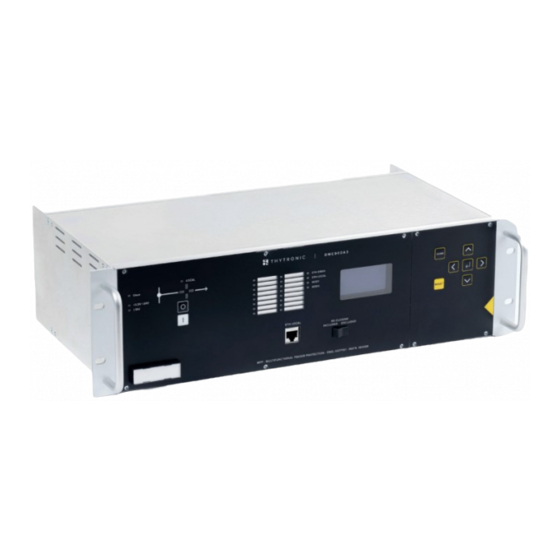
Page 108: Dmc3S - Photo
— DMC3S - PHOTO Keypad Breaker position Display indicator Local Ethernet Switch Breaker port Reclosing control DMC3S - Manual - 08 - 2021... -
Page 109: Dmc3S - Example Of Application To A A3 Primary Substation
Form. Form. factor factor transformer transformer correction correction Neutral Neutral IEC61850 — DMC3S - CE DECLARATION OF CONFORMITY For CE Declaration, please refer to www.thytronic.it in the section covering the DMC3S multifunction panel. DMC3S - Manual - 08 - 2021... - Page 110 Offices: 20139 Milan - Piazza Mistral, 7 - Tel. +39 02 574 957 01 ra - Fax +39 02 574 037 63 Plant: 35127 Padua - Z.I. Sud - Via dell’Artigianato, 48 - Tel. +39 049 894 770 1 ra - Fax +39 049 870 139 0 www.thytronic.it www.thytronic.com...
Need help?
Do you have a question about the DMC3S and is the answer not in the manual?
Questions and answers