Table of Contents
Advertisement
Quick Links
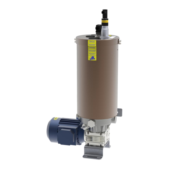
989v2
Multi-outlet electric pump
For 989v2 grease
Manual drafted in compliance
with directive 2006/42
DropsA products can be purchased at DropsA branches and authorised distributors,
Operation and maintenance manual
Original instructions
go to www.dropsa.com/contact or write to sales@dropsa.com
C2287IE - WK 04/21
1
Advertisement
Table of Contents

Subscribe to Our Youtube Channel
Related Manuals for DROPSA 989v2


Summary of Contents for DROPSA 989v2
- Page 1 Multi-outlet electric pump For 989v2 grease Operation and maintenance manual Original instructions Manual drafted in compliance C2287IE - WK 04/21 with directive 2006/42 DropsA products can be purchased at DropsA branches and authorised distributors, go to www.dropsa.com/contact or write to sales@dropsa.com...
- Page 2 Index 3.3.3.3 W ARNINGS TO BE HEEDED IN THE AINTENANCE INTRODUCTION EMOLITION HASES 1. GENERAL INFORMATION 3.4. S AFETY IGNS 3.5. N OISE AND IBRATION NDICATIONS 1.1. G ENERAL INFORMATION 3.5.1. N OISE 1.3. CONTENTS OF THE OPERATION AND 3.5.2. V IBRATIONS MAINTENANCE MANUAL 3.6.
-
Page 3: General Information
989 2, its operation and upkeep. DROPSA S.P.A. will not be held responsible or liable for damage caused by the incorrect use of the documentation. For the purpose of preventing incorrect handling which could cause danger to personnel, it is important to read and comprehend all the documentation that comes with the 989 1. -
Page 4: Property Of The Information
ACHINE the problems that can arise while managing it. The most recent version of this document can be obtained by requesting it from the Sales Technical Office or online at www.dropsa.com. 1.4. Warranty 1.4.1. General Conditions , DROPSA S.P.A. guarantees the 989... - Page 5 from the origin. The transport or shipping expenses, unless otherwise specified in the sale contract, as well as the transfer expenses related to any intervention by the M ’s ANUFACTURER engineers at the User’s site are governed in the sale contract. The M , for the construction of the M , uses materials, organs and mechanisms of...
-
Page 6: Description And Technical Characteristics
1.4.4. Operations that void the warranty Any attempt to disassemble, modify or tamper with a component of the by the user or by MACHINE unauthorised personnel voids the warranty and releases the M from any liability on ANUFACTURER any damage whether to people or things stemming from said tampering. is also released from any responsibility and the warranty on the will be ANUFACTURER... -
Page 7: General Description
dimension of the grease reservoir; type of minimum and maximum level detection sensor (if present), namely induction or laser. 2.1 General description The 989 v2 range of lubrication pumps are particularly suited for plants with progressive systems and can adapt to many needs without mechanical modifications, even after installation. In fact, be choosing a set of components that are perfectly compatible with one another and easy to assemble, you can vary the pressure, the quantity of grease distributed, the type of grease or the type of distribution. - Page 8 Table 1 STANDARD PUMP COMPONENTS Motor Wall mounted support bracket Reducer Pumping element Reservoir Reservoir bleed Capacitive minimum level Grease loading Floor mounted support bracket Optional levels housing 2.2.1 Pumping elements The pump can be supplied both with fixed flow rate pump element (17 cm^3 / min for each pumping element) and with adjustable flow rate pump element (2.5÷17 cm^3 / min for each pumping element).
- Page 9 Continuous sound pressure level < 70 dB(A) (1) If a different product is used, you must ask DROPSA S.p.A. if it is suitable for use. The following characteristics refers to an operating temperature of +20°C [+68°F] The indicated flow rate value refers to the following test conditions: grease with NLGI 2 consistency class, standard environmental conditions (Temperature 20°C [68°F], pressure 1bar [14.5psi]).
-
Page 10: Identification Of The Product
2.4. Identification of the product A label is located on the pump tank that indicates the product code, the power supply voltages and the basic characteristics. - Page 11 In this respect, DropsA S.p.A. requires the use of suitable PPE, namely gloves, eye protection and shoes, while carrying out the various possible operations on the itself.
- Page 12 3.3.1. Lifting and Transport 3.3.1.1 Residual risks present in the Lifting and Transport Phases In the lifting and transport phases, risks are present connected to: operations on the 989 2 by unqualified, untrained, uninformed or incorrectly equipped personnel; incorrect selection of incorrect use of the means of transport and handling of the components of the 989 ...
- Page 13 3.3.2. Installation and operation 3.3.2.1. Residual risks present in the Installation and Operation Phases In the operation and setup phases, risks are present connected to: use of the 989 2 by unqualified, untrained, uninformed or incorrectly equipped personnel; contact with chemical agents, namely, the grease being used by the MACHINE ...
- Page 14 3.3.2.3 Warnings to be heeded in the Installation and Operation Phases In the operation and setup phases, the warnings in this paragraph must be heeded. Carry out transport / positioning / securing of the machine using suitable means. The machine has limited dimensions and a weight of 15 kg or 18 kg, depending on whether it is fitted respectively with a 5 kg or 10 kg grease reservoir.
- Page 15 Use auxiliary equipment only after understanding the indications contained in the related Operation and Maintenance Manuals or after having followed specific and formalised training. Immediately report abnormal operating situations. Do not attempt to make the 989 2 carry out prohibited operations (refer to the indications contained in this manual).
-
Page 16: Safety Signs
3.3.3.3 Warnings to be heeded in the Maintenance and Demolition Phases In the maintenance and demolition phases, the warnings in this paragraph must be heeded. Execution of maintenance and demolition operations must be carried out by qualified and specifically trained personnel. ... -
Page 17: Improper Use
3.5. Noise and Vibration Indications 3.5.1. Noise The 989 2 was designed and built in such a way so as to reduce the noise level emitted during normal operation to a minimum. The noise value detected in the area where the operator is during the work cycle is lower than 70 dB (A). -
Page 18: Transport And Installation
Table 4 – Prohibited fluids PROHIBITED FLUIDS FLUIDS HAZARDS Lubricants with abrasive additives High wear of the contaminated parts Lubricants with silicon additives Seizing of the pump Petrol – solvents – flammable liquids Fire – explosion – damage to the gaskets Corrosive products Corrosion of the pump –... - Page 19 Depending on these variables to achieve a proper supply to the delivery point, it is always necessary to ensure that the pipeline pressure loss plus the pressure required at the lubrication point does not exceed the maximum pressure supplied for pump delivery ...
-
Page 20: Installation Of The Pump
To carry out the task in question, the following Personal Protection Equipment is required: 4.2.1. Installation of the pump To complete the task in question, carry out the following simple steps. Position the pump and secure it to its support (on the wall or floor) by using the appropriate Ø9mm eyelets, (0.354 in) with 4 suitable screws. - Page 21 The unmounted connectors and the power and signals cables must have suitable thickness with regard to the absorption of the machine and type in accordance with regulations in force. They can be ordered separately (see Paragraph 7.1). The pump must be installed in an industrial environment in compliance with prevailing law. In order to prevent dangers of electrocution due to direct or indirect contact with the live parts, the electrical power supply line must be adequately protected with a specific breaker switch with 0.03 Ampere tripping threshold and max tripping time of 1 second.
- Page 22 DO NOT use lubricants that are aggressive to NBR gaskets. If you are unsure, contact the DropsA S.p.A technical office for a detailed list of recommended lubricants. Check the integrity of the pump. ...
-
Page 23: Reservoir Filling
5.2 Reservoir filling ATTENTION: in order to prevent any malfunctions and voiding of the warranty, we recommend topping up the grease without impurities exclusively from the dedicated loading system. Filling the reservoir is carried out by means of the dedicated device complete with filter. 5.3 Adjustable pumping element setting In order to set the progressive pumping element with an adjustable flow, proceed as follows. - Page 24 ATTENTION: only one threshold at a time can be set. Figure 5 – Adjustable pumping element 1 Reference notch 2 Yellow LED: lights when the set value is reached (outlet=ON) 3 Locking ring nut 4 Setting ring nut (manually adjustable after unlocking) 5 Green LED: indicates the correct power supply (24Vdc) 5.5 Operation of the 989 v2 is supplied only with an electric motor and relative connection terminal strip.
- Page 25 Ensure that the pump starts. Ensure the adequate lubrication of the machine (if there are doubts on correct operation, you can contact the DropsA S.p.A. Technical Office and ask for the testing procedure). 5.5.2 Arrest To stop the 989 v2, you must: ...
-
Page 26: Problems And Solutions
No current present. Check the power supply. The pump motor does not work. Replace the motor. This operation may be carried out only by DropsA The motor does not work. S.p.A. engineers. Check the condition of the lines and the relative connections to the Lines disconnected. -
Page 27: Scheduled Maintenance
6.2 Scheduled maintenance The following table lists the periodic inspections, the frequency and the intervention that the maintenance will have to carry out in order to ensure the efficiency of the system over time. Table 6 – Scheduled maintenance times CHECK FREQUENCY INTERVAL INTERVENTION... - Page 28 Figure 6 – Replacement of the pumping element 6.3.2 Replacement of the filter In case of difficulty filling the reservoir, replace the filling nozzle filter. Therefore, operate as follows. Position the electrical disconnect switch on the machine’s power supply line to O – OFF or remove the wall plug.
- Page 29 6.4 Demolition When the 989 v2 has completed its life cycle, before proceeding with the final dismantling, a series of operations must be carried out aimed at minimising the environmental Impact connected with the disposal of the components of the 989 v2 itself, as required by the prevailing regulations on waste disposal.
-
Page 30: Order Information
Table 7 Base 4° 5°/6° 7° 8° 9° 10° 11° data PUMP 989 v2 989 v2 Description DROPSA Code CODE Without reservoir Reservoir 0297402 10kg 0297408 Motor not present STANDARD 3301000 Three-phase 3PH-230/400V 50Hz 280/480V 60Hz electric 3PH-440V-60Hz... - Page 31 The following contains the codes for ordering optional equipment or replacement parts. Figure 8 Figure 8 – Spare parts and optional equipment codes OPTIONAL KITS and ACCESSORIES SPARE PARTS CODE DESCRIPTION CODE DESCRIPTION 0297420C Fixed flow rate pumping element 17 cc/min 2036020 Grease nipple 0297430C...
- Page 32 7.2 Dimensions Figure 9 – Dimensions in mm [in] 5 kg 10 kg A – mm [in] 596 [23.4] 648 [25.5] B – mm [in] 103.5 [4] 122.5 [4.8] C – mm [in] 175 [6.88] 230 [9]...
- Page 33 Contraventions shall be liable for damages. Reprints, even of extracts, are only permitted with the approval of DropsA S.p.A. We reserve the right to implement technical modifications to the machine at any time in order to improve safety, reliability, function and design.
Need help?
Do you have a question about the 989v2 and is the answer not in the manual?
Questions and answers