
Subscribe to Our Youtube Channel
Related Manuals for Walker Edison DT41BL


Summary of Contents for Walker Edison DT41BL
- Page 1 DT41BL, DT41MB ASSEMBLY INSTRUCTIONS For our most up-to-date instructions, to request missing, lost, or broken parts, or for any other Customer Service issues, please visit our website at www.walkeredison.com or call us at 877-207-5906.
-
Page 2: General Assembly Guidelines
General Assembly Guidelines I. Ensure that all parts are available before beginning assembly. II. Follow each step carefully to ensure proper assembly of this product. III. The four main types of hardware used to construct this unit are: wood dowels, cam and bolt, hex-head bolts, and screws. - Page 3 DT41BL, DT41MB Parts List...
- Page 4 DT41BL, DT41MB Hardware Parts List L. Door hinge 4 pcs A. Cam lock 2 pcs M. Screw (4x20mm) 16 pcs B. Cam bolt 2 pcs 2 pcs N. Handle C. Dowel 4 pcs 4 pcs P. Screw (4x22mm) D. Glue tube...
- Page 5 Step 1 Step 2 Insert cam bolts (B) into stand top. Insert dowels (C) into stand top and cam locks (A) into side panels Attach mounting block (5) to stand top (1) using screws (Q). (3 & 4). Attach side panels (3 & 4) to stand top. Tighten cam locks (A) using a screwdriver as shown in Attach nylon strap (S) to stand top (1) using screw (T).
- Page 6 Step 3 Step 4 STICKER X 2 Attach stand base (2) to frame assembly using hex screws (E). Tighten using Turn stand upright. Attach the back panel (7) using nails (J) at the points shown in the diagram. hex wrench (F). Cover cam locks (A) with the provided stickers as shown in the diagram.
- Page 7 Step 5 Step 6 Attach door handles (N) to the stand doors using screws (P). Insert shelf support pins (I) into the stand frame as shown in the diagram. Attach door hinges to the doors using screws (M). Attach shelves (6) to the support pins. Adjust to desired height if necessary. Attach screw (K) to the corner of each door as shown in the diagram.
- Page 8 Step 7 Step 8 Attach doors (8 & 9) to stand frame at the hinges using screws (M). Finished stand should appear as shown in the diagram.
-
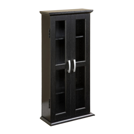
Page 9: Cabinet Top
Step 9 (Optional) We strongly recommend that you attach the unit to your wall to help prevent it from falling over. Due to the wide variety of wall types, the necessary wall screws are not provided. However, we have included illustrations showing installation for the four most common wall types. To attach to the wall, use only wall screws and plugs (if needed) suitable for the particular wall as illustrated below.
Need help?
Do you have a question about the DT41BL and is the answer not in the manual?
Questions and answers