Table of Contents
Advertisement
Quick Links
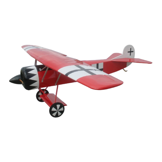
Fokker D-VIII
Instruction Manual
Before commencing assembly,please read these instructions thoroughly.
ALMOST - READY - TO - FLY
ALMOST - READY - TO - FLY
SAFETY PRECAUTIONS
This radio control model is not a toy!
lFirst-time builders should seek advice from people having building
experience in order to assemble the model correctly and to produce
its performance to full extent.
lAssemble this kit only in places out of childrens reach!
lTake enough safety precautions prior to operating this model.
You are responsible for this model s assembly and safe operation!
lAlways keep this instruction manual ready at hand for quick
reference,even after completing the assembly.
lCould cause serious injury or even death
All manuals and user guides at all-guides.com
Thank you for choosing CYmodel
Global : www.cymodel.com
Australia : www.austars-model.com
Italia : www.biellaexpress.com
,
,
Item Nr: CY8016B
SPECIFICATION
Wing Span:2800 mm (110 in)
2
Wing Area:119.7 dm (1856 sq.in)
Fuselage Length: 2100 mm (82.5 in)
Engine : 80-100cc gas engine
Radio : 4 channels ,6 servos
Advertisement
Table of Contents

Subscribe to Our Youtube Channel
Related Manuals for CYmodel Fokker D-VIII


Summary of Contents for CYmodel Fokker D-VIII
- Page 1 All manuals and user guides at all-guides.com Thank you for choosing CYmodel Global : www.cymodel.com Australia : www.austars-model.com Italia : www.biellaexpress.com Fokker D-VIII Item Nr: CY8016B Instruction Manual Before commencing assembly,please read these instructions thoroughly. ALMOST - READY - TO - FLY...
-
Page 2: Before You Begin
All manuals and user guides at all-guides.com REQUIRED FOR OPERATION (Purchase separately) REQUIRED FOR OPERATION (Purchase separately) REQUIRED FOR OPERATION (Purchase separately) REQUIRED FOR OPERATION (Purchase separately) A minimum 4channel radio for airplanes (with 6servos). B B B B Glue And dry batteries. -
Page 3: Install The Aileron Servo
All manuals and user guides at all-guides.com Accessory list for this page. Install the aileron servo HORN 2.6X12mm Tp screw - - - - - 2 - - - - - 8 - - - - - 2 2X10mm screw 4X40 Screw - - - - - 4 - - - - - 2... -
Page 4: Install The Elevator
All manuals and user guides at all-guides.com Accessory list for this page. Main wing&Horizontal/Vertical tail 4X25mm screw - - - - - 4 4X35mm screw - - - - - 3 4mm Washer - - - - - 7 Hinge - - - - - - - - 9 4X25mm screw... -
Page 5: Install The Main Landing Gear
All manuals and user guides at all-guides.com Accessory list for this page. Install the elevator servo HORN Connecting rod head - - - - - 2 HORN - - - - - 2 Connecting rod head - - - - - 4 - - - - - 2 2.5X125mm - - - - - 4... - Page 6 All manuals and user guides at all-guides.com Accessory list for this page. Install the wing support Pressure plate - - - - - 3 3X20mm Tp screw - - - - - -12 Aluminum plate - - - - - -2 4X35mm screw 4X35mm...
-
Page 7: Install The Throttle Servo
All manuals and user guides at all-guides.com Accessory list for this page. Radio Equipment 3X25mm Screw Linkage Stopper - - - - 2 - - - - 1 3X16mm Screw - - - - 5 - - - - 1 3mm rubber band Receiver Receiver... - Page 8 All manuals and user guides at all-guides.com Adjustment. Adjustment Adjust the travel of each control surface to the Adjust the travel of each control surface to the values in the diagrams. values in the diagrams. These values fit general flight capabilities. These values fit general flight capabilities.
Need help?
Do you have a question about the Fokker D-VIII and is the answer not in the manual?
Questions and answers