Table of Contents
Advertisement
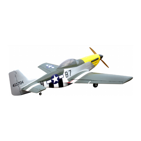
P-51D Mustang
Instruction Manual
Before commencing assembly,please read these instructions thoroughly.
SAFETY PRECAUTIONS
This radio control model is not a toy!
lFirst-time builders should seek advice from people having building
experience in order to assemble the model correctly and to produce
its performance to full extent.
lAssemble this kit only in places out of children s reach!
lTake enough safety precautions prior to operating this model.
You are responsible for this model s assembly and safe operation!
lAlways keep this instruction manual ready at hand for quick
reference,even after completing the assembly.
lCould cause serious injury or even death
Thank you for choosing CYmodel
Global : www.cymodel.com
,
,
Designed and Manufactured by : CYmodel
SPECIFICATION
Wing Span.......2200 mm (86.5 in)
2
Wing Area.......72 dm (1120 sq.in)
Length..............1945 mm (76.5in)
Engine..............35-50cc gas engine
Radio................6 channels, 9 servos
Http : // www.cymodel.com
Advertisement
Table of Contents

Related Manuals for CYmodel P-51D Mustang


Summary of Contents for CYmodel P-51D Mustang
-
Page 1: Instruction Manual
You are responsible for this model s assembly and safe operation! lAlways keep this instruction manual ready at hand for quick reference,even after completing the assembly. lCould cause serious injury or even death Designed and Manufactured by : CYmodel Http : // www.cymodel.com... -
Page 2: Before You Begin
REQUIRED FOR OPERATION (Purchase separately) REQUIRED FOR OPERATION (Purchase separately) A minimum 6 channel radio for airplanes (with 9 servos). Silicone Tube Fuel Filter And dry batteries. CAUTION: Only use a minimum 6 channel radio for Glow engine fuel only. airplanes! (No other radio may be used!) required for engine starting A minimum 6 channel... - Page 3 Accessory list for this page. Install the servo Pin hings 3mm washer 3mm washer - - - - - - 4 - - - - - -6 - - - - - - 4 Rod adjuster Rod adjuster Hinge - - - - 4 - - - - 4 - - - - - - 6 Rod adjuster...
-
Page 4: Install The Main Landing Gear
Accessory list for this page. Install the main landing gear 5X45mm Axletree Rod adjuster - - - - - 1 - - - - - 2 2X8mm screw 3X20mm Tp screw - - - - - 8 - - - - - 1 5.2mm Collar Retainer - - - - - 1... -
Page 5: Install The Elevator Servos
Install the nylon control horn and Accessory list for this page. connect the linkage 3mm Lock nut--2 Pin hings 3mm washer - - - -9 3X16 Screw --2 - - - - - - 2 3mm Lock nut--2 HORN--4 Rod adjuster 3X16 Screw --2 - - - - 2 2.3x10mm Tp Screw... -
Page 6: Install The Tail Wheel
Rudder . Connect the linkage Accessory list for this page. rod to the horn 6X9 screw M4X20mm Cap screw - - - - - - - - - 1 4mm Blind Nut 3X3mm Screw - - - - - - - - 6 - - - - - - 2 Rod adjuster 3.2mm Nylon Collar... - Page 7 Accessory list for this page. Epoxy the horizontal tail to fuselage M3X30mm cap screw - - - - - - 2 M3X20mm Cap screw 3mm Lock Nut - - - - - - 2 3mm Lock Nut 8mm nylon Nut 3.2mm - - - - - 4 M4X10mm screw...
-
Page 8: Assemble The Canopy
Accessory list for this page. Assembly of the full tank After confirming the position(see front of fuel tank). Insert and tighten M3X25mm screw - - - - - 2 the screw. - - - - - - 8 2X8mm screw 3mm Washer - - - - - 2 - - - - - - - - - 8... -
Page 9: Centre Of Gravity
Adjustment. Adjustment. Adjust the travel of each control surface to the Adjust the travel of each control surface to the values in the diagrams. values in the diagrams. These values fit general flight capabilities. These values fit general flight capabilities. Readjust according to your needs and flight level.
Need help?
Do you have a question about the P-51D Mustang and is the answer not in the manual?
Questions and answers