Advertisement
Quick Links
Advertisement

Subscribe to Our Youtube Channel
Related Manuals for Fortis FS26LDEBKSA


Summary of Contents for Fortis FS26LDEBKSA
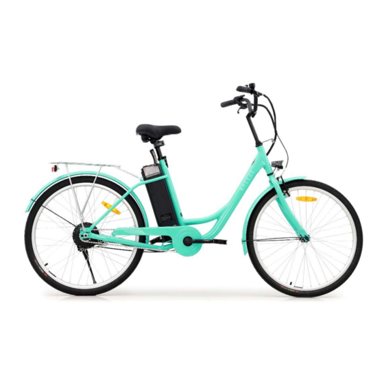
- Page 1 FORTIS 26" CITY LADIES ELECTRIC BIKE FS26LDEBKSA...
-
Page 2: Table Of Contents
Safety & Warnings Overview Assembly Before First Use Operation Charging Cleaning & Care Troubleshooting... -
Page 3: Safety & Warnings
SAFETY & WARNINGS Electric Assisted Bike Regulations The EN 15194 EU standard or EPAC (Electric Power Assisted Cycle) conforms to the following characteristics for electric power assisted bikes: • Motor assistance only starts when the cyclist pedals. • The assistance cuts out as soon as the cyclist stops pedalling. •... - Page 4 • The battery life will vary depending on where you ride it (inclines will reduce power rapidly) and how you ride (assistance mode chosen). The greater the assistance used, the more you'll use the battery and the shorter it will last. This bike is fitted with gears; remember to use them accordingly relative to riding conditions in order to extend battery life.
- Page 5 • Do not over-lubricate; if oil contacts the wheel rim, brake pads or brake disks, this will result in loss of braking performance and an increase in stopping distances. This could potentially cause loss of control, accidents, and injury. Transport It is highly recommended that you do not overload your pedal-assisted bicycle, as this may damage the electrical components or cause malfunctions, such as overheating of the battery or the motor.
-
Page 6: Overview
OVERVIEW Handle grips Bell Control pad Brake lever Handlebars Seat Handlebar stem Battery Headlight Rack Seatpost clamp Front brakes Bike frame Rear sprocket Fork Pedals Rear wheel Front wheel Crankset Chain Tools Supplied 3mm, 4mm & 5mm Multifunction Wrench 6mm Allen & Allen Key (x3) Phillips Head Key... -
Page 7: Assembly
ASSEMBLY Stem & Handlebar Assembly WARNING To prevent steering system damage and possible loss of control, the stem must be inserted enough so that the minimum insertion marks are completely covered (Figure 1). Minimum insertion mark Figure 1 Remove the plastic shipping cap from the bottom of the stem; insert the stem and handlebar assembly into the fork, making sure the stem wedge is loose. - Page 8 Wheel Mounting Make sure the brakes are loose enough to allow the wheel to pass through the brake pads easily. If not already loose, disconnect the front brake by detaching the cable guide from the carrier. Place wheel into fork dropouts (Figure 3a) Install retaining washers with raised lip pointed towards the fork and insert into the small hole of the fork blade.
- Page 9 Brake Adjustment (Figure 4a, 4b and 4c) Pass the inner cable through the inner cable lead, making sure that the brake noodle is properly seated in the outer cable lead (Figure 4a). Set the cable with a clearance of 1mm between each brake pad and the rim, tighten the anchor bolt using the 5mm Allen key (Figure 4b).
- Page 10 Checking your Brakes Press each brake lever to ensure that there is no binding and that the brake pads press firm enough on the rims to stop the bike. The brake pads should be adjusted so they are 1-2mm away from the rim when the brakes are not applied (Figure 5a).
- Page 11 Installing Front Fender & Light Install the preassembled fender to fork legs facing forward with fender bracket positioned behind the fork (Figure 6). Slide a washer onto the mounting bolt and insert through fork and fender bracket. Place the other washer and front light onto the mounting bolt and secure the mounting nut as shown (Figure 7).
- Page 12 Seat Assembly Insert the seat stem into the frame (see Figure 8a and 8b). Pull the quick-release lever free and insert the seat-post to the minimal insertion marker indicated on the seat-post. Insert at least to the minimal indication on the seat stem using rotary movements. You can use grease to help assembly.
- Page 13 Rear Tail Light Remove the insulating paper from the rear tail light, the power supply is now on. Press the BLACK button in the middle of the light to turn the light on. Pressing the button again will make the light flash. Pressing the button a third will turn the light off.
-
Page 14: Before First Use
BEFORE FIRST USE Recommendations and Component Control before Use Before using your bicycle for the first time, you must check that all adjustments have been correctly made. • Check that the front and rear brakes work, check brake pads for wear. •... - Page 15 Seat and Seat-post Make sure that seat and seat-post are correctly tightened and positioned. Bearings • Check that all bearings are properly adjusted and apply lubricant if needed. • Ensure they are not too loose, and that they have not seized up. •...
-
Page 16: Operation
OPERATION Presentation and Electrical Start-Up ELECTRONIC PAD LAYOUT – : Less assistance M : Mode On/Off + : More assistance Starting System Press and hold the “Mode On/Off” button for 5 seconds to turn the bike on. Press and hold for another 5 seconds to turn the bike Off. Press and hold the “+”... -
Page 17: Charging
CHARGING Battery Installation and Locking Install: Press the button under the seat and fold the seat forward. Align the slot on the bottom of the battery with the track on the bike frame, then slide the battery into position, as shown below. Insert the key and turn it clockwise twice to the ON position then fold the seat back into position. - Page 18 Checking the Power Level: Place the RED button of the power switch in the (-) position to turn the power on, press the battery indicator button to check whether the battery power is sufficient. Indicator Battery Status 4 lights on Battery level is full 2-3 lights on Battery level is sufficient, consider...
-
Page 19: Cleaning & Care
CLEANING & CARE Lubrication Only use specific bicycle lubricants. Pedals A few drops every 6 months on the axle. Chain Spray the whole surface every 6 months. Bottom bracket Every 6 months, please check with your authorised dealer. Motor Every year, please check with your authorised dealer. Tips •... -
Page 20: Troubleshooting
TROUBLESHOOTING Error Meaning Troubleshooting Code The brake is in a power-off state. Check whether the left and right brake levers are reset. Check if the fault Brake failure disappears after opening the junction box and unplugging the power-off switch. Contact Kogan.com for support if problem persists. - Page 21 NOTES...
- Page 24 Need more information? We hope that this user guide has given you the assistance needed for a simple set-up. For the most up-to-date guide for your product, as well as any additional assistance you may require, head online to help.kogan.com...
Need help?
Do you have a question about the FS26LDEBKSA and is the answer not in the manual?
Questions and answers