Table of Contents
Advertisement
Quick Links
Advertisement
Table of Contents

Related Manuals for Fortis FS2N1KB12WA


Summary of Contents for Fortis FS2N1KB12WA
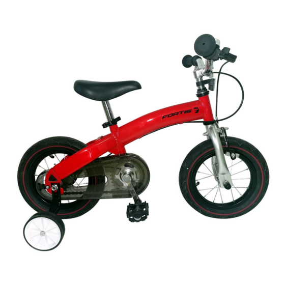
- Page 1 12" 2-IN-1 BALANCE & PEDAL BIKE FS2N1KB12WA...
-
Page 2: Table Of Contents
Contents Safety & warnings Safety checklist Overview Assembly 2-in-1 conversion (balance bike) Cleaning & care Specifications Troubleshooting Notes Note: The illustrations in this manual are for reference only; the components of your bicycle might differ. -
Page 3: Safety & Warnings
SAFETY & WARNINGS This user guide was written to help you get the most performance, comfort, enjoyment and safety when riding your new bicycle. It is important for you to understand your new bike. By reading this user guide before you go out on your first ride, you’ll know how to get the most from your new bicycle. - Page 4 Note: The following manual is only a guide to assist you and is not a complete or comprehensive manual of all aspects of maintaining and repairing your bicycle. Fortis recommend that you consult a bicycle specialist if you have doubts or concerns regarding your experience or ability to properly assemble, repair or maintain your bicycle.
- Page 5 Road Safety Like any sport, bicycling involves risk of injury and damage. You need to know and practice the rules of safe and responsible riding. • In the interest of safer cycling, make sure you read and understand this user guide. Note and perform pre-ride safety checks.
- Page 6 head, not tipped back. Ensure to replace your helmet at least every three years to ensure the structural integrity of the foam. Replace after impact, regardless of lack of visible damage to helmet. • Use bike lanes when available. Also note that in certain states, cars may use bike lanes when turning.
- Page 7 Frame Sizing When selecting a new bicycle, the correct choice of frame size is a very important safety consideration. To determine the correct size bicycle for the rider: • Straddle the assembled bicycle with feet shoulder width apart and flat on the ground. •...
-
Page 8: Safety Checklist
SAFETY CHECKLIST Before every ride, it is important to carry out the following safety checks: Brakes: • Ensure front and rear brakes work properly. • Ensure brake pads are not over worn and are correctly positioned in relation to the rims. •... - Page 9 Chain: • Ensure chain is oiled, clean and runs smoothly. • Extra care is required in wet or dusty conditions. • On bicycles equipped with coaster brakes, check for proper chain tension. • Check to make sure your chain guard is tight and not touching the crank or chain.
-
Page 10: Overview
OVERVIEW 1 Saddle 7 Handlebar 13 Brake lever 2 Seat post 8 Frame 14 Front reflector 3 Clamp 9 Chainguard and chain 15 Brake cable 4 Tyre 10 Crankset 16 Brake 5 Rim 11 Pedal 17 Brake pad 6 Training wheel 12 Bell 18 Front fork... -
Page 11: Assembly
ASSEMBLY Tools Required (Included) Phillips head screwdriver Multi-function wrench Allen keys (5-6mm) Getting Started Open the box and check that all parts are present. We strongly recommend reading this full user guide before beginning assembly. If you aren’t comfortable with the assembly, we recommend bringing your new ride to your local bike shop to have a qualified mechanic put it together for you. - Page 12 Step 1: Front wheel assembly • Place wheel into fork dropouts. Install retaining washers with raised lip pointed towards the fork and insert into the small hole of the fork blade (refer to Figure 1b & 1b). • Install axle nut and securely tighten. Make sure the wheel is centred between the fork blades.
- Page 13 Step 2: Handlebar / stem assembly WARNING: To prevent steering system damage and possible loss of control, the stem must be inserted enough so that the minimum insertion marks are completely covered (refer to figure 2a). Minimum insertion mark Figure 2a Insert the stem and handlebar assembly into the bicycle frame, making sure the stem wedge is loose (figure 2b).
- Page 14 Testing Handlebar and Stem Tightness To test the tightness of the stem, straddle the front wheel between your legs tightly (see figure 2e). Try to turn the handlebar back and forth. The handlebar should not slip or move independently of the front wheel at all.
- Page 15 Step 3: Brakes assembly WARNING: When assembling or adjusting the brakes, make sure the cable anchor nut is tight. Failure to securely tighten the nut could result in brake failure and personal injury. This bike is fitted with cantilever type brakes. The front brake needs to be installed (Refer to figure 3a).
- Page 16 Figure 3c Figure 3b Figure 3d Figure 3f Figure 3e Figure 3g Testing Brake Functions To test the function of the front hand brake, lift the front of the bike and spin the wheel. The wheel should not rub on the brake pads. Next, squeeze the brake lever and take note of the brake pads contacting the side of the wheel.
- Page 17 Step 4: Pedal assembly WARNING: Attachment of an incorrect pedal into a crank arm will cause irreparable damage. Unless the shoulder of the pedal spindle is tight to the face of the crank arm, the pedal may back out causing serious injury or death.
- Page 18 Step 5: Seat assembly WARNING: The seat post must be inserted far enough so that the minimum insertion marks cannot be seen. CAUTION: Operate the quick release lever by hand only. Do not use a hammer or any other tool to tighten the quick release lever (Figures 5b & 5c). Minimum insertion mark Figure 5a Add some white grease to the inside of the seat tube and slide the seat post into the...
- Page 19 Testing Seat Clamp & Post Clamp Tightness After installing the seat post into the bicycle and tightening the clamp, test the tightness of the saddle. Hold the saddle firmly with both hands and try to move it side to side. The seat post should not move at all.
- Page 20 Step 7: Training wheel assembly Use the multi-function wrench to remove the nut, install the training wheel and then tighten the nut (see figure 7a & 7b). Repeat for both sides. Ensure the nut is securely reattached before using. Figure 7a Figure 7b...
- Page 21 Step 8: Tire Inflation: WARNING: Tires must be properly inflated before riding. Never exceed the maximum pressure (PSI) that is listed on the side of the tire. WARNING: Be sure to check that the edge (beads) of both tires are evenly seated the entire way around on both sides of the tire.
-
Page 22: 2-In-1 Conversion (Balance Bike)
2- IN-1 CONVERSION – Pedals, crankset, Bicycle (pedal bike) Balance bike chain guard To convert from bicycle configuration to balance bike, the crankset, chain guard and pedals must be disassembled, and the chain ring stored within the rear hub. Refer to the following steps for disassembly: Remove the chain guard Remove the Left and Right pedals (referring to the Step 4: Pedal Assembly and reversing the instructions), then use a Phillips head screwdriver to loosen the screw near the dropout... - Page 23 Remove the crank set Use 5mm Allen Wrench to loose the bolt above the button bracket (Figure 9c), remove the bolt (9d), then pull separate the chain and crankset and pull the crankset down (9e). Figure 9c Figure 9d Figure 9e Store chain Use the chain storage box to store the chain in the rear hub part (Figure 9f &...
- Page 24 Conversion complete The Balance Bike configuration will look like this when the conversion is complete.
-
Page 25: Cleaning & Care
CLEANING & CARE Lubrication Lubrication should be done at your local bike shop where the “How to” calls for the area to be disassembled and the information provided in this manual about that service is for only those who are comfortable doing such complex maintenance. However, some service and maintenance can and should be performed by the owner and require no special tools or knowledge beyond what is presented in this manual. - Page 26 • Squeeze each adjoining pair of spokes on either side of each wheel between your thumb and index finger. Do they all feel the same? If any feel loose, have your local bike shop check the wheel for tension and trueness. •...
- Page 27 WARNING: Like any mechanical device, a bicycle and its components are subject to wear and stress. Different materials and mechanisms wear or fatigue from stress at different rates and have different life cycles. If a component’s life cycle is exceeded, the component can suddenly and catastrophically fail, causing serious injury or death to the rider.
-
Page 28: Specifications
SPECIFICATIONS 2-5 years old for balance bike configuration Age of use: 3-6 years old for pedal bike configuration Weight limit: 30kg Screw Locking Standard Suggestion Part Name Screw Model Torque Handlebar lock 5-8N.m bell lock 3-5N.m Front Wheel Nut 30-35N.m Rear Wheel Nut 35-40N.m Pedal Install... -
Page 29: Troubleshooting
TROUBLESHOOTING Problem Possible cause Remedy • Excessively worn/chipped chain ring • Replace chain ring, sprockets and or freewheel sprocket teeth. chain. • Chain worn/stretched. • Replace chain. Slipping Chain • Stiff link in chain. • Lubricate or replace link. • Non-compatible chain or chain ring or •... - Page 30 • Brake blocks worn down. • Replace blocks. When applying • Brake block toe-in incorrect. • Correct block toe-in. the brakes, they • Brake blocks/rim dirty or wet. • Clean blocks and rim. squeal/squeak • Brake arms loose. • Tighten mounting bolts. •...
-
Page 31: Notes
NOTES... - Page 32 Need more information? We hope that this user guide has given you the assistance needed for a simple set-up. For the most up-to-date guide for your product, as well as any additional assistance you may require, head online to help.kogan.com...
Need help?
Do you have a question about the FS2N1KB12WA and is the answer not in the manual?
Questions and answers