Advertisement
Quick Links
Advertisement

Subscribe to Our Youtube Channel
Related Manuals for Fortis 700C BAFANG


Summary of Contents for Fortis 700C BAFANG
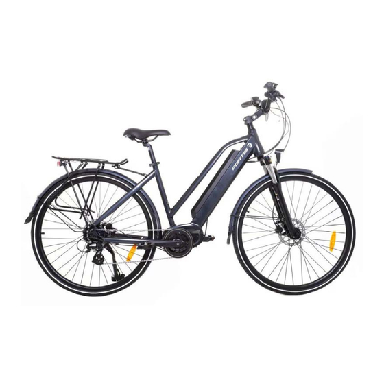
- Page 1 700C BAFANG MID-DRIVE ELECTRIC HYBRID (MOUNTAIN BIKE) FS7MDMBTBMA...
-
Page 2: Table Of Contents
Safety & Warnings Overview Assembly Before First Use Operation Specifications Troubleshooting... -
Page 3: Safety & Warnings
SAFETY & WARNINGS Electric Assisted Bike Regulations The EN 15194 EU standard or EPAC (Electric Power Assisted Cycle) conforms to the following characteristics for electric power assisted bikes: • Motor assistance only starts when the cyclist pedals. • The assistance cuts out as soon as the cyclist stops pedalling. •... - Page 4 • The battery life will vary depending on where you ride it (inclines will reduce power rapidly) and how you ride (assistance mode chosen). The greater the assistance used, the more you'll use the battery and the shorter it will last. This bike is fitted with gears; remember to use them accordingly relative to riding conditions in order to extend battery life.
- Page 5 • Do not over-lubricate; if oil contacts the wheel rim, brake pads or brake disks, this will result in loss of braking performance and an increase in stopping distances. This could potentially cause loss of control, accidents, and injury. Transport It is highly recommended that you do not overload your pedal-assisted bicycle, as this may damage the electrical components or cause malfunctions, such as overheating of the battery or the motor.
-
Page 6: Overview
OVERVIEW Bell Control pad Brake lever Handle grips Seat Handlebar stem Bike frame Seatpost clamp Battery Rear sprocket Fork Front brakes Rear derailleur Pedals Front wheel Crankset Rear wheel Chain Tools Supplied Multifunction Wrench 6mm Allen & 3mm, 4mm & 5mm Allen Key (x3) Phillips Head Key... -
Page 7: Assembly
ASSEMBLY Stem Assembly Stem fitted in the head tube with an expanding bolt (Figure 1). Insert the stem into the head tube, respecting the minimum insertion limit as indicated on the stem and tighten the expanding bolt to 18Nm. Before tightening the stem, make sure that it is in-line with the front wheel. Figure 1 WARNING To prevent steering system damage and possible loss of... - Page 8 Wheel Mounting Place the wheel in a central position between the frame dropouts and the fork. Install the quick release lever and ensure each side has a spring. Tighten the adjusting nut. Close the quick-release system. In order to prevent it coming loose, it is necessary to turn the adjusting nut such that the closing force of the release lever is at least 12 daN (about 12 Kg).
- Page 9 Brake Adjustment Note: When the front wheel is installed properly, the disc brake rotor should be centered between the brake pads, recheck the disc brake is installed well in the following steps. DO NOT pull on the lever before the wheel is installed. It may cause the brake pads to bind together making it is difficult to separate them without the proper tools and expertise.
-
Page 10: Before First Use
BEFORE FIRST USE Recommendations and Component Control before Use Before using your bicycle for the first time, you must check that all adjustments have been correctly made. • Check that the front and rear brakes work, check brake pads for wear. •... - Page 11 Seat and Seat-post Make sure that seat and seat-post are correctly tightened and positioned. Bearings • Check that all bearings are properly adjusted and apply lubricant if needed. • Ensure they are not too loose, and that they have not seized up. •...
-
Page 12: Operation
OPERATION 1. Battery 1.1. Use the Battery Properly • The battery can always be charged at any time no matter how much power is left. However, in the following cases, you should have the battery fully charged. Make sure to use the specified charger to charge the battery. •... - Page 13 2. Display 2.1 Appearance and Dimensions The shell is made of PC (poly carbonate). The liquid crystal interface is made of hard hardness acrylic. 94mm ø31.80mm/25.4mm/22.2mm 82mm 44mm 22.20mm 41mm...
- Page 14 2.2 Function Overview and Key Definitions Function Overview • Speed display: displaying the real-time SPEED, the max speed MAXS and the average speed AVG. • Km or mile: the user can set the unit of distance as km or mile according to personal habit.
- Page 15 Items to be Shown on the Display: Maintenance warning Menu Speed display Battery level Distance mode Speed mode Headlight Fault prompt Riding distance display Walk assistance Assist mode Speed mode: Average speed (AVG km/h), maximum speed (MAXS km/h) Speed display: Display of the speed, km/h or mile/h Battery level: 10-segment battery indication.
- Page 16 Button overview Headlight Increase (+) Power Decrease (–) Mode (i) 3. Normal Operation 3.1. Turning on • Turn on the power. Press and hold the Power button for 2 seconds to power on the display. • To turn the display off, press and hold the Power button for another 2 seconds •...
- Page 17 3.3. Distance Mode and Speed Mode Switch Press the Mode (i) button to switch distance/speed display information, giving a display of single-trip distance (TRIP km), accumulated distance (TOTAL km), maximum riding speed (MAXS km/h), average riding speed (AVG km/h), Range and OC sequentially. Mode Switch Interface Note: Range and OC settings are displayed in the menu but are non-functioning for this...
- Page 18 3.4. Headlight/ Backlight Switch • After pressing and holding the Headlight button for 2 seconds, both the backlight of the display and the headlight (needing the support of the controller) will be turned on. • Hold and press the Headlight button again for 2 seconds to power off the headlight and the display backlight.
- Page 19 3.5. Walk Assistance Mode After pressing and holding the Decrease (–) button for 2 seconds, the electric bicycle enters the state of walk assistance and the symbol WALK is displayed in the field of assistance mode. Once the Decrease (–) button is released, the electric bicycle will exit the mode of walk assistance.
- Page 20 Table for Battery Level Check: Number of Number of Battery status Battery status Segments Segments ≥90% 35%≤C<45% 80%≤C<90% 25%≤C<35% 70%≤C<80% 15%≤C<25% 60%≤C<70% 5%≤C<15% 50%≤C<60% Border blinking C<5% 45%≤C<50% 4. Parameter Setting Setting Preparation When the display is active, pressing the Mode (i) button twice (the interval between the two pressing actions should be shorter than 0.3 seconds), the system will enter the MENU parameter setting state, in which the display parameters can be set.
- Page 21 Data Reset: After pressing the Mode (i) button (the interval between the two pressing actions should be shorter than 0.3 seconds), the display enters the MENU state. In this state, the speed field displays ‘tC’ and then also displays ‘y’ after pressing the Increase (+) button. At this moment, the temporary data, including maximum speed (MAXS), average speed (AVG) and single-trip distance (TRIP) can be cleared.
- Page 22 Light Sensitivity: When the speed field displays bL0, press the Increase (+) or Decrease (–) buttons to display a figure between 0 to 5. 0 represents the shutdown of light-sensing function. As the figure increases, light sensitivity gradually increases. After this setting, press the Mode (i) button for shorter than 0.3 seconds to enter the setting interface of backlight brightness.
- Page 23 Automatic Off Time: When the speed field displays OFF, press the Increase (+) or Decrease (–) buttons to display a figure between 1 to 9. This figure indicates the minute that it takes to automatically shut down the display. After this setting, press the Mode (i) button for shorter than 0.3 seconds to enter the setting interface of maintenance warning.
- Page 24 Wheel Diameter View: When the speed position displays Wd, the distance field displays the wheel diameter setting. This is set to 27 inches and cannot be adjusted. After viewing, press the Mode (i) button for less than 0.3 seconds to enter the setting interface of speed limit view.
-
Page 25: Specifications
SPECIFICATIONS Power Supply 36V/48V Rated Current 10mA Maximum Operating Current 30mA Power-off Leakage Current <1uA Operating Current Supplied to the Controller 50mA Operation Temperature -18 ~ 60˚C Storage Temperature -30 ~ 70˚C Waterproof Grade IP65 Storage Humidity 30%-70% TROUBLESHOOTING Error Code Definitions The MAX-C966 display can give warnings on bicycle faults. - Page 26 Definitions of error codes are listed in the table below: Error Code Error Description Error-shooting Method "03" is displayed in the field The braking system has Check whether a brake for speed display. been applied. cable is stuck. “04”is displayed in the field The throttle has not returned Check whether the throttle for speed display.
- Page 27 NOTES...
- Page 28 Need more information? We hope that this user guide has given you the assistance needed for a simple set-up. For the most up-to-date guide for your product, as well as any additional assistance you may require, head online to help.kogan.com...
Need help?
Do you have a question about the 700C BAFANG and is the answer not in the manual?
Questions and answers