Download Print this page
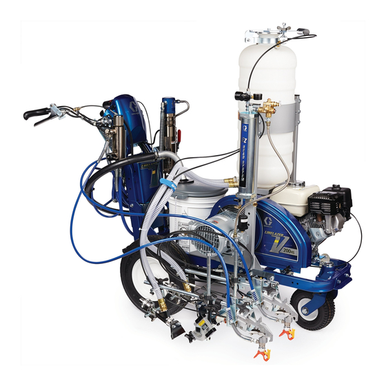
Graco LineLazer 200HS Installation, Operation & Parts

Graco LineLazer 200HS Installation, Operation & Parts

Pressurized bead system
Hide thumbs Also See for LineLazer 200HS:

Advertisement

Quick Links

Installation - Operation - Parts
Complete Pressurized Bead System for
LineLazer 200HS/DC/MMA and LineLazer
250SPS/DC/MMA
Models:
25R268 1-Gun LL200
25R270 1-Gun LL250
25R267 2-Gun LL200
25R269 2-Gun LL250
80 psi (.55 MPa, 5.5 bar) Maximum Working Pressure
Important Safety Instructions
Read all warnings and instructions in the striper manual. Be familiar
with the controls and the proper usage of the equipment. Save
these instructions.
- For professional use only -
HS/MMA
SPS/MMA
HS/DC/MMA
SPS/DC/MMA
Related Manual
Bead Gun Kit
LLIV 200HS Repair
LLV 200HS/DC Repair and Parts
LLV 200MMA Operation, Repair, Parts 3A6466
250DC Repair
332230T
EN
332226
311021
3A3390
334053

Advertisement

loading
Need help?

Need help?

Do you have a question about the LineLazer 200HS and is the answer not in the manual?

Questions and answers

Summary of Contents for Graco LineLazer 200HS

  • Page 1 Installation - Operation - Parts Complete Pressurized Bead System for LineLazer 200HS/DC/MMA and LineLazer 332230T 250SPS/DC/MMA - For professional use only - Models: 25R268 1-Gun LL200 HS/MMA 25R270 1-Gun LL250 SPS/MMA 25R267 2-Gun LL200 Related Manual HS/DC/MMA Bead Gun Kit...
  • Page 2 Warnings Warnings The following warnings are for the setup, use, grounding, maintenance, and repair of this equipment. The exclamation point symbol alerts you to a general warning and the hazard symbols refer to procedure-specific risks. When these symbols appear in the body of this manual or on warning labels, refer back to these Warnings. Product-specific hazard symbols and warnings not covered in this section may appear throughout the body of this manual where applicable.
  • Page 3 Warnings WARNING SKIN INJECTION HAZARD High-pressure fluid from gun, hose leaks, or ruptured components will pierce skin. This may look like just a cut, but it is a serious injury that can result in amputation. Get immediate surgical treatment. • Do not spray without tip guard and trigger guard installed.
  • Page 4: Tools Needed

    Tools Needed: CE Safety Checklist (To be completed during non-factory installation) Covers and shrouds for moving parts are in place (see guard installation section). Fasteners, belts, covers, grills, and compressor are tight-mounted securely. Read and understand all warnings and instructions in this manual and the striper manual. Tools Needed: •...
  • Page 5 Operation for LL200 and LL250 Operation for LL200 and LL250 Component Identification Ref. Description Ref. Description Pressure Relief Valve Funnel Bead Tank Gauge Wing Nut Pressure Regulator Valve Compressor Bypass Switch Air Tank Gauge Regulator Unloader Safety Relief Valve 332230T...
  • Page 6: Pressure Relief Procedure

    Pressure Relief Procedure Pressure Relief Procedure 3. Loosen wing nut (2) until it reaches end of threads. Follow the Pressure Relief Procedure whenever If any remaining pressure is in bead tank, it will be you see this symbol. released through seal while wing nut secures lid to hopper.
  • Page 7 200HC/DC/MMA Pressurized Bead System Kit 25R268 200HC/DC/MMA Pressurized Bead System Kit 25R268 Assemble Compressor Mounting 3. Assemble hopper basket (XX) and base with hardware as shown below. Use 9/16 in. wrench to and Drive Components snug screws. Loosen all six screws 1/4 turn. 3A3788 NOTE: Glass bead system and paint guns can be mounted on either side of sprayer.
  • Page 8 200HC/DC/MMA Pressurized Bead System Kit 25R268 Complete Frame Assembly 2. Install plastic end caps (ZZ) into frame. Use rubber mallet to pound end caps into place. NOTE: If desired, rotate recoil 90° counter-clockwise. ti21500a 1. Use 9/16 wrench to tighten bottom screws (MM) to ti20884a hardware shown.
  • Page 9 LL200 Compressor Installation LL200 Compressor Installation Tools Needed: 5. Using same bolts (bb) and lock nuts (22), install air tank bracket (3). • 2.5 mm Allen wrench • 1/4 in. Allen wrench • 1/8 in. Allen wrench • 7/16 in. wrench •...
  • Page 10 LL200 Compressor Installation 7. Remove oil breather from compressor. Pour 4 oz. of included compressor oil into compressor through breather port. Verify oil is above red dot in sight glass. NOTE: Oil level will change at a slower rate than poured as it descends into the crankcase.
  • Page 11 LL200 Compressor Installation 12. Slowly pull the starter rope to rotate shaft so that 14. Align teeth and slide flex insert (9) all the way into the shaft keyway (5) faces up. Place the key (2) into coupler (8). the shaft keyway. A light tap with a rubber mallet may be needed to ensure the key seats completely.
  • Page 12 LL200 Compressor Installation 16. Start two set screws (7) into second coupler (8). Slide coupler (8) over flex insert (9). Coupler (8) should stay in position, if not it may need to be held until the next step. 17. Ensure keyway on coupler shaft (15) is on top, rotate as necessary.
  • Page 13 LL200 Compressor Installation 19. Vertical Alignment: hold compressor assembly (17) 21. Place guard (20) over mounting bracket (11). such that from the side both couplers (17) and flex Located longest slot on vertical sides (3rd from insert (9) are aligned axially. When properly aligned, top), and align with mounting tabs.
  • Page 14 LL200 Compressor Installation Bead Tank Mounting 3. Install 36 in. nylon air line (dd) from top of regulator to swivel fitting on top of bead hopper. Cut air line 1. Place bead tank on supporting base with outlet to desired length. Push air line into fitting until end fittings facing compressor.
  • Page 15 LL250 Pressurized Bead System Kit 25R270 LL250 Pressurized Bead System Kit 25R270 Assemble Compressor Mounting 4. Loosely install two screws (M) and two locknuts (N) through bottom of frame mount. Use 9/16 in. and Drive Components wrench to fully tighten. 3A3788 1.
  • Page 16 LL250 Pressurized Bead System Kit 25R270 7. Make sure left and right frame mounts are aligned. 9. Assemble hopper bracket (X) and base (Y) with The left leg should mirror the right leg location from hardware provided. Install carriage bolts with the LL250 frame cross member.
  • Page 17 LL250 Compressor Installation LL250 Compressor Installation Tools Needed: 5. Using a 9/16 in. wrench and screws, mount the air tank to the new air tank bracket. • 2.5 mm Allen wrench • 4.0 mm Allen wrench • 1/4 in. Allen wrench •...
  • Page 18 LL250 Compressor Installation 7. Remove hopper. Locate belt shroud. Loosen screw 10. Install coupler mounting plate (5) onto pulley with (A) and lift belt shroud (B). two shoulder screws (18) and serrated nuts (19). Position slot on back of pulley up and move serrated nut with finger to accept shoulder bolt threads.
  • Page 19 LL250 Compressor Installation 11. Start two set screws (7) into coupler (8). Slide Remove existing frame bolts (12) and washers coupler (8) over coupler mount (3), assure key (6) is (13) from frame. Using the same bolt and still in position. Push coupler (8) flush against washers, secure mounting bracket (10) to frame.
  • Page 20 LL250 Compressor Installation 14. Start two set screws (7) into second coupler (8). 15. Ensure keyway on coupler shaft (15) is on top, Slide coupler (8) over flex insert (9). Coupler (8) rotate as necessary. Place second key (6) in should stay in position, if not it may need to be held keyway of coupler shaft (15).
  • Page 21 LL250 Compressor Installation 17. Vertical Alignment: hold compressor assembly (17) NOTICE such that from the side both couplers (8) and flex Performing the following step incorrectly may result in insert (9) are aligned axially. When properly aligned, improper alignment of the two rotating couplers. This tighten four nuts (19) on studs (16) to mounting may cause premature wear and require replacement bracket (10) to 150-160 in-lb (16.9-18 N•m).
  • Page 22 LL250 Compressor Installation 19. Place guard (20) over mounting bracket (11). 21. Use a 11/16 in. wrench and a 9/16 in. backup Located longest slot on vertical sides (3rd from wrench to attach the braided hose from the air tank top), and align with mounting tabs.
  • Page 23: Maintenance

    Maintenance Maintenance Routine maintenance is important to ensure proper operation of your compressor. Maintenance includes performing routine actions to keep your compressor in operation and prevent trouble in the future. Activity Interval Replace air filter Every 200 hours, or as needed Change oil* After first 50 hours, then every 200 hours or three months * Drain oil by siphoning from fill port.
  • Page 24 Maintenance Bead Tank Mounting NOTE: Position handle to best suit filling needs. Loosen bolt (AA) to help swivel, then retighten. 1. When only one bead tank is being installed, it should be placed on the side of the frame furthest from the compressor to best distribute weight.
  • Page 25: Operation

    Operation Operation Charging Air Tank Setting Bead Hopper Pressure 1. Start engine and engage clutch. Compressor is The pressure regulator valve (5) controls pressure sent now engaged. from the air tank to the bead tank. The regulator is set to 0 pressure from the factory. 2.
  • Page 26 Operation Bead Timing With Gun 1. Use air flow restrictor valves to help time the 3. Turning the valve clockwise will delay gun opening and closing of the bead guns to best opening/closing time. Turning the valve match the start and stop of paint lines. counter-clockwise will speed up gun opening/closing time.
  • Page 27 Determining Bead Application Pressure Determining Bead Application Pressure The table below lists bead delivery rates for 4 inch (10 3. Under bead gun nozzle size, find nearest value cm) lines with standard size highway beads. compared to Step 2. • Wider lines use multiples of 4 in.
  • Page 28 Determining Bead Application Pressure Filling Bead Hopper 1. Move compressor bypass switch (9) to horizontal 4. Place funnel (1) into opening. Pour beads into position to disengage compressor or turn engine off. hopper. Beads should not be filled to a height higher than shown in figure below.
  • Page 29 Determining Bead Application Pressure 0 to 8 in. Line Setup 2 Tank 1 Gun Setup For wider lines it may be necessary to mount bead gun Connect “Y” fitting as shown below to allow two tanks as shown below. to flow into one gun. ti20977a 8 - 12 in.
  • Page 30 Determining Bead Application Pressure Double Drop Setup Use a “Y” fitting to create a dual bead gun setup for double drop beads. Splice exit hose on bottom of air switch and branch into both guns. ti20564a 332230T...
  • Page 31 Notes Notes 332230T...
  • Page 32 Parts - Model 25R268 Parts - Model 25R268 332230T...
  • Page 33 Parts - Model 25R268 Parts List - 25R268 Ref. Part Description Qty. Ref. Part Description Qty. 52▲ 16C394 LABEL, safety, warning, entangle 25U927 KIT, compressor 16U025 KIT, tank, pressure, includes 25R271 KIT, obsolete compressor 53a-53o replacement** 156971 FITTING, nipple, short 1c†...
  • Page 34 Parts - Model 25R270 Parts - Model 25R270 332230T...
  • Page 35 Parts - Model 25R270 Parts List - Model 25R270 Ref. Part Description Qty. Ref. Part Description Qty. 156971 FITTING, nipple, short 25U927 KIT, compressor 53b 187357 ELBOW,street 25R272 KIT, obsolete compressor 16W088 GAUGE, air pressure replacement** 53d 17C463 FITTING, tee, street, modification 1c†...
  • Page 36: Graco Standard Warranty

    With the exception of any special, extended, or limited warranty published by Graco, Graco will, for a period of twelve months from the date of sale, repair or replace any part of the equipment determined by Graco to be defective.