Table of Contents
Advertisement
Operation
™
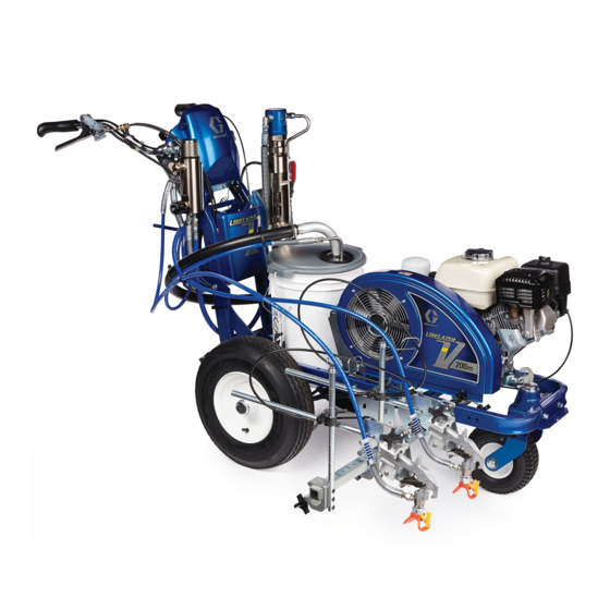
LineLazer
V 200
Standard Series and High Production (HP) Series
For the application of line striping materials.
For professional use only.
For outdoor use only.
Not for use in explosive atmospheres or hazardous locations.
Maximum Operating Pressure: 3300 psi (22.8 MPa, 228 bar)
Important Safety Instructions
Read all warnings and instructions in this manual and in related manuals before using the equipment.
Be familiar with the controls and the proper usage of the equipment.
Save these instructions.
Related Manuals:
3A3390
Parts
311254
Gun
LineLazer V 200
Standard Series
Use only genuine Graco replacement parts.
The use of non-Graco replacement parts may void warranty.
& 200
HS
DC
309277
Pump
3A3428
Auto-Layout Applications Methods
HS
Airless Line Stripers
LineLazer V 200
HS
High Production Series
3A3426E
EN
LineLazer V 200
DC
Advertisement
Table of Contents

Subscribe to Our Youtube Channel
Related Manuals for Graco LineLazer V 200HS


Summary of Contents for Graco LineLazer V 200HS
- Page 1 Related Manuals: 3A3390 Parts 309277 Pump 311254 3A3428 Auto-Layout Applications Methods LineLazer V 200 Standard Series LineLazer V 200 LineLazer V 200 High Production Series Use only genuine Graco replacement parts. The use of non-Graco replacement parts may void warranty.
-
Page 2: Table Of Contents
LineLazer V LiveLook Display ....26 Graco Information ......70 Standard Series . -
Page 3: Models
Models Models LineLazer V 200HS & 200DC Model: Series Standard Standard HP Auto HP Auto HP Auto HP Reflective HP Reflective HP Reflective HP Reflective 1 Manual Gun 2 Manual Guns 1 Auto Gun 1 Manual Gun 2 Auto Guns... -
Page 4: Warnings
• Check hoses and parts for signs of damage. Replace any damaged hoses or parts. • This system is capable of producing 3300 psi. Use Graco replacement parts or accessories that are rated a minimum of 3300 psi. • Always engage the trigger lock when not spraying. Verify the trigger lock is functioning properly. - Page 5 Warnings CARBON MONOXIDE HAZARD Exhaust contains poisonous carbon monoxide, which is colorless and odorless. Breathing carbon monoxide can cause death. • Do not operate in an enclosed area. EQUIPMENT MISUSE HAZARD Misuse can cause death or serious injury. • Do not operate the unit when fatigued or under the influence of drugs or alcohol. •...
- Page 6 Warnings TOXIC FLUID OR FUMES HAZARD Toxic fluids or fumes can cause serious injury or death if splashed in the eyes or on skin, inhaled, or swallowed. • Read Safety Data Sheets (SDSs) to know the specific hazards of the fluids you are using. •...
-
Page 7: Battery Disposal
Warnings Important Laser Information for Units with Laser Option LASER LIGHT HAZARD: AVOID DIRECT EYE CONTACT Eye exposure to Class IIIa3/3R levels of laser light can potentially present an eye (retinal) injury hazard, including spot blindness or other retinal injury. To avoid direct eye exposure: •... -
Page 8: Tip Selection
Tip Selection Tip Selection (cm) (cm) (cm) (cm) LL5213* 2 (5) LL5215* 2 (5) LL5217 4 (10) LL5219 4 (10) LL5315 4 (10) LL5317 4 (10) LL5319 4 (10) LL5321 4 (10) LL5323 ... -
Page 9: Component Identification (Llv 200Hs)
Component Identification (LLV 200HS) Component Identification (LLV 200 Engine STOP Display *12 12 Volt Battery Manual Spray Gun Trigger *13 Gun Actuators / Solenoids Prime/Spray Valve *14 Layout Laser Filter Engine Kill Switch Trigger Lock Identification Label Engine/Controls *17 Auto Spray Gun Control Button Drain and Siphon Tubes Pump ON/OFF Lever *HP Auto Series only. -
Page 10: Component Identification (Llv 200Dc)
Component Identification (LLV 200DC) Component Identification (LLV 200 Engine STOP Display *12 12 volt battery Manual Spray Gun Trigger *13 Gun Actuators / Solenoids Prime/Spray Valve *14 Layout laser Filter Engine kill switch Trigger Lock Identification label Engine/Controls *17 Auto Spray Gun Control Button Drain and siphon tubes Pump ON/OFF lever *HP Auto Series only. -
Page 11: Grounding Procedure (For Flammable Flushing Fluids Only)
Grounding Procedure (For Flammable Flushing Fluids Only) Grounding Procedure 1. Perform Grounding Procedure (For Flammable Flushing Fluids Only), page 11. (For Flammable Flushing Fluids 2. Set pump switch to OFF. Turn engine OFF. Only) This equipment must be grounded to reduce the risk of static sparking. -
Page 12: Setup/Startup
Setup/Startup Setup/Startup 6. Set pump switch to OFF. Both for 200 This equipment stays pressurized until pressure is manually relieved. To help prevent serious injury from pressurized fluid, such as skin injection, splashing fluid ti27504a ti23144a and moving parts, follow the Pressure Relief Procedure when you stop spraying and before 7. - Page 13 Setup/Startup 10. Start engine: 11. After engine starts, move choke to open. a. Move fuel valve to open. ti27766a ti27616a 12. Set throttle to desired setting. b. Move choke to closed. ti27618a ti28152a ti27617a 13. Digital display is functional after engine starts. c.
- Page 14 Setup/Startup 14. Set pump switch to ON (pump is now active). For perform this step for first color/pump to be primed. High-pressure spray is able to inject toxins into the body and cause serious bodily injury. Do not stop leaks with hand or rag. 18.
-
Page 15: Switchtip And Guard Assembly
Setup/Startup SwitchTip and Guard Assembly To avoid serious injury from skin injection do not put your hand in front of the spray tip when installing or removing the spray tip and tip guard. 1. Engage trigger lock. Use end of SwitchTip to press OneSeal into tip guard, with curve matching tip bore. -
Page 16: Gun Placement
Gun Placement Gun Placement Install Guns Another option can be to swing the gun out at an angle and rotate the tip guard. This results in better visibility for the user. 1. Insert guns into gun holder. Tighten clamps. ti27777a Position Gun 2. -
Page 17: Select Guns (Hp Auto Series)
Gun Placement Select Guns (HP Auto Series) 2. Use the auto gun trigger control to actuate guns. 1. Use the gun selector buttons to determine which guns are active. Each gun selector has 3 settings: continuous line, OFF and programmed line pattern. ti27881a ti27784a 4 Examples:... -
Page 18: Gun Positions Chart
Gun Placement Gun Positions Chart ti27786a One line One line up to 24 in. (61cm) wide Two lines One line or two lines to spray around obstacles One gun curb Two gun curb Two lines or one line up to 24 in. (61 cm) wide 3A3426EOperation... -
Page 19: Gun Arm Mounts
Gun Placement Gun Arm Mounts 4. Tighten gun arm knob into gun arm mounting slot. This unit is equipped with front and rear gun arm mounts. ti27798a NOTICE Make sure all hoses, cables, and wires are properly routed through brackets and do NOT rub on tire. Contact with tire will result in damaged hoses, cables, and wires. -
Page 20: Installation
Gun Placement Installation No fluid spray 2. Turn screw in handle clockwise if spray icon 1. Install vertical gun mount onto gun bar. appears before fluid spray starts. ti27801a NOTE: Make sure all hoses, cables, and wires are ti27802a properly routed through brackets. No spray icon Trigger Sensor Adjustment 3. -
Page 21: Gun Cable Adjustment
Gun Placement Gun Cable Adjustment 3. Insert plastic cable retainer into cable bracket hole. Adjusting the gun cable will increase or decrease the gap between the trigger plate and the gun trigger. To adjust trigger gap, perform the steps below. Standard Series ti27806b 4. -
Page 22: Straight Line Adjustment
Gun Placement Straight Line Adjustment 4. Roll the striper. Repeat steps 2 and 3 until striper rolls straight. Tighten bolt on wheel alignment plate to lock the new wheel setting. The front wheel is set to center the unit and allow the operator to form straight lines. -
Page 23: Dot Laser (If Applicable)
Gun Placement Dot Laser (if applicable) 4. Route wires from the switch to the battery and con nect to the (+) and (-) terminals. LASER LIGHT HAZARD. Avoid direct eye contact. 1. Remove battery cover. ti27818a 5. Connect the switch leads to the wire harness. ti27887a 6. -
Page 24: Cleanup
Cleanup Cleanup 4. Clean filter, guard and SwitchTip in flushing fluid. This equipment stays pressurized until pressure is manually relieved. To help prevent serious injury from pressurized fluid, such as skin injection, splashing fluid TI3375A and moving parts, follow the Pressure Relief FLUSH Procedure when you stop spraying and before 5. - Page 25 Cleanup Standard Series 3A3426EOperation...
-
Page 26: Linelazer V Livelook Display
LineLazer V LiveLook Display LineLazer V LiveLook Display Standard Series 3A3426EOperation... -
Page 27: Initial Setup (Standard Series)
LineLazer V LiveLook Display Initial Setup (Standard Series) US Units Pressure = psi Volume = gallons The initial setup prepares the striper for operation based Distance = feet on a number of user entered parameters. Language Line Thickness = mil selections and the units of measure selections can be SI Units set before you start or changed later. - Page 28 LineLazer V LiveLook Display 3. Press to select Setup/Information. 6. Push to start calibration. ti27826a 7. Move striper forward. Keep unit aligned with steel tape. 8. Stop when chosen part of unit aligns with 26-ft (8m), or distance entered, on steel tape (25-ft./ 7.6m ti27827a distance).
-
Page 29: Striping Mode (Standard Series)
LineLazer V LiveLook Display Striping Mode (Standard Series) 200DC 200H ti27889a Operating in Striping Mode Ref. Description 1. Make sure engine is running. Resets Distance, Gallons, Mils Job logging 2. Set pump switch to ON. Scroll between menu screens Line width adjustment buttons Auto gun buttons MIL thickness. -
Page 30: Measure Mode (Standard Series)
LineLazer V LiveLook Display Measure Mode (Standard Series) 2. Press and release . Move striper forwards or backwards. (Moving backwards is a negative Measure Mode replaces a tape measure to measure distance.) distances when laying out an area to be striped. 1. -
Page 31: Setup/Information
LineLazer V LiveLook Display Setup/Information to select Setup/Information. Press to select Language. See Language, page 27. See Calibration, page 27. See Settings, page 32. See Information, page 33. 3A3426EOperation... -
Page 32: Settings
LineLazer V LiveLook Display Settings to select Setup/Information. Press open Settings Menu. Chooses the machine type. Necessary for accurate gallon counting. to set time and date. Set units with to adjust screen contrast to the desired value. ti27839b 3A3426EOperation... -
Page 33: Information
LineLazer V LiveLook Display Information to select Setup/Information. Press open Information Menu. Displays and logs life data and striper information. View and test functionality of components. Stroke Counter Touch Pad Buttons Pressure Transducer Engine Voltage Distance Sensor Battery Voltage Logs last four error codes that occurred. Code Description 02 = Over pressure 03 = No transducer detected... -
Page 34: Hp Auto Series And Hp Reflective Series
HP Auto Series and HP Reflective Series HP Auto Series and HP Reflective Series 3A3426EOperation... -
Page 35: Linelazer V Livelook Display
LineLazer V LiveLook Display LineLazer V LiveLook Display HP Auto Series STRIPING SCREEN MEASURE MODE LAYOUT MODE SETTING/INFO 200DC 9.00 10.00 11.00 MEASURE MODE 0. 00 ¹ 0. 00 ¹ 0. 00 ¹ 0. 00 ¹ 0. 00 ¹ 0. 00 ¹... -
Page 36: Initial Setup (Hp Auto Series)
LineLazer V LiveLook Display Initial Setup (HP Auto Series) US Units Pressure = psi Volume = gallons The initial setup prepares the striper for operation based Distance = feet on a number of user entered parameters. Language Line Thickness = mil selections and the units of measure selections can be SI Units set before you start or changed later. - Page 37 LineLazer V LiveLook Display 6. Press and release auto gun trigger control to start 3. Press to select Setup/Information. calibration. ti27912a 7. Move striper forward. Keep laser dot on steel tape. 8. Stop when laser aligns with 26-ft (8m) or distance entered on steel tape (25-ft./7.6m distance).
-
Page 38: Striping Mode (Hp Auto Series)
LineLazer V LiveLook Display Striping Mode (HP Auto Series) Operating in Striping Mode Ref. Description Striper must be running before activating gun trigger Select a “Favorite”, press for less than one second. control. Save a “Favorite”, press and hold for more than three seconds. -
Page 39: Measure Mode (Hp Auto Series)
LineLazer V LiveLook Display Measure Mode (HP Auto Series) 2. Press and release auto gun trigger control. Move striper forwards or backwards. (Moving backwards is a negative distance.) Measure Mode replaces a tape measure to measure distances when laying out an area to be striped. 1. -
Page 40: Layout Mode
LineLazer V LiveLook Display Layout Mode 2. Use gun activation buttons to select guns. Layout Mode is used to calculate and mark parking lot stalls. 1. Use to select Layout Mode. ti27918a 3. Press and release auto gun trigger control and move striper forward. -
Page 41: Stall Calculator
LineLazer V LiveLook Display Stall Calculator 2. The most recent length measured in Measure Mode is automatically displayed. Press gun trigger control to start a new measurement. Press again to stop Stall Calculator is used to set the stall size. The striper measuring. -
Page 42: Angle Calculator
LineLazer V LiveLook Display Angle Calculator 2. Dot spacing (B) and offset (C) are calculated based on the parameters entered: Angle Calculator is used to determine the offset value Stall angle and dot spacing value for a layout. Stall depth Stall size (width) 1. - Page 43 LineLazer V LiveLook Display 5. Press and release auto gun trigger control to start 4. Press to transfer calculated dot spacing marking stall size dots. Press and release gun distance to Layout Mode. Save this value in trigger control to stop marking. favorites if desired.
-
Page 44: Setup/Information
LineLazer V LiveLook Display Setup/Information to select Setup/Information. Press to select Language. See Language, page 36. See Calibration, page 36. See Settings, page 45. See Information, page 46. See Marker Layout Mode, page 47. 3A3426EOperation... -
Page 45: Settings
LineLazer V LiveLook Display Settings to select Setup/Information. Press open Settings Menu. Chooses the machine type. Necessary for accurate gallon counting. to set time and date. Needed for accurate Data Logging. Set units with to adjust screen contrast to the desired value. For programmed skip lines, press to choose: Paint first... -
Page 46: Information
LineLazer V LiveLook Display Information to select Setup/Information. Press open Information Menu. Displays and logs life data and striper information. View and test functionality of component Stroke Counter Touch Pad Buttons Pressure Transducer Engine Voltage Distance Sensor Battery Voltage Clutch Solenoid 1 Solenoid 2 Battery charger state... - Page 47 LineLazer V LiveLook Display Marker Layout Mode 4. Set gun switch to skip line or solid line. The Marker Layout Mode feature sprays a dot or a series of dots to mark an area. 1. Use to select Setup/Information. Press to open Marker Layout Mode.
-
Page 48: Data Logging
LineLazer V LiveLook Display Data Logging The LLV control is equipped with Data Logging, which 1. Press the to open the Data Logging pop up allows the user to recall job data and export the data window. from the machine to a USB drive. 2. -
Page 49: Maintenance
Maintenance Maintenance Periodic Maintenance Caster Wheel DAILY: Check engine oil level and fill as necessary. 1. Once each year, tighten nut under dust cap until spring washer bottoms out, then back off the nut 1/2 DAILY: Check hydraulic oil level and fill as necessary. to 3/4 turn. -
Page 50: Troubleshooting
Troubleshooting Troubleshooting Problem Cause Solution Gas engine pulls hard (won’t Hydraulic pressure is too high. Turn hydraulic pressure knob counterclockwise to start). lowest setting. Engine won’t start. Engine switch is OFF. Turn engine switch ON. Engine is out of gas. Refill gas tank. - Page 51 Troubleshooting Problem Cause Solution Displacement pump operates Strainer is clogged. Clean strainer. but output is low on O-ring in pump is worn or damaged. Replace o-ring. See Pump manual 309277. downstroke and/or on both strokes. Intake valve ball is packed with material or is Clean intake valve.
- Page 52 Intake line to pump inlet is not tight. Tighten. Hydraulic motor is worn or damaged. Bring sprayer to Graco distributor for repair. Large pressure drop in fluid hose. Use larger diameter for shorter hose. The sprayer overheats. Paint buildup on hydraulic components.
- Page 53 Troubleshooting Problem Cause Solution AUTO GUN MODE Auto Gun won’t actuate when Gun is not activated. Press the 1 or 2 button on control to activate a the red button is pressed. gun. Cable is not adjusted properly. Adjust Cable to properly actuate gun trigger, page 21.
- Page 54 Troubleshooting Problem Cause Solution LAYOUT MODE No dots or poor dots in Layout Too small of Dot setting. Increase Dot size, page 40. and Marking Mode. Gun is not activated. Press the 1 or 2 button on control to activate a gun.
-
Page 55: Hydraulic Oil/Filter Change
Hydraulic Oil/Filter Change Hydraulic Oil/Filter Change Removal Installation 1. Apply a light film of oil on filter gasket. Install drain plug and oil filter. Tighten oil filter 3/4 turn after gasket contacts base. 2. Fill with five quarts of sythetic hydraulic oil, ISO 46 with a viscosity index (VI) of 154 or higher. -
Page 56: Wiring Diagram 200Hs (Standard Series)
Wiring Diagram 200HS (Standard Series) Wiring Diagram 200 HS (Standard Series) 3A3426EOperation... -
Page 57: Wiring Diagram 200Hs (Hp Auto Series/Hp Reflective Series)
Wiring Diagram 200HS (HP Auto Series/HP Reflective Series) Wiring Diagram 200 HS (HP Auto Series/HP Reflective Series) 3A3426EOperation... -
Page 58: Wiring Diagram 200Dc (Standard Series)
Wiring Diagram 200DC (Standard Series) Wiring Diagram 200 DC (Standard Series) 3A3426EOperation... -
Page 59: Wiring Diagram 200Dc (Hp Auto Series/Hp Reflective Series)
Wiring Diagram 200DC (HP Auto Series/HP Reflective Series) Wiring Diagram 200 DC (HP Auto Series/HP Reflective Series) 3A3426EOperation... -
Page 60: World Symbol Key
World Symbol Key World Symbol Key 3A3426EOperation... -
Page 61: Technical Specifications
Technical Specifications Technical Specifications LineLazer V 200 Standard Series (Models 17H459, 17H461) U.S. Metric Dimensions Height (with handle bar down) Unpackaged - 44.5 in. Unpackaged - 113.03 cm Packaged - 52.5 in. Packaged - 133.35 cm Width Unpackaged - 34.25 in. Unpackaged - 87.0 cm Packaged - 37.0 in. - Page 62 Technical Specifications LineLazer V 200 HP Auto Series (Models 17K582, 17H462, 17K637, 17H463,17K583, 17H464) U.S. Metric Dimensions Height (with handle bar down) Unpackaged - 44.5 in. Unpackaged - 113.03 cm Packaged - 52.5 in. Packaged - 133.35 cm Width Unpackaged - 34.25 in. Unpackaged - 87.0 cm Packaged - 37.0 in.
- Page 63 Technical Specifications LineLazer V 200 HP Reflective Series (Models 17H460, 17J964, 17K585, 17H465) U.S. Metric Dimensions Height (with handle bar down) Unpackaged - 44.5 in. Unpackaged - 113.03 cm Packaged - 52.5 in. Packaged - 133.35 cm Width Unpackaged - 34.25 in. Unpackaged - 87.0 cm Packaged - 37.0 in.
- Page 64 Technical Specifications LineLazer V 200 Standard Series (Model 17Y231) U.S. Metric Dimensions Height (with handle bar down) Unpackaged - 44.5 in. Unpackaged - 113.03 cm Packaged - 52.5 in. Packaged - 133.35 cm Width Unpackaged - 34.25 in. Unpackaged - 87.0 cm Packaged - 37.0 in.
- Page 65 Technical Specifications LineLazer V 200 Standard Reflective Series (Models 17Y648) U.S. Metric Dimensions Height (with handle bar down) Unpackaged - 44.5 in. Unpackaged - 113.03 cm Packaged - 52.5 in. Packaged - 133.35 cm Width Unpackaged - 34.25 in. Unpackaged - 87.0 cm Packaged - 37.0 in.
- Page 66 Technical Specifications LineLazer V 200 HP Auto Series (Models 17Y232, 17Y269) U.S. Metric Dimensions Height (with handle bar down) Unpackaged - 44.5 in. Unpackaged - 113.03 cm Packaged - 52.5 in. Packaged - 133.35 cm Width Unpackaged - 34.25 in. Unpackaged - 87.0 cm Packaged - 37.0 in.
- Page 67 Technical Specifications LineLazer V 200 HP Reflective Series (Models 17Y233, 17Y270) U.S. Metric Dimensions Height (with handle bar down) Unpackaged - 44.5 in. Unpackaged - 113.03 cm Packaged - 52.5 in. Packaged - 133.35 cm Width Unpackaged - 34.25 in. Unpackaged - 87.0 cm Packaged - 37.0 in.
-
Page 68: End Of Product Life
End of Product Life End of Product Life At the end of the product’s useful life, dismantle and • Remove motors, batteries, circuit boards, LCDs recycle it in a responsible manner. (liquid crystal displays), and other electronic components. Recycle according to applicable •... -
Page 69: Graco Standard Warranty
With the exception of any special, extended, or limited warranty published by Graco, Graco will, for a period of twelve months from the date of sale, repair or replace any part of the equipment determined by Graco to be defective. -
Page 70: Graco Information
For patent information, see www.graco.com/patents. TO PLACE AN ORDER, contact your Graco distributor or call 1-800-690-2894 to identify the nearest distributor. All written and visual data contained in this document reflects the latest product information available at the time of publication.
Need help?
Do you have a question about the LineLazer V 200HS and is the answer not in the manual?
Questions and answers