Table of Contents
Advertisement
Advertisement
Table of Contents

Related Manuals for Hilti DST 10-CA


Summary of Contents for Hilti DST 10-CA
- Page 1 DST 10-CA English...
- Page 3 DST 10-CA Original operating instructions...
-
Page 5: Table Of Contents
3.4 Items supplied DST 10-CA ........ - Page 6 5.5 Power source ..........20 5.6 Use of extension cables .
-
Page 7: Information About The Documentation
China RoHS (Restriction of Hazardous Substances) ....45 Disposal ..........45 Manufacturer’s warranty . -
Page 8: Product-Dependent Symbols
The numbering reflects the sequence of operations shown in the illustrations and may deviate from the steps described in the text. Item reference numbers are used in the overview illustration and refer to the numbers used in the key in the product overview section. These characters are intended to specifically draw your attention to certain points when handling the product. -
Page 9: Stickers
The machine is equipped with the Cut Assist function. Product information Hilti products are designed for professional use and may be operated, serviced and maintained only by trained, authorized personnel. This personnel must be specifically informed about the possible hazards. The product and its ancillary equipment can present hazards if used incorrectly by untrained personnel or if used not in accordance with the intended use. -
Page 10: Safety
Safety General power tool safety warnings WARNING Read all safety warnings, instructions, illustrations and specifications provided with this power tool. Failure to follow all instructions listed below may result in electric shock, fire and/or serious injury. Save all warnings and instructions for future reference. The term "power tool"... -
Page 11: Additional Safety Instructions For Wall Saws
▶ Dress properly. Do not wear loose clothing or jewellery. Keep your hair and clothing away from moving parts. Loose clothes, jewellery or long hair can be caught in moving parts. ▶ If devices are provided for the connection of dust extraction and collection facilities, ensure these are connected and properly used. - Page 12 ▶ Ensure that the method of securing the track guiding system to the workpiece is capable of holding and restraining the machine during use. If the workpiece is weak or porous, the anchor(s) can pull out, causing the track guiding system to release from the workpiece.
-
Page 13: Safety Measures At The Danger Areas
▶ directing dust away from the face and body, ▶ wearing protective clothing and washing exposed areas of the skin with water and soap. ▶ When working in dusty conditions, use a suitable dust removal system whenever possible. Dust from materials such as concrete, masonry and stone containing quartz, as well as minerals and metals, may present health risks. -
Page 14: Safety During Operation
View: Horizontal cut in the wall Keep a safe distance of at least Never stand below the working 1.5 m away from all moving parts. area Never stand in line with the rotating Never stand on the other side of the saw blade. -
Page 15: Safety During Transport
round (observe correct direction of rotation). Use of saw blades of a size outside the specified diameter range is prohibited! ▶ Always wear working gloves when touching the saw blade. The saw blade is sharp and can get hot. ▶ Stay alert at all times while working. Monitor the progress of the sawing operation and keep an eye on the cooling water system and the area surrounding the workplace. -
Page 16: Description
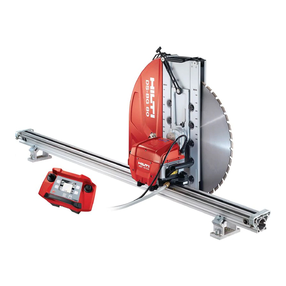
Description Product overview Saw head Toolbox Remote control unit Saw blade § Transport trolley Inner flange (saw blade: normal cutting) Blade guard center section Outer flange (saw blade: normal Guide track & cutting and dry cutting) Blade guard side section with clamping screw M12×25 10.9 Accessories box English... -
Page 17: Intended Use
• Overhead work is permissible only when additional safety measures are implemented. No-one is permitted underneath the saw when overhead work is undertaken. • Before carrying out work, consult your Hilti sales adviser. • Up to a maximum saw blade diameter of 650 mm, with the accessories for dry cutting the saw can also be used for dry-cutting masonry and lightly reinforced concrete. -
Page 18: Accessories
Qty. Designation Qty. Designation 3× eccentric pin 1× flush-cutting flange 1× Standard flange Accessories Accessories for the rail system Item number Designation Description 284808 DS-R100-L guide rail Saw head guide, long 100 cm 284809 DS-R200-L guide rail Saw head guide, long 200 cm 284810 DS-R230-L guide rail... -
Page 19: Technical Data
Item number Designation Description 2330128 DST-CF 60 6kt -45 Normal-cutting flange 2330129 DST-CF 1 3/8'' Normal-cutting flange (USA ver- sion) 221343 Hex screw M12×25 10.9 Clamping screw (inner flange, normal cut) Accessories for dry cutting Item number Designation Description 2328064 DST-CF 60 6kt -45 Dry-cutting flange 2330151... -
Page 20: Saw Blade
The noise pressure level can be reduced by approx. 10 dB(A) when noise-reducing (silent) saw blades are used. DST 10-CA Sound power level (L 114.5 dB(A) Sound pressure level (L 96.9 dB(A) -
Page 21: Overcut Or Uncut Distances
The illustration shows an example of the cutting sequence for a door opening with a dividing cut ▶ Secure the parts to be cut away so that they cannot move. Movement of the parts being cut can cause the saw blade to jam, presenting a risk of injury! Overcut or uncut distances a [mm] with saw blade diameter (⌀) - Page 22 a [mm] 240 mm 209 mm 175 mm 138 mm 117 mm 101 mm 81 mm 250 mm 242 mm 194 mm 151 mm 126 mm 109 mm 87 mm 260 mm 322 mm 217 mm 164 mm 136 mm 118 mm 94 mm 270 mm...
-
Page 23: Distance Between Rail Supports
Distance between rail supports ▶ The maximum permissible distance between rail supports, as shown in the illustration, must be observed. Position of holes drilled for fastening the rail supports Distance between anchors with Distance between track supports track support positioned on the with support positioned on the inside = 235 mm outside = 139 mm... -
Page 24: Power Source
Power source WARNING Risk of electric shock! Severe injury and burns can result if any attempt is made to operate the tool without an earth/ground conductor and ground fault circuit interrupter correctly connected. ▶ Irrespective of whether mains power or generator power is used, always make sure that an earth/ground conductor and ground fault circuit interrupter are present in the power supply and that these are correctly connected. -
Page 25: Cooling Water Supply
HKD–D M12 flush anchor is not suitable for use in masonry, man-made or natural stone and similar materials. ▶ Please contact Hilti Technical Service if you have any questions about secure fastening. The following instructions apply to use of the HKD–D M12 flush anchor. If you use a different type of anchor, please follow the anchor manufacturer’s instructions. -
Page 26: Fastening The Rail Supports
Fastening the rail supports Securing screw with collar nut Leveling screw Rail support 1. Turn back the two leveling screws until they no longer project. 2. Place the rail support over the fastening bolt. 3. Align the rail support at right angles to the line of cut and then tighten the collar nut slightly. -
Page 27: Mounting Track On Track Supports For Bevel Cutting And Adjusting Cutting
6. Fit end stops at the ends of the rail. Mounting track on track supports for bevel cutting and adjusting cutting angle 1. Slacken the clamping screw for the clamp- ing plate on all track supports. 2. Slacken the bottom clamping screw for the bevel-cut angle. - Page 28 Dimensions for setting up for angular cutting with blade diameter 660 mm 710 mm 810 mm 910 mm α 1,010 mm 1,210 mm 0° 232 mm 258 mm 283 mm 333 mm 383 mm 433 mm 533 mm 5° 239 mm 231 mm 256 mm 306 mm 356 mm...
-
Page 29: Mounting The Rail On The Rail Supports For Cutting On Stairs
Mounting the rail on the rail supports for cutting on stairs 1. Mount the rail supports for cutting on stairs on the stairs. 2. Attach the clamping insert for cutting on stairs to the rail support. 3. Slacken the clamping bolts for angle ad- justment. -
Page 30: Installing The Rail And Flush-Cutting Saw Head
Installing the rail and flush-cutting saw head ▶ When installing, make sure that the saw blade does not come into contact with the material, as otherwise friction losses would reduce the saw's performance. ▶ Allow approx. 5 mm of extra clearance between saw blade and material, or use the leveling screws rail support to set the saw to a slight angle. -
Page 31: Preparing The Saw System For Use
Preparing the saw system for use Mounting the saw head CAUTION Risk of injury! Inadvertent starting of the product. ▶ Unplug the supply cord before making adjustments to the power tool or before changing accessories. WARNING Risk of personal injury and damage to the equipment or other property! The saw presents a hazard if it falls. -
Page 32: Connecting The Saw To The Electric Supply And Water Supply
4. Before releasing your grip: Check that the guide rollers are positioned correctly and that the locking lever is fully engaged. Move the locking lever back and forth to check that engagement is correct. Connecting the saw to the electric supply and water supply Electric supply cable Mark for determining position §... -
Page 33: Adjusting The Blade Guard
3. Switch the remote control unit on. For details, please refer to the operating instructions for the DST WRC–CA remote control unit 4. Connect the cooling water hose: (Gardena system connector on the saw head). Adjusting the blade guard Blade guard holder Lever, keyless locking system 1. -
Page 34: Installing Inner Flange (Normal Cut)
▶ Check the O-ring on the inner flange for wear and damage. ▶ Before operating the saw, check the saw blade for damage (e.g. cracks, wear at the area of the flange or blue discoloration caused by overheating). Mount the saw blade in the correct direction of rotation. -
Page 35: Installing Saw Blade (Normal Cut)
Before starting installation, switch the wall saw off at the on/off switch or press the EMERGENCY STOP button. Disconnect the supply cord plug from the power outlet. Always use the genuine Hilti M12×25 10.9 clamping screw to secure the saw blade. 2328079 English... -
Page 36: Installing Inner Flange (Flush Cutting)
1. Fit the saw blade on to the centering device on the flange. ▶ The direction-of-rotation arrow on the saw blade (1) must point in the same direction as the direction-of-rotation arrow on the blade guard holder. 2. Position the outer flange on the centering spigot and screw in the clamping screw (2) . 3. -
Page 37: Installing Saw Blade (Flush-Cut)
Shouldered guide stud Saw arm arbor § 1. Remove the inner flange (normal cutting), if fitted. → page 39 2. Press the flange nut fully into the inner flange. The inside face of the flange must form a flat surface. Install the flange only if the flange nut is fully countersunk. - Page 38 1. Turn the blade guard holder in the direction from which you want to insert the saw blade with inner flange. Turn the blade guard holder so that the saw blade is held by the shouldered guide studs. 2. Push the saw blade with installed inner flange into the mount of the 6 shouldered guide studs (1).
-
Page 39: Fitting The Blade Guard
Fitting the blade guard Blade guard center section Blade guard holder & Blade guard side parts Guide wheels Clamp Tensioning lug Metal hook Rubber tensioning strap DANGER Risk of injury! Operating the saw without the blade guard fitted increases the risk of injury. ▶... -
Page 40: Working With The Saw
Working with the saw Checks before beginning sawing work WARNING Risk of injury! Using damaged parts or parts that do not function as described is highly dangerous. ▶ Do not used parts that evince signs of damage or that are not in full working order. ▶... -
Page 41: Dry-Cutting Application
▶ When making the guide cut, the power of the saw should be reduced in order to ensure a straight cut. Technical data Power setting for the guide cut ≈ 60 % Subsequent cuts Subsequent cuts can be made at full power (100 %) with the saw arm in the trailing or leading position. -
Page 42: Installing Water Bypass
8.3.2 Installing water bypass 1. Remove the screw plug from the water bypass connection (1). 2. Screw the water-connection adapter into the water bypass connection (2). 3. Use a ring/open-ended wrench to tighten the water-connection adapter hand-tight (3). 4. Connect the water drain hose to the water-connection adapter (4). 8.3.3 Installing blade guard and dust extractor 1. -
Page 43: Removing Inner Flange (Normal Cutting, Dry Cutting)
Removing inner flange (normal cutting, dry cutting) You can leave the inner flange for normal cutting installed until you are going to make a flush cut or a dry cut. The inner flange does not necessarily have to be removed for transport purposes. The carrier tool for saw blades with inner flange (flush cutting) supplied with the equipment has a hex socket that you can use to counter-hold the tie rod in the inner flange. -
Page 44: Blowing Out The Cooling Circuit
5. Blow out the cooling circuit. → page 40 6. Remove the saw head from the track. 7. Remove the guide track. 8. Dismantle / remove the track supports. 9. Clean all components and check them for damage. 10.Stow the components on the transport trolley and secure them all in position. Blowing out the cooling circuit To avoid frost damage when there is a risk of frost, the cooling circuit must be blown out after completion of the work or before long pause between periods of work. -
Page 45: Adjusting The Guide Rollers
5. Adjust the second roller in the same way. 10.2 Inspection ▶ Have the machine checked by Hilti Service at intervals of 200 operating hours. The remote control unit shows the number of operating hours remaining until the next service is due. -
Page 46: Maintenance
▶ Do not start the wall saw if you find damage and/or malfunctions. Have the wall saw repaired by Hilti Service right away. To help ensure safe and reliable operation, use only genuine Hilti spare parts and consumables. Spare parts, consumables and accessories approved by Hilti for use with your product can be found at your Hilti Store or online at: www.hilti.group... -
Page 47: Transport And Storage
Parts Procedure Daily Weekly Saw head Clean the external splines on the flange nut ✓ and the internal splines on the arbor, check condition and if damage is found have the damaged parts replaced. Check the freedom of movement of tie rod and ✓... -
Page 48: Troubleshooting
▶ Check the machine for damage before use after long periods of transport or storage. Troubleshooting If the trouble you are experiencing is not listed in this table or you are unable to rectify the problem by yourself, please contact Hilti Service. Trouble or fault Possible cause... - Page 49 Most of the materials from which Hilti products are manufactured can be recycled. The materials must be correctly separated before they can be recycled. In many countries, your old tools, machines or appliances can be returned to Hilti for recycling. Ask Hilti Service or your Hilti sales representative for further information.
- Page 50 7) by adding an acidic neutralizing agent or dilute it by adding a large quantity of water before allowing it to enter the sewerage system. Manufacturer’s warranty ▶ Please contact your local Hilti representative if you have questions about the warranty conditions. English...
- Page 52 *2328079* 2328079 Hilti = registered trademark of Hilti Corp., Schaan 20220613...
Need help?
Do you have a question about the DST 10-CA and is the answer not in the manual?
Questions and answers
HOW TO RESET WALL SAW DST 10-CA