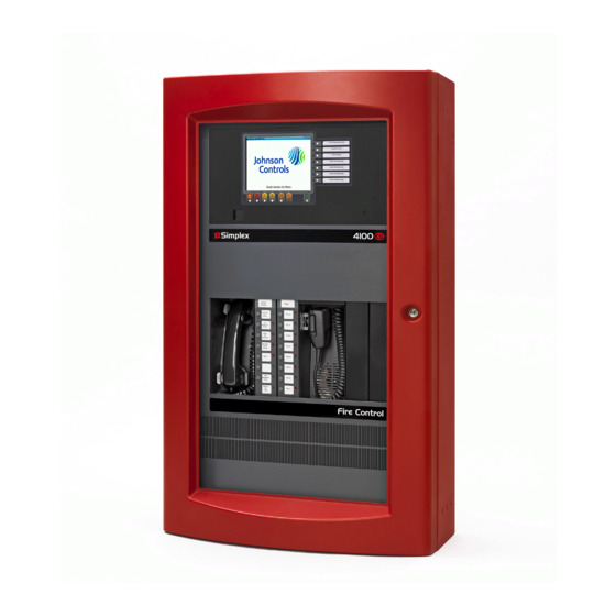
Simplex 4100 Series Installation Instructions Manual
Digital alarm communications transmitters
Hide thumbs
Also See for 4100 Series:
- Manual (60 pages) ,
- Installation instruction (33 pages) ,
- Installation instructions manual (32 pages)
Table of Contents
Advertisement
4100/4120 Series Digital Alarm Communications Transmitters Installation Instructions
Cautions, warnings, and regulatory information
READ AND SAVE THESE INSTRUCTIONS Follow the instructions in this installation manual. These instructions must be followed to avoid damage to
this product and associated equipment. Product operation and reliability depend upon proper installation.
DO NOT INSTALL ANY SIMPLEX™ PRODUCT THAT APPEARS DAMAGED Upon unpacking your Simplex product, inspect the contents
of the carton for shipping damage. If damage is apparent, immediately file a claim with the carrier and notify an authorized Simplex
product supplier.
ELECTRICAL HAZARD Disconnect electrical field power when making any internal adjustments or repairs. All repairs should be
performed by a representative or an authorized agent of your local Simplex product supplier.
STATIC HAZARD Static electricity can damage components. Handle as follows:
• Ground yourself before opening or installing components.
• Prior to installation, keep components wrapped in anti-static material at all times.
FCC RULES AND REGULATIONS – PART 15. This equipment has been tested and found to comply with the limits for a Class A digital device,
pursuant to Part 15 of the FCC Rules. These limits are designed to provide reasonable protection against harmful interference when the equipment
is operated in a commercial environment. This equipment generates, uses, and can radiate radio frequency energy and, if not installed and used in
accordance with the instruction manual, may cause harmful interference to radio communications. Operation of this equipment in a residential area is
likely to cause harmful interference in which case the user will be required to correct the interference at his own expense.
Introduction
This publication describes the installation procedure for the following:
• 4100-0155/4120-0155 Serial Digital Alarm Communications Transmitter (DACT) (non-4100U/4100ES)
• 4100-6052 DACT (4100U/4100ES)
• 4100-6080 DACT, Side Mount (4100U/4100ES)
Related Documentation
• Field Wiring Diagram for 4100 Power Limited (841-731) or,
• Field Wiring Diagram for 4100 Non Power Limited (841-995)
• 4100ES Fire Alarm System Installation Guide (574-848)
• T-Link TL250/TL300 Network Internet Alarm Communicator #29034631
• C900V2 Installation Guide Dialer Capture Ethernet Module # F01U003472-02
574-836 Rev. R
*0574836R*
Advertisement
Table of Contents

Subscribe to Our Youtube Channel
Related Manuals for Simplex 4100 Series


Summary of Contents for Simplex 4100 Series
- Page 1 DO NOT INSTALL ANY SIMPLEX™ PRODUCT THAT APPEARS DAMAGED Upon unpacking your Simplex product, inspect the contents of the carton for shipping damage. If damage is apparent, immediately file a claim with the carrier and notify an authorized Simplex product supplier.
- Page 2 4100/4120 Series Digital Alarm Communications Transmitters Installation Instructions Introduction Digital Alarm Communications Transmitter’s (DACT) are option cards that mount within 4100 Fire Alarm Control Panels (FACP). The 4100-0155/4120-0155 Serial DACT,can be programmed to notify the central station when specified events occur, or to report changes to a specific point’s status.
- Page 3 4100/4120 Series Digital Alarm Communications Transmitters Installation Instructions Figure 1: Serial DACT card 566-787 page 3 574-836 Rev. R...
-
Page 4: Specifications
4100/4120 Series Digital Alarm Communications Transmitters Installation Instructions LEDs Refer to Table 1 for DACT LED indicators. Table 1: LED Indications Possible State Power (LED 1) Not Illuminated. The system is not receiving DC power, or the power-up self-test failed. On Steady. -
Page 5: Power-Limited Wiring
The connection to the RJ-31X jacks must be made via the modular jack in installations where the DACT will share the telephone line with premises phones or other equipment. Use two Simplex harnesses for this connection - 2080-9047 (14 feet). -
Page 6: Setting The Address
4100/4120 Series Digital Alarm Communications Transmitters Installation Instructions Figure 3: Telephone system connection (each line) Configuring the DACT Configuring the DACT consists of: • Setting the correct communication mode • Specifying whether the DACT is in Test mode • Specifying whether the DACT should be ready to download new programming data •... - Page 7 4100/4120 Series Digital Alarm Communications Transmitters Installation Instructions Figure 5: DACT card switch settings page 7 574-836 Rev. R...
- Page 8 4100/4120 Series Digital Alarm Communications Transmitters Installation Instructions Data and Power Wiring Wiring Guidelines Review the following guidelines before wiring P1 and P4 of the DACT. • If U.T. motherboard 565-274 or 565-213 is wired to the DACT, jumper P4 on the motherboard must be at position 13. •...
- Page 9 4100/4120 Series Digital Alarm Communications Transmitters Installation Instructions Bootloader Switch (SW5). The bootloader switch should be left in the off position for SDACT operation. If necessary, It can be used to allow a field upgrade to the SDACT firmware. Instructions for using the bootloader will be included with any required firmware upgrades. (See Technical Support web site for future availability.) page 9 574-836 Rev.
- Page 10 4100/4120 Series Digital Alarm Communications Transmitters Installation Instructions Wiring the DACT to the TL300 Wire the DACT to the TL300 in accordance with and Figure 8. Figure 7: Wiring to the DACT to the TL300 Note: Panel containing the TL300 to be mounted within 20 feet of the FACP and mounted in the same room. The wiring to the FACP to be in conduit.
- Page 11 4100/4120 Series Digital Alarm Communications Transmitters Installation Instructions Connect to FACP, Relay N.O. contact. Relay programmed to energize when there is a telephone Line 1 or 2 trouble in the Serial DACT. To Auxiliary Power terminals 24V and 0V of the FACP SPS. MAPNET/IDNET (See 574-331).
- Page 12 4100/4120 Series Digital Alarm Communications Transmitters Installation Instructions Mounting Overview Both assemblies are designed for different systems. • The 4100-0155/4120-0155 Serial DACT mounts into a non-4100ES system (with 2975-91xx Back Boxes). • The 4100-6052 DACT and the 4100-6080 DACT can each be mounted into a 4100ES systems (with 2975-94xx Back Boxes). This section describes how to mount the cards into both types of bays.
- Page 13 4100/4120 Series Digital Alarm Communications Transmitters Installation Instructions Mounting DACT 4100-6052 Note: 4100-6052 DACT Module Figure 10: Mounting the 4100-6052 DACT module The 4100-6052 DACT should be mounted into slot 1 in a Master Controller bay. In a Non- Network systems, it can be can mounted in any open 2” slot. See Figure 10.
-
Page 14: Additional Programming
4100/4120 Series Digital Alarm Communications Transmitters Installation Instructions Mounting DACT 4100-6080 (Side Mount) Note: 4100-6080 Figure 11: Mounting the 4100-6080 DACT The 4100-6080 DACT mounts to the left side of the CPU bay end support or to the left side of any expansion bay. See Figure 11. Disconnect AC power at the source. - Page 15 4100/4120 Series Digital Alarm Communications Transmitters Installation Instructions TL300 Programming Refer to T-Link TL250/TL300 Network Internet Alarm Communicator #29034631 for information concerning the programming of the TL300. In addition to the required programming in the manual for the ULC compliance: •...
- Page 16 © 2020 Johnson Controls. All rights reserved. All specifications and other information shown were current as of document revision and are subject to change without notice. Additional listings may be applicable, contact your local Simplex® product supplier for the latest status. Listings and approvals under Simplex Time Recorder Co. Simplex, and the product names listed in this material are marks and/or registered marks. Unauthorized use is strictly prohibited. NFPA 72 and National Fire Alarm Code are registered trademarks of the National Fire Protection Association (NFPA).
Need help?
Do you have a question about the 4100 Series and is the answer not in the manual?
Questions and answers