
Related Manuals for CD Automation REVO PC M-RPC


Summary of Contents for CD Automation REVO PC M-RPC
- Page 1 USER’S MANUAL Rev. 10/2021 M-RPC CD Automation S.r.l. Via Picasso, 34/36 - 20025 Legnano (MI)- Italy Tel. +39 0331 577479 - Fax +39 0331 579479 E-mail: info@cdautomation.com - Web: www.cdautomation.com...
-
Page 3: Declaration Of Conformity
Declaration of conformity Declaration of conformity-Dichiarazione di Conformità PRODUCT MANUFACTURER/ PRODUTTORE: CD Automation S.R.L. Controllers, Drives & Automation Via Picasso, 34/36 - 20025 Legnano (MI)- Italy P.I. 08925720156 -Tel. +39 0331 577479 - Fax +39 0331 579479 E-mail: info@cdautomation.com - Web: www.cdautomation.com... -
Page 4: Important Warnings For Safety
User’s manual REVO PC Important warnings for safety This chapter contains important information for the safety. The not observance of these instructions may result in serious personal injury or death and can cause serious damages to the Thyristor unit and to the components system included. - Page 5 User’s manual REVO PC WARNING! All service including inspection, installation, wiring, maintenance, troubleshooting, fuse or other user serviceable component replacement must be performed only by properly qualified personnel. Service personnel must read this manual before proceeding with work. While service is being performed unqualified personnel should not work on the unit or be allowed in the immediate vicinity.
- Page 6 User’s manual REVO PC AVERTISSEMENT! Au moment de relever des mesures de tension ou de courant en direct, utiliser un équipement de protection individuelle approprié pour les tensions et les potentiels d’arc électrique concernés. WARNING! Verify the voltage and current ratings of the power controller are correct for the application. AVERTISSEMENT! Vérifier que les valeurs de tension et de courant du régulateur de puissance sont correctes pour l’application.
-
Page 7: Maintenance
User’s manual REVO PC Maintenance In order to have a corrected cooling, the user must clean the heat-sink and the protective grill of the fans. The frequency of this servicing depends on environmental pollution. Also check periodically if the screw for the power cables and safety earth are tightened correctly (See Connection Diagram) Warranty condition Producer gives a 12 months warranty to its products. -
Page 8: Table Of Contents
User’s manual REVO PC Summary Declaration of conformity ......3 Important warnings for safety ......4 Maintenance . - Page 9 User’s manual REVO PC 5.9 Revo PC 424 details ....... . 32 5.10 Revo PC2 details .
-
Page 10: Introduction
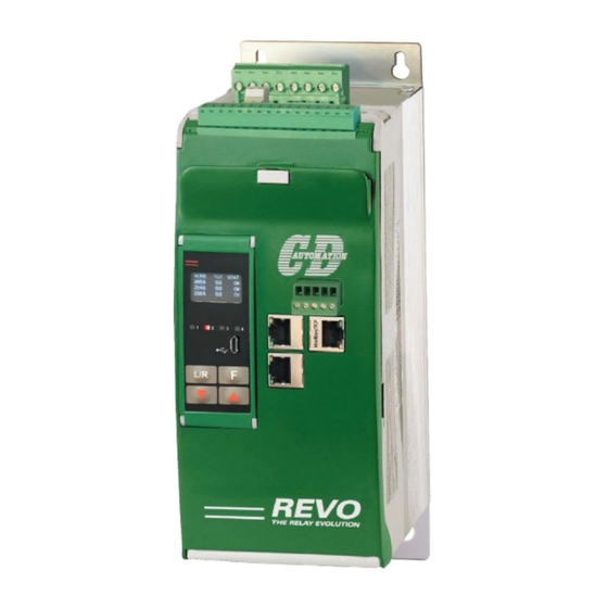
User’s manual REVO PC Introduction The REVO PC unit is designed to handle applications with multiple zones. his enhanced unit, thanks to a particular algorithm, minimizes your energy costs through the synchronization and the power limit for each zone. Revo PC keeps your instantaneous power within the limits of your electricity supply contract. REVO PC Power Controller Created specifically for industrial multi-zone applications, REVO PC can be configured to control up to 24 channels/zones. -
Page 11: Synchronization
User’s manual REVO PC 1.2 Synchronization On all controlled zones, the Live Predictive Synchronization is automatic resulting in superior performance: • Total current is equal to a sinusoidal wave form. • Power factor > 0,9. • Instantaneous current close to average value. •... -
Page 12: Revo Pc Power Controller
User’s manual REVO PC 1.4 REVO PC Power Controller REVO PC System is based on an intelligent unit that manages one or more basic SCR power controller. All currents are measured with an external current transformer. REVO PC acquires the power setpoint from different sources including: single or multi zone temperature controller, PLC or HMI. - Page 13 User’s manual REVO PC REVO PC2 Example Control Unit • REVO PC2 to control 8 load three phase with control on 2 phase (2PH) with 8 channel • Current transformer input to detect all the current • This unit transform a simple SCR Power Switch into an Intelligent Unit able to communicate and to detect load failure or short circuit...
-
Page 14: Identification And Order Code
User’s manual REVO PC Identification and order code 2.1 Identification of the unit Caution: Before to install, make sure that the Thyristor unit have not damages. If the product has a fault, please contact the dealer from which you purchased the product. The identification’s label give all the information regarding the factory settings of the unit, this label is on the unit, like represented in figure. -
Page 15: Order Code
User’s manual REVO PC 2.2 Order Code RPC612 / RPC624 - up to 24 1PH channel shared on the three phases - Connection Phase to Phase REVO PC612 / RPC624 ORDER CODE CONNECTION Firing description code description code F1-F2; F2-F3; F1-F3 All the 1PH channel can be balanced on the three Half Cycle at 50% power demand phases - Phase to Phase One Cycle at 50% power demand... - Page 16 User’s manual REVO PC RPC412 / RPC424 - up to 24 1PH channel balanced on the three phases - Connection Phase to Neutral REVO PC412 / RPC424 ORDER CODE CONNECTION Firing description code description code F1-N; F2-N; F3-N All the 1PH channel can be balanced on the three Half Cycle at 50% power demand phases - Phase to Neutral One Cycle at 50% power demand...
- Page 17 User’s manual REVO PC RPC2 - Star without Neutral or Close Delta Connection REVO S 300-800A N° 2 integrated CT N° 1 external CT REVO PC 208 Triangle or star ORDERING CODE CHANNELS FEED BACK (Control Mode) description code description code REVO-PC to drive N°4 of 3 Phase Loads with two legs (2PH) No Feed Back...
- Page 18 User’s manual REVO PC RPC3 - Star + Neutral REVO S 300-800A N° 3 integrated CT REVO PC 308 ORDERING CODE CHANNELS FEED BACK (Control Mode) description code description code REVO-PC to drive N°4 of 3 Phase Loads with three legs (3PH) No Feed Back N°12 SSR output to drive N°12 REVO S 1PH Power...
-
Page 19: Technical Specifications
User’s manual REVO PC Technical Specifications 3.1 General features Cover and Socket material: PolymericV2 IP Code: Delay switch ON/OFF time: 1/2 Period Max Auxiliary voltage, Control Circuit: 24Vdc Configurable relay output 0.5A a 24Vac/dc 3.2 Input features Digital input: 7 ÷ 30Vdc 9mA Max (ON >7Vdc OFF <6Vdc) Current Transformer Input: max 200mA Synchronization signal L1-L2-L3-N... -
Page 20: Installation
User’s manual REVO PC Installation 4.1 Dimensions and Weight 4.2 Fixing holes W (mm): D (mm): H (mm): Weight (Kg): 4.3 External Current Sensor dimensions 50/0,05A 100/0,05A - 250/0,05A 6 mm 18 mm 9 mm 6 mm 27 mm 9 mm 40 mm 40 mm 37 mm... -
Page 21: Wiring Instruction
User’s manual REVO PC Wiring instruction The Thyristor unit could be susceptible to interferences lost by near equipments or by the power supply, for this reason in accord to the fundamental practices rules is opportune take some precautions: • The coil contactor, the relays and other inductive loads must be equipped with opportune RC filter. •... -
Page 22: Command Terminals
User’s manual REVO PC 5.1 Command terminals Warning: Before connecting or disconnecting the unit check that power and control cables are isolated from voltage sources. Terminal Block MC1 Terminal MC1 Description +24Vdc AUX Voltage GND 0Vdc - Common Digital Input + Digital Input 1 (Enable) + Digital Input 2 + Digital Input 3... -
Page 23: Master Revo Pc Connection Diagram
User’s manual REVO PC 5.2 Master Revo PC Connection Diagram Caution: this procedure must be performed only by qualified persons. L1(R) L2(S) L3(T) Wire section: 1mm Fuse 0,5A 1 2 3 4 5 6 7 8 OUT 12V 30mA max OUT 1 2 3 4 5 6 7 8 10 11 12 13 14 15 16 RS485... -
Page 24: Thyristor Unit Interface
User’s manual REVO PC 5.3 Thyristor unit interface M1: Main Line supply Synchronization signal M2, M3, M4: Current transducer input M5, M6, M7: SSR output to thyristor unit MCV-1.5/12-G-3.81 M5-1 +24V M5-2 ISO1 OUT1 M5-3 270R-1%.. OUT1 M5-4 4K7-1%... 270R-1%.. KPTR-3216CGCK TLP187 ISO2... -
Page 25: Digital 0Utput
User’s manual REVO PC 5.4 Digital 0utput Terminal Block M5-M6-M7: SSR output to thyristor unit Terminal M5 Description (Phase 1) To the of all SSR of Phase 1, in parallel +24Vdc Com Digital Output + Digital Output 1 + Digital Output 2 + Digital Output 3 To all individual + Digital Output 4... - Page 26 User’s manual REVO PC Wiring connection L2/N L2/N M2-M3-M4 H.B. H.B. H.B. H.B. H.B. H.B. H.B. H.B. S.C. S.C. S.C. S.C. S.C. S.C. S.C. S.C. M5-M6-M7 +Digital Out 8/16/24 +Digital Out 7/15/23 +Digital Out 6/14/22 +Digital Out 5/13/21 +Digital Out 4/12/20 +Digital Out 3/11/19 +Digital Out 2/10/18 +Digital Out 1/9/17...
- Page 27 User’s manual REVO PC Recommended cable: 035 mm - AWG 22 Recommended cable: 1 mm...
-
Page 28: Analog Current Transformer Input
User’s manual REVO PC 5.5 Analog current transformer input Terminal Block M2-M3-M4 max 200mA Terminal M2 Description Terminal M3 Description Current transformer input Channel 1 Current transformer input Channel 9 Current transformer input Channel 2 CT10 Current transformer input Channel 10 Current transformer input Channel 3 CT11 Current transformer input Channel 11... -
Page 29: Revo Pc 612 Details
User’s manual REVO PC 5.6 Revo PC 612 details Up to 12 1PH channel shared on the three phases. Connection Phase to Phase. Channel 1 on phase L1 Channel 1 on phase L2 Ch17 Channel 1 on phase L3 Channel 2 on phase L1 Channel 2 on phase L2 Channel 2 on phase L3 Ch10... -
Page 30: Revo Pc 624 Details
User’s manual REVO PC 5.7 Revo PC 624 details Up to 24 1PH channel shared on the three phases. Connection Phase to Phase. Channel 1 on phase L1 Channel 1 on phase L2 Ch17 Channel 1 on phase L3 Channel 2 on phase L1 Channel 2 on phase L2 Channel 2 on phase L3 Ch10... -
Page 31: Revo Pc 412 Details
User’s manual REVO PC 5.8 Revo PC 412 details Up to 12 1PH channel balanced on the three phases. Connection Phase to Neutral. Channel 1 on phase L1 Channel 1 on phase L2 Ch17 Channel 1 on phase L3 Channel 2 on phase L1 Channel 2 on phase L2 Channel 2 on phase L3 Ch10... -
Page 32: Revo Pc 424 Details
User’s manual REVO PC 5.9 Revo PC 424 details Up to 24 1PH channel balanced on the three phases. Connection Phase to Neutral. Channel 1 on phase L1 Channel 1 on phase L2 Ch17 Channel 1 on phase L3 Channel 2 on phase L1 Channel 2 on phase L2 Channel 2 on phase L3 Ch10... -
Page 33: Revo Pc2 Details
User’s manual REVO PC 5.10 Revo PC2 details On REVO PC2 is possible to control 8 LOAD Three phase with control on two phase (2PH) with 8 Channel. Channel 1 on phase L1 Ch17 Channel 1 on phase L3 Channel 2 on phase L1 Channel 2 on phase L3 Ch18 Channel 3 on phase L1... -
Page 34: Revo Pc3 Details
User’s manual REVO PC 5.11 Revo PC3 details On REVO PC3 is possible to control 8 LOAD Three phase with control on three phase(3PH) with 8 Channel. Channel 1 on phase L1 Channel 1 on phase L2 Ch17 Channel 1 on phase L3 Channel 2 on phase L1 Channel 2 on phase L2 Channel 2 on phase L3... -
Page 35: Control Panel
User’s manual REVO PC Control Panel The Control Panel is placed on the front of the unit, on its display you can visualize the alarms, the input and output signals and all the configuration parameters. The Control Panel is composed by 4 pushbutton appropriately identified: based on the state of the device each button assumes a specific function, as described below. -
Page 36: Display
User’s manual REVO PC 6.1 Display All ON Heasink LED 1 over temperature Flashing: the unit wait “enable” LED 4 command Flashing: Fixed: “enable” command Thermal alarm Fixed: Heater Break or Short Circuit or Current Limit or Comm WatchDog LED 2 alarm Flashing ratio LED 3... -
Page 37: Displayed Parameters
User’s manual REVO PC 6.2 Displayed parameters Press Shows status, voltage line and total power for each stage VLine Status 321.0 231.1 227.9 Press Shows heat sink temperature and line frequency for each stage V FREQ TEMP 33.2°C 49.98Hz 35.4°C 49.98Hz 49.98Hz 34.0°C... -
Page 38: Configurator Software
User’s manual REVO PC Configurator software CDA Thyristor configurator software is available to download from our site free of charge. You can download it here: https:/ /www.cdautomation.com/download/cd-automation/software/ThyristorConfigurator_ver6.exe The following features are available starting from version 5.8.0.1. NOTE: we recommend to download the latest version. To install the software, launch the downloaded program and follow the instructions on the screen. -
Page 39: Test View Main Page
User’s manual REVO PC 7.2 Test View main page This page can be used to monitor and adjust the operation of the REVO PC while communicating with it in real time. Main features available are: • Enable zones • Select the source for Power Set Point •... - Page 40 User’s manual REVO PC 7.2.1 Unit Load setting To operate optimally the REVO PC unit needs some settings to align the unit to the piloted load. To send the Power Load data from the configurator it is necessary to flag “Set Load Data” clicking with right mouse button on Load (V) column.
- Page 41 User’s manual REVO PC REVO PC Example How to set a system (connection phase to phase) of 21 channel with REVO PC, shared on the three phases. L1-L2 Channel 1: 8 kW Channel 2: 10 kW Channel 3: 10 kW Channel 4: 8 kW Channel 5: 10 kW Channel 6: 10 kW...
- Page 42 User’s manual REVO PC 7.2.2 User Access level To limit unauthorized access to Revo PC configuration, security passwords are required to log in click on “Actual Level “ label Will appear the login window Insert the password click on “OK” button. The levels description is: Level Password...
- Page 43 User’s manual REVO PC 7.2.4 I/O Config menu There are N°4 Digital Input and a N°1 Digital Output available on the main module, each one can be associated to a specific function. Digital Output menu 1 = Set the Digital Output function •...
- Page 44 User’s manual REVO PC 7.2.6 System menu System Configurations Alarms enable = Enable diagnostic alarms (HB or S.C.) • H.B. Heater Break • S.C. Short Circuit HB Sense (%) = Set the threshold of resistance that activates the Heater Break alarm. This setting is in percentage of the nominal load resistance HB Delay (sec) = activation delay of heart break Thermal alarm Set Point = Set the threshold of...
-
Page 45: Alarm Description
User’s manual REVO PC Alarm description 8.1 Heater Break Alarm This option allows you to diagnose any load breakage. The diagnostics is based on the comparison of the value of the nominal resistance of the load with respect to the resistance measured in real time. The nominal resistance is calculated using the Operative Load Voltage (Load V) and Load Power (Load kW) parameters. -
Page 46: Short Circuit
User’s manual REVO PC Using the HB Delay parameter, the alarm intervention can be delayed (menu System, see paragraph 7.2.2). HB delay (es: 2.5 sec.) NO ALARM HB sense (+20%) 26,4 22: R (V/I) ALARM HB delay (es: 2.5 sec.) HB sense (+20%) 26,4 22: R (V/I) -
Page 47: Communication
User’s manual REVO PC Communication Modbus/TCP communication port is available as standard. Other serial communication port are available as option. Standard Option Option Modbus/TCP Ethernet/IP Profibus Profinet... - Page 48 CD Automation S.r.l. Via Picasso, 34/36 - 20025 Legnano (MI) - Italy Tel. +39 0331 577479 - Fax +39 0331 579479 E-mail: info@cdautomation.com - Web: www.cdautomation.com...
Need help?
Do you have a question about the REVO PC M-RPC and is the answer not in the manual?
Questions and answers