Table of Contents
Advertisement
Quick Links
M39x8
M-Series 8CHs AI Modules
M3918, M3928, M3938, M3948
M3918 (8 Channels, Differential Current Input, 0~20mA / 4~20mA / -20~20mA, 12bits)
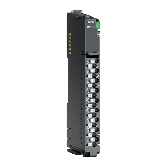
M3928 (8 Channels, Differential Voltage Input, 0~10V / 0~5V / -10~10V / -5~5V, 12bits)
M3938 (8 Channels, Differential Current Input, 0~20mA / 4~20mA / -20~20mA, 16bits)
M3948 (8 Channels, Differential Voltage Input, 0~10V / 0~5V / -10~10V / -5~5V, 16bits)
Specification
FnIO M – Series :
Revision 1.03(2020.05.07)
Page 1
Advertisement
Table of Contents

Related Manuals for CREVIS M Series


Summary of Contents for CREVIS M Series
- Page 1 M39x8 Revision 1.03(2020.05.07) Specification M-Series 8CHs AI Modules Page 1 FnIO M – Series : M3918, M3928, M3938, M3948 M3918 (8 Channels, Differential Current Input, 0~20mA / 4~20mA / -20~20mA, 12bits) M3928 (8 Channels, Differential Voltage Input, 0~10V / 0~5V / -10~10V / -5~5V, 12bits) M3938 (8 Channels, Differential Current Input, 0~20mA / 4~20mA / -20~20mA, 16bits) M3948 (8 Channels, Differential Voltage Input, 0~10V / 0~5V / -10~10V / -5~5V, 16bits)
-
Page 2: History
M39x8 Revision 1.03(2020.05.07) Specification M-Series 8CHs AI Modules Page 2 History REV. PAGES REMARKS DATE Editor Preliminary 2020/2/10 BS HA 1.01 Image, Torque, Hotswap Function 2020/04/21 CW SEO 1.02 Vibration specification, Product certification changed 2020/04/27 CW SEO 1.03 32-36 Added ATEX certificate 2020/05/07 CW SEO... -
Page 3: Table Of Contents
M39x8 Revision 1.03(2020.05.07) Specification M-Series 8CHs AI Modules Page 3 Table of Contents History ................................2 Table of Contents .............................. 3 1.Environment Specification ..........................5 2.M3918 (8 Channels, Differential Current Input, 0~20mA / 4~20mA / -20~20mA, 12bits) ......6 2.1.M3918 Specification ..........................6 2.2.M3918 Wiring Diagram .......................... - Page 4 M39x8 Revision 1.03(2020.05.07) Specification M-Series 8CHs AI Modules Page 4 6.Input Range Setting & Conversion Time Setting ..................30 6.1.M3918, M3938 ............................. 30 6.2.M3928, M3948 ............................. 30 6.3.Hot Swap Function ..........................31 6.3.1.Network Adapter ..........................31 6.3.2.Power Module ..........................31 6.3.3.IO Module ............................
-
Page 5: Environment Specification
M39x8 Revision 1.03(2020.05.07) Specification M-Series 8CHs AI Modules Page 5 1. Environment Specification Environmental specification Operating Temperature -25℃~60℃ UL Temperature -20℃~60℃ Storage Temperature -40℃~85℃ Relative Humidity 5% ~ 90% non-condensing Mounting DIN rail General specification Shock Operating IEC 60068-2-27 Vibration Resistance Based on IEC 60068-2-6 DNVGL-CG-0039 : Vibration Class B, 4g Industrial Emissions... -
Page 6: M3918 (8 Channels, Differential Current Input, 0~20Ma / 4~20Ma / -20~20Ma, 12Bits)
M39x8 Revision 1.03(2020.05.07) Specification M-Series 8CHs AI Modules Page 6 2. M3918 ( 8 Channels, Differential Current Input, 0~20mA / 4~20mA / -20~20mA, 12bits 2.1. M3918 Specification Items Specification Input Specification Inputs Per Module 8 Channels Differential, Non-isolated Between Channels Indicators 1 Green M bus Status LED 12 bits : 4.88uA/bit(0~20mA) -
Page 7: M3918 Wiring Diagram
M39x8 Revision 1.03(2020.05.07) Specification M-Series 8CHs AI Modules Page 7 2.2. M3918 Wiring Diagram Series No Through Air Over Surface Signal Description Pin No. RTB18C 1.5mm 1.5mm 175≤CTI≤400 Input Channel 0(+) Spacings : The follwing minimum spcing in inches(millimeters) shall be Input Channel 0(-) maintained between uninsulated live parts of opposite polarity;... -
Page 8: M3918 Led Indicator
M39x8 Revision 1.03(2020.05.07) Specification M-Series 8CHs AI Modules Page 8 2.3. M3918 LED Indicator 2.3.1. LED Indicator LED No. LED Function / Description LED Color STATUS M bus Status Green 2.3.2. Channel Status LED Status To indicate Disconnection M-bus Status Green Connection... -
Page 9: Data Value / Current
M39x8 Revision 1.03(2020.05.07) Specification M-Series 8CHs AI Modules Page 9 2.4. Data Value / Current Current Range : 0~20mA Current 0.0mA 5.0mA 10.0mA 20.0mA Data(Hex) H0000 H03FF H07FF H0FFF Current Range : 4~20mA Current 4.0mA 8.0mA 12.0mA 20.0mA Data(Hex) H0000 H03FF H07FF H0FFF... - Page 10 M39x8 Revision 1.03(2020.05.07) Specification M-Series 8CHs AI Modules Page 10 Current Range : -20~20mA Current -20.0mA -10.0mA +10.0mA +20.mA Data(Hex) HF800 HFC00 H0000 H03FF H07FF...
-
Page 11: Mapping Data Into The Image Table
M39x8 Revision 1.03(2020.05.07) Specification M-Series 8CHs AI Modules Page 11 2.5. Mapping Data into the Image Table ● Input Module Data Analog Input Ch0 Analog Input Ch1 Analog Input Ch2 Analog Input Ch3 Analog Input Ch4 Analog Input Ch5 Analog Input Ch6 Analog Input Ch7 ●... -
Page 12: M3928 (8 Channels, Differential Voltage Input, 0~10V / 0~5V / -10~10V / -5~5V, 12Bits)
M39x8 Revision 1.03(2020.05.07) Specification M-Series 8CHs AI Modules Page 12 3. M3928 ( 8 Channels, Differential Voltage Input, 0~10V / 0~5V / -10~10V / -5~5V, 12bits 3.1. M3928 Specification Items Specification Input Specification Inputs Per Module 8 Channels Differential, Non-isolated Between Channels Indicators 1 Green M bus Status LED 12 bits : 2.44mV/Bit(0~10V) -
Page 13: M3928 Wiring Diagram
M39x8 Revision 1.03(2020.05.07) Specification M-Series 8CHs AI Modules Page 13 3.2. M3928 Wiring Diagram Series No Through Air Over Surface Signal Description Pin No. RTB18C 1.5mm 1.5mm 175≤CTI≤400 Input Channel 0(+) Spacings : The follwing minimum spcing in inches(millimeters) shall be Input Channel 0(-) maintained between uninsulated live parts of opposite polarity;... -
Page 14: M3928 Led Indicator
M39x8 Revision 1.03(2020.05.07) Specification M-Series 8CHs AI Modules Page 14 3.3. M3928 LED Indicator 3.3.1. LED Indicator LED No. LED Function / Description LED Color STATUS M bus Status Green 3.3.2. Channel Status LED Status To indicate Disconnection M-bus Status Green Connection... -
Page 15: Data Value / Voltage
M39x8 Revision 1.03(2020.05.07) Specification M-Series 8CHs AI Modules Page 15 3.4. Data Value / Voltage Voltage Range : 0~10V Voltage 2.5V 5.0V 10.0V Data(Hex) H0000 H03FF H07FF H0FFF Voltage Range : 0~5V Current 1.25V 2.5V 5.0V Data(Hex) H0000 H03FF H07FF H0FFF... - Page 16 M39x8 Revision 1.03(2020.05.07) Specification M-Series 8CHs AI Modules Page 16 Voltage Range : -10~10V Current -10V 5.0V 10.0V Data(Hex) HF800 HFC00 H0000 H03FF H07FF Voltage Range : -5~5V Current -2.5V 2.5V 5.0V Data(Hex) HF800 HFC00 H0000 H03FF H07FF...
-
Page 17: Mapping Data Into The Image Table
M39x8 Revision 1.03(2020.05.07) Specification M-Series 8CHs AI Modules Page 17 3.5. Mapping Data into the Image Table ● Input Module Data Analog Input Ch0 Analog Input Ch1 Analog Input Ch2 Analog Input Ch3 Analog Input Ch4 Analog Input Ch5 Analog Input Ch6 Analog Input Ch7 ●... -
Page 18: M3938 (8 Channels, Differential Current Input, 0~20Ma / 4~20Ma / -20~20Ma, 16Bits)
M39x8 Revision 1.03(2020.05.07) Specification M-Series 8CHs AI Modules Page 18 4. M3938 ( 8 Channels, Differential Current Input, 0~20mA / 4~20mA / -20~20mA, 16bits 4.1. M3938 Specification Items Specification Input Specification Inputs Per Module 8 Channels Differential, Non-isolated Between Channels Indicators 1 Green M bus Status LED 16bit(Include Sign) -
Page 19: M3938 Wiring Diagram
M39x8 Revision 1.03(2020.05.07) Specification M-Series 8CHs AI Modules Page 19 4.2. M3938 Wiring Diagram Series No Through Air Over Surface Signal Description Pin No. RTB18C 1.5mm 1.5mm 175≤CTI≤400 Input Channel 0(+) Spacings : The follwing minimum spcing in inches(millimeters) shall be Input Channel 0(-) maintained between uninsulated live parts of opposite polarity;... -
Page 20: M3938 Led Indicator
M39x8 Revision 1.03(2020.05.07) Specification M-Series 8CHs AI Modules Page 20 4.3. M3938 LED Indicator 4.3.1. LED Indicator LED No. LED Function / Description LED Color STATUS Status LED Green 4.3.2. Channel Status LED Status To indicate Disconnection M-bus Status Green Connection... -
Page 21: Data Value / Current
M39x8 Revision 1.03(2020.05.07) Specification M-Series 8CHs AI Modules Page 21 4.4. Data Value / Current Current Range : 0~20mA Current 0.0mA 5.0mA 10.0mA 20.0mA Data(Hex) H0000 H1FFF H3FFF H7FFF Current Range : 4~20mA Current 4.0mA 8.0mA 12.0mA 20.0mA Data(Hex) H0000 H1FFF H3FFF H7FFF... - Page 22 M39x8 Revision 1.03(2020.05.07) Specification M-Series 8CHs AI Modules Page 22 Current Range : -20~20mA Current -20.0mA -10.0mA +10.0mA +20.mA Data(Hex) HC000 HE000 H0000 H1FFF H3FFF...
-
Page 23: Mapping Data Into The Image Table
M39x8 Revision 1.03(2020.05.07) Specification M-Series 8CHs AI Modules Page 23 4.5. Mapping Data into the Image Table ● Input Module Data Analog Input Ch0 Analog Input Ch1 Analog Input Ch2 Analog Input Ch3 Analog Input Ch4 Analog Input Ch5 Analog Input Ch6 Analog Input Ch7 ●... -
Page 24: M3948 (8 Channels, Differential Voltage Input, 0~10V / 0~5V / -10~10V / -5~5V, 16Bits)
M39x8 Revision 1.03(2020.05.07) Specification M-Series 8CHs AI Modules Page 24 5. M3948 ( 8 Channels, Differential Voltage Input, 0~10V / 0~5V / -10~10V / -5~5V, 16bits 5.1. M3948 Specification Items Specification Input Specification Inputs Per Module 8 Channels Differential, Non-isolated Between Channels Indicators 1 Green M bus Status LED 16bit(Include Sign) -
Page 25: M3948 Wiring Diagram
M39x8 Revision 1.03(2020.05.07) Specification M-Series 8CHs AI Modules Page 25 5.2. M3948 Wiring Diagram Series No Through Air Over Surface Signal Description Pin No. RTB18C 1.5mm 1.5mm 175≤CTI≤400 Input Channel 0(+) Spacings : The follwing minimum spcing in inches(millimeters) shall be Input Channel 0(-) maintained between uninsulated live parts of opposite polarity;... -
Page 26: M3948 Led Indicator
M39x8 Revision 1.03(2020.05.07) Specification M-Series 8CHs AI Modules Page 26 5.3. M3948 LED Indicator 5.3.1. LED Indicator LED No. LED Function / Description LED Color STATUS Status LED Green 5.3.2. Channel Status LED Status To indicate Disconnection M-bus Status Green Connection... -
Page 27: Data Value / Voltage
M39x8 Revision 1.03(2020.05.07) Specification M-Series 8CHs AI Modules Page 27 5.4. Data Value / Voltage Voltage Range : 0~10V Voltage 2.5V 5.0V 10.0V Data(Hex) H0000 H1FFF H3FFF H7FFF Voltage Range : 0~5V Current 1.25V 2.5V 5.0V Data(Hex) H0000 H1FFF H3FFF H7FFF... - Page 28 M39x8 Revision 1.03(2020.05.07) Specification M-Series 8CHs AI Modules Page 28 Voltage Range : -10~10V Current -10V 5.0V 10.0V Data(Hex) HC000 HE000 H0000 H1FFF H3FFF Voltage Range : -5~5V Current -2.5V 2.5V 5.0V Data(Hex) HC000 HE000 H0000 H1FFF H3FFF...
-
Page 29: Mapping Data Into The Image Table
M39x8 Revision 1.03(2020.05.07) Specification M-Series 8CHs AI Modules Page 29 5.5. Mapping Data into the Image Table ● Input Module Data Analog Input Ch0 Analog Input Ch1 Analog Input Ch2 Analog Input Ch3 Analog Input Ch4 Analog Input Ch5 Analog Input Ch6 Analog Input Ch7 ●... -
Page 30: Input Range Setting & Conversion Time Setting
M39x8 Revision 1.03(2020.05.07) Specification M-Series 8CHs AI Modules Page 30 6. Input Range Setting & Conversion Time Setting 6.1. M3918, M3938 Byte Bit 7 Bit 6 Bit 5 Bit 4 Bit 3 Bit 2 Bit 1 Bit 0 Ch#0 Command(H00 : 0~20mA, H01 : 4~20mA, H02 : -20~20mA) Ch#1 Command(H00 : 0~20mA, H01 : 4~20mA, H02 : -20~20mA) Ch#2 Command(H00 : 0~20mA, H01 : 4~20mA, H02 : -20~20mA) Ch#3 Command(H00 : 0~20mA, H01 : 4~20mA, H02 : -20~20mA) -
Page 31: Hot Swap Function
M39x8 Revision 1.03(2020.05.07) Specification M-Series 8CHs AI Modules Page 31 6.3. Hot Swap Function The M-Series has hot-swap capability to protect your system. *Caution If you remove multiple IO modules by mistake, you must connect IO modules one by one, starting with the lower slot number. -
Page 32: Fnio M-Series Caution(Before Using The Unit)
Page 32 7. FnIO M-Series Caution(Before using the unit) ■ We appreciate you for purchasing CREVIS Products. To use the units more effectively, please read this quick guide and refer to the respective user manual for further details. Cautions for your Safety If you don’t follow the directions, it could cause a personal injury, damage to the equipment or explosion. -
Page 33: Module Mounting
M39x8 Revision 1.03(2020.05.07) Specification M-Series 8CHs AI Modules Page 33 7.2. Module Mounting 7.2.1. How to mount & dismount M-Series Modules on Din-Rail 1) Ready 2) Unlock the 'Din Rail-Locker' like Number (1). 3) Push the module to the din-rail. 4) Lock the 'Din Rail-Locker' like Number (3) to fix the module on the din rail. - Page 34 M39x8 Revision 1.03(2020.05.07) Specification M-Series 8CHs AI Modules Page 34 8) End...
-
Page 35: Use In Hazardous Environments
M39x8 Revision 1.03(2020.05.07) Specification M-Series 8CHs AI Modules Page 35 8. Use in Hazardous Environments ATEX Zone2 Information 1. Certification number : DEMKO 19 ATEX 2223X 2. Ambient range (-20℃ ≤ Tamb ≤ +60℃) 3. Certification string : II 3 G Ex ec IIC T4 Gc 4. - Page 36 M39x8 Revision 1.03(2020.05.07) Specification M-Series 8CHs AI Modules Page 36 ATEX Zone22 Information...
Need help?
Do you have a question about the M Series and is the answer not in the manual?
Questions and answers