Advertisement
Table of Contents
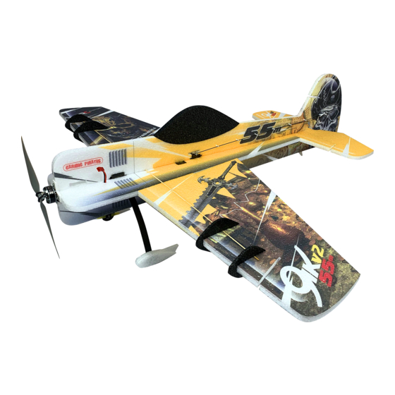
Yak 55 3D/aerobatic EPP model
Building instructions
Please refer to the Diagram sheet
Diagrams A, B
Press 2 carbon strips (3x0,5x800 mm) into the grooves in the sides of the fuselage central part (the „backbone").
Position the backbone on your workbench on its side, gently press if necessary and make sure that the sides are
perfectly straight. Apply thin CA glue over the carbon strips and saw off their overhanging ends.
Diagram C
Use thin or medium CA to attach the wing halves to the backbone. Note the little tabs that should help you
position the wing halves correctly. (put some down pressure on the thickest part of the root of the wing first to
set the wing at 0° incidence). Caution! The backbone should be in inverted position, i.e. the elevator cutout
facing down and the wings should be attached with their bottom side up! If you get this wrong, your elevator
will not fit into the fuselage correctly.
Diagram D
Locate two carbon rods of 1.5 mm diameter. Use sharp hobby knife to cut shallow (3-5mm) slits into the
upper and lower surface of the wing as indicated. Press the two carbon rods into the slits. Make sure that the
wing is perfectly straight (press gently down on the workbench) and apply thin CA glue over the carbon
strips.
Diagram E
Cut shallow slits into the elevator upper and lower surface as indicated. Press in two 120 mm carbon strips.
Make sure that the elevator is straight and apply thin CA glue over the carbon strips.
Diagram F
Glue (using thin or medium CA) the canopy (made of black EPP) into place. Use sharp hobby knife to
separate the fuselage upper and lower parts, cutting through the center of the little tabs.
Diagram G
Put the backbone on your workbench in inverted position (the stabilizer cutout is again facing down). See the
slot in the lower fuselage part to position the landing gear mount correctly on the backbone. Use thin CA to
glue the mount to the backbone.
Diagram H
Connect the lower fuselage part to the bacbone using thin or medium CA or contact glue. Install the
stab/elevator into the assembly using thin or medium CA (check its proper alignment first).
Diagram I
Drill holes into the landing gear as indicated.
Diagram J
Use the two little screws to secure the landing gear to the backbone mount. Assemble the landing gear as
indicated. Gluing the EPP wheel pants to their mounting tabs is the last step of the LG assembly.
Diagram K
Now is the convenient time to install aileron servos. Cut appropriate slots into the wing lower surface using
sharp hobby knife. Make the slot somewhat smaller, for a tight fit. Use hot glue or thick CA to install the
servos. Cut into the ailerons and press in the aileron control horns. Make sure your servos are centered (with
zero trim).
Use the included pushrods, the Z-bend goes into the control horn. You may use your favourite method to
connect the pushrods to the servo arms. Making another Z-bend is the easy solution, in such case make sure
that the aileron is in neutral position and glue the control horn into the aileron as the last step. In any case,
make sure that the hole in the control horn is approximately above the hinge center line.
Diagram L
Cut into the rear bottom part of the fuselage and install the tailskid using thin CA, as indicated. Attach the
upper fuselage part to the backbone using thin or medium CA.
Diagram M
Cut appropriate slits into the fuselage rear part and the rudder, as indicated. Install the rudder using the two
plastic hinges. Make sure that the rudder throws are sufficient and apply some thin CA glue into the hinges.
Diagram N
Assemble the motor mount as indicated. Use thin or medium CA glue or epoxy and make sure that all is glued
well.
Diagram O
Locate one toothpick. Cut it in half. Use thin or medium CA to glue the motor mount into the fuselage front.
Use the toothpick halves to pin the motor mount into the upper and lower fuselage part; glue with thin CA.
Advertisement
Table of Contents

Subscribe to Our Youtube Channel
Related Manuals for RC Factory Yak 55


Summary of Contents for RC Factory Yak 55
- Page 1 Yak 55 3D/aerobatic EPP model Building instructions Please refer to the Diagram sheet Diagrams A, B Press 2 carbon strips (3x0,5x800 mm) into the grooves in the sides of the fuselage central part (the „backbone“). Position the backbone on your workbench on its side, gently press if necessary and make sure that the sides are perfectly straight.
- Page 2 For clean rolls, without any coupling to yaw, you may want to play with aileron differential (different up and down deflection of ailerons). Have fun! Your RC Factory team. Technical specs: Wingspan 1020 mm...
Need help?
Do you have a question about the Yak 55 and is the answer not in the manual?
Questions and answers