Table of Contents
Advertisement
Quick Links
1.
Warnings
Do not look directly into the light source of the sensor.
> Risk of injury, damage to the eyes and skin
Connect the power supply and the display/output device according to the safety regula-
tions for electrical equipment.
> Risk of injury
> Damage to or destruction of the sensor
Avoid shocks and impacts to the sensor and the controller. The supply voltage must not
exceed the specified limits. Avoid constant exposure of the sensor to dust or splashes of
water by taking suitable measures such as blowing off or using a protective housing. The
sensor housing may only be opened by authorized persons.
> Damage to or destruction of the sensor and/or the controller
Do not touch the protective windows. Remove any fingerprints immediately using pure
alcohol and a clean cotton cloth without leaving any streaks. Protect the cables against
damage.
> Failure of the measuring device
Only plug in or disconnect devices when disconnected from the power supply.
2.
Notes on CE Marking
The following apply to the surfaceCONTROL 3D 25x0 measuring system:
- EU Directive 2014/30/EU
- EU Directive 2011/65/EU
Products which carry the CE mark satisfy the requirements of the EU directives cited and
the relevant applicable harmonized European standards (EN). The measuring system is
designed for use in industrial environments.
The EU Declaration of Conformity and the technical documentation are available to the
responsible authorities according to the EU Directives.
Assembly Instructions
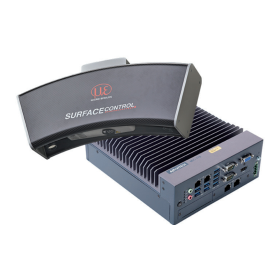
surfaceCONTROL
3D SC2500 / SC2510
Advertisement
Table of Contents

Summary of Contents for MICRO-EPSILON surfaceCONTROL 3D SC2500
- Page 1 Assembly Instructions surfaceCONTROL 3D SC2500 / SC2510 Warnings Do not look directly into the light source of the sensor. > Risk of injury, damage to the eyes and skin Connect the power supply and the display/output device according to the safety regula- tions for electrical equipment.
-
Page 2: Proper Environment
Check the delivery for completeness and shipping damage immediately after un- packing. If there is damage or parts are missing, immediately contact the manufacturer or supplier. surfaceCONTROL 3D SC2500 / SC2510 Page 2... -
Page 3: Light Source
Fig. 1 LED warning sign If the information sign is covered over when the unit is installed, the user must en- sure that a supplementary information sign is attached at the installation location. surfaceCONTROL 3D SC2500 / SC2510 Page 3... -
Page 4: Electrical Connections
The cable shield is connected to the connector housing. A 2-pin LEMO PushPull connector is used on sensor side. Only use the included table power pack for the power supply of the surfaceCON- TROL 2500 sensor. surfaceCONTROL 3D SC2500 / SC2510 Page 4... - Page 5 RJ45 connectors are used on the PC side. Use only the Ethernet cable sup- plied in the scope of delivery. Fig. 6 Connecting Ethernet connector to port Tighten the cable connector. surfaceCONTROL 3D SC2500 / SC2510 Page 5...
- Page 6 Fig. 8 Pin assignment of the power supply connection, view: plug on housing side The operating voltage is protected against polarity reversal. Use only shielded lines or original cables from the accessories program for the power supply connection or the outputs. surfaceCONTROL 3D SC2500 / SC2510 Page 6...
-
Page 7: Mounting Of The Sensor
Ensure that you can hold the sensor securely while pulling out. If necessary, have a second person assist. Ensure careful handling during installation and operation. Damage to or destruction of the sensor. surfaceCONTROL 3D SC2500 / SC2510 Page 7... -
Page 8: Operation
The Power LED on the controller is illuminated red if the power supply is sufficient, and green after pressing the Power button. It starts when the supply voltage is applied. The surfaceCONTROL 3D 25x0 sensor requires a warm-up time of typically 60 min- utes for precise measurements. surfaceCONTROL 3D SC2500 / SC2510 Page 8... -
Page 9: Operating Programs
(Link Local Address). You can now operate the surfaceCONTROL 3D 25x0 measuring system using the operat- ing programs listed above. surfaceCONTROL 3D SC2500 / SC2510 Page 9... - Page 10 Fig. 9 Result of camera images when aligned with crosshair For further details, please refer to - the respective operating instructions of the software provided by Micro-Epsilon, - or the operating instructions of this sensor in GenICam parameter description section.
- Page 11 However, should any defects occur despite careful quality control, these shall be reported immediately to MICRO-EPSILON or to your distributor / retailer. MICRO-EPSILON undertakes no liability whatsoever for damage, loss or costs caused by or related in any way to the product, in particular consequential damage, e.g., due to...
-
Page 12: Service & Repair
In the interest of further development, MICRO-EPSILON reserves the right to modify the design. In addition, the General Terms of Business of MICRO-EPSILON shall apply, which can be accessed under Legal details | Micro-Epsilon https://www.micro-epsilon.com/impressum/. For translations into other languages, the German version shall prevail.


Need help?
Do you have a question about the surfaceCONTROL 3D SC2500 and is the answer not in the manual?
Questions and answers