Table of Contents
Advertisement
Quick Links
MFA-7
MFA-14
MFA-21
MFA-28
MICRO-EPSILON Eltrotec GmbH
Manfred-Wörner-Straße 101 · 73037 Göppingen / Germany
Tel. +49 (0) 7161/98872-300 · Fax +49 (0) 7161/98872-303
eltrotec@micro-epsilon.com · www.micro-epsilon.com
Your local contact:
www.micro-epsilon.com/contact/worldwide/
Operating Instructions
colorCONTROL
MFA
Advertisement
Table of Contents

Subscribe to Our Youtube Channel
Related Manuals for MICRO-EPSILON colorCONTROL MFA


Summary of Contents for MICRO-EPSILON colorCONTROL MFA
- Page 1 Operating Instructions colorCONTROL MFA-7 MFA-14 MFA-21 MFA-28 MICRO-EPSILON Eltrotec GmbH Manfred-Wörner-Straße 101 · 73037 Göppingen / Germany Tel. +49 (0) 7161/98872-300 · Fax +49 (0) 7161/98872-303 eltrotec@micro-epsilon.com · www.micro-epsilon.com Your local contact: www.micro-epsilon.com/contact/worldwide/...
- Page 2 Sensor system for testing LED function, color and intensity MICRO-EPSILON Eltrotec GmbH Manfred-Wörner-Straße 101 73037 Göppingen / Germany Tel. +49 (0) 7161 / 98872-300 Fax +49 (0) 7161 / 98872-303 e-mail eltrotec@micro-epsilon.com www.micro-epsilon.com...
-
Page 3: Table Of Contents
Export / Import Settings ......................26 5.7.3 Disconnecting ..........................27 Serial Interface (RS422, RS232 and USB) ................27 Cleaning ..........................28 Software Support with MEDAQLib ..................28 Disclaimer ..........................28 Service, Repair ........................29 Decommissioning, Disposal ....................29 colorCONTROL MFA-7/-14/-21/-28... - Page 4 AUTOGAIN ............................ 38 A 4.5.2 GAIN ............................. 38 A 4.5.3 INTEGRATIONTIME ........................39 A 4.5.4 AVERAGING ..........................39 A 4.5.5 COLORSPACE ..........................39 A 4.5.6 GETMEASURE ..........................39 A 4.6 ASCII Error Codes ............................40 Measurement Data Format..................... 41 colorCONTROL MFA-7/-14/-21/-28...
-
Page 5: Safety
Do not operate the controller if optical components are steamed up or dirty. > Failure of the measuring device Notes on CE Marking The following apply to the colorCONTROL MFA-XX series: - EU Directive 2014/30/EU - EU Directive 2011/65/EU Products which carry the CE mark satisfy the requirements of the EU directives cited and the relevant applicable harmo- nized European standards (EN). -
Page 6: Intended Use
Safety Intended Use - The colorCONTROL MFA-7/14/21/28 is designed for use in industrial and laboratory applications. It is used for ƒ relative color measurement and testing ƒ testing intensities, color and function ƒ testing lighting such as LEDs and light bulbs ƒ... -
Page 7: Functional Principle, Technical Data
(up to 28 in an MFA-28), high color accuracy, data output via interfaces, and intuitive operation. Up to 28 MFS sensors with optical fibers can be connected to a colorCONTROL MFA-28 controller. These sensors can be adapted to different measuring tasks, for example LED testing (binning), primary light source testing, and display testing. -
Page 8: Technical Data
Status LED (green: error-free operation; orange: error; blue: overflow) 1) Details valid for 5 mm LEDs 2) Valid for a baud rate of 115200 and the transmission of color values plus timestamp. The measuring rate decreases when transmitting dom and CCT. colorCONTROL MFA-7/-14/-21/-28 Page 8... -
Page 9: Technical Data For Mfs Sensors
No. of measurement channels Details apply in conjunction with a colorCONTROL MFA-7 series controller 1) Measured with a white reference light source 6500 K, 32 lm, 95 Ra 2) Measured with red 637 nm 5 mm LED (1 mA, 11 V DC) -
Page 10: Delivery
Delivery Delivery Unpacking/Included in Delivery 1x colorCONTROL MFA-7/14/21/28 controller 1 Assembly Instructions Carefully remove the components of the measuring system from the packaging and ensure that the goods are for- warded in such a way that no damage can occur. -
Page 11: Installation And Assembly
The smallest bending radius of the sensor (optical fiber) is 50 mm (permanent) or 10 mm (short-term). Make sure that all the light from the LEDs is guided from the sensor to the color chip in the colorCONTROL MFA-XX. 46.45 (1.83) 35.25 (1.39) -
Page 12: Mounting The Mfs Receiver Sensor
Controller ready to use Orange Error (as soon as a channel is not working correctly, the LED lights up orange) Blue Overflow (as soon as overflow has oc- curred in a channel, the LED lights up blue) colorCONTROL MFA-7/-14/-21/-28 Page 12... -
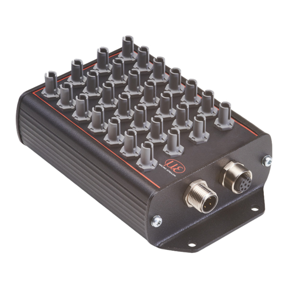
Page 13: Electrical Connections Controller
The power supply and communication connections of the controller are accessible using standardized male and female connectors M12. All connection cables with the features required for the application (e.g. drag chain compatibility or resistance to oil) and the matching coding can be used with the controllers. colorCONTROL MFA-7/-14/-21/-28 Page 13... -
Page 14: Supply Voltage
CAB-M12-4P-co-fm- straight Use a shielded cable with a length < 30 m. MICRO-EPSILON recommends using the optionally available CAB-M12-4P-co-fm-straight cable. 4.4.4 Data Transmission for RS422, RS232 or USB 8-pin female connector for connecting the RS422, RS232 or USB interface. Depending on the interface, there is a sepa-... -
Page 15: Rs422 (With If2001/Usb Converter)
Cable color from the voltage (Cable: CAB-M12- Function Function supply. 8P-co-straight) Use a shielded cable Blue with twisted wires, e.g. CAB-M12-8P-co- Pink straight. Gray White Fig. 5 Crossed data lines on receive and transmit side colorCONTROL MFA-7/-14/-21/-28 Page 15... -
Page 16: Operation
Connect the controller to the downstream display or monitoring units and to the voltage supply. Operation using sensorTOOL sensorTOOL by MICRO-EPSILON is a piece of software that you can use to apply settings to the controller and to view and document measurement data. You can find it online at https://www.micro-epsilon.com/download/software/sensor-... -
Page 17: System Parameterization Via Sensortool (Settings Menu)
Save in RAM button or in the MFA-7/14/21/28 controller using the Save permanently button. If you just want to save it in the RAM, the settings will be lost when you restart the controller and the adjustment will have to be carried out again. However, you can permanently save the settings under Settings/Configuration later. colorCONTROL MFA-7/-14/-21/-28 Page 17... -
Page 18: Configuration
The color temperature CCT and dominant wave- length d take longer to calculate, thus reducing the possible data rate many times over. Fields with dark border require entry of a Fields with gray background require a selection. Value value. colorCONTROL MFA-7/-14/-21/-28 Page 18... -
Page 19: Global Settings
Indicates the dominant wavelength for each active measuring Global settings length channel in nanometers. Output acquisition time- A timestamp documents the time of the measurement. stamp Fields with dark border require entry of a Fields with gray background require a selection. Value value. colorCONTROL MFA-7/-14/-21/-28 Page 19... -
Page 20: Channel Overview
By clicking on the button, a sensible combination of the parameters Integration time and Gain level is determined automatically for the selected channel. This button can be used to reset the intensity adjustment for the current channel. colorCONTROL MFA-7/-14/-21/-28 Page 20... -
Page 21: Measurement Menu
When data acquisition is stopped, the time graph curve is reset (deleted). Data acquisition starts auto- matically when you switch to the Data Acquisition menu. Click on the button to start the data acquisition. Data acquisition Click on the button to stop the data acquisition. colorCONTROL MFA-7/-14/-21/-28 Page 21... -
Page 22: Signal Processing
It has no effect on the measured values output by the MFA controller. Resets the master. Reset Fields with dark border require entry of a Fields with gray background require a selection. Value value. colorCONTROL MFA-7/-14/-21/-28 Page 22... -
Page 23: Data Acquisition Table
Click on this button to save the current measurement value selection. Format Point / comma Data acquisition CSV output Separator Comma / semicolon / tab Fields with dark border require entry of a Fields with gray background require a selection. Value value. colorCONTROL MFA-7/-14/-21/-28 Page 23... -
Page 24: Single Value Menu
Fig. 12 Measurement view (Single Value menu) in the sensorTOOL program In this menu, you can view the display of up to 9 measured values in an enlarged view. The measured values can be selected by activating them in the list. colorCONTROL MFA-7/-14/-21/-28 Page 24... -
Page 25: Color Display Menu
(depending on your monitor calibration settings). When you move the cursor over the individual channels, you will get a tooltip with the current measured values in the graph. These values can also be found in the table below the graph. colorCONTROL MFA-7/-14/-21/-28 Page 25... -
Page 26: Info Menu
Import settings will open the Explorer and give you the option of importing controller settings from a default *.csv file on the PC. We recommend that you always back up the current settings externally on your computer after you have set up the system. colorCONTROL MFA-7/-14/-21/-28 Page 26... -
Page 27: Disconnecting
Each value is transmitted in 3 data bytes (color or additional value) with 18 useful bits each. You can find more information on the measurement data format in the appendix , see A Only disconnect or connect the sub-D connection between the RS422 and USB converter when no voltage is flow- ing. colorCONTROL MFA-7/-14/-21/-28 Page 27... -
Page 28: Cleaning
MICRO-EPSILON or to your distributor / retailer. MICRO-EPSILON undertakes no liability whatsoever for damage, loss or costs caused by or related in any way to the product, in particular consequential damage, e.g., due to... -
Page 29: Service, Repair
Here you can inform yourself about the respective national collection and return points. - Old devices can also be returned for disposal to MICRO-EPSILON at the address given in the imprint at https://www.micro-epsilon.de/impressum/. - We would like to point out that you are responsible for deleting the measurement-specific and personal data on the old devices to be disposed of. -
Page 30: Appendix
PS2020 Power supply for top-hat rail 2420062 installation, input 230 VAC, output 24 VDC/2.5 A PS2031 Plug-in power pack 2420096 24V/24W/ 1A; 2m-PVC; Ter- minal-2P-BU-ge USB cable CAB-M12-8P-co- USB cable 2 m long 11235025 straight; 2m-PVC; colorCONTROL MFA-7/-14/-21/-28 Page 30... - Page 31 RS422 CAB-M12-8P-co- Connection cable, 10 m, 11234725 straight; 10m-PUR; open ends, for data transmis- open ends sion via RS422 Receiver sensor MFS-22 10825504 MFS-K04 10825506 MFS-K04-3 10825508 MFS-K04-6 10825510 MFS-K05/90 10825512 colorCONTROL MFA-7/-14/-21/-28 Page 31...
-
Page 32: Factory Settings
The ZIP file with the current firmware update tool Update_Sensor.exe and the firmware can be found on our website https://www.micro-epsilon.com/download/software/colorCONTROL-MFA-7-serie-Firmware.zip If you have any questions, please do not hesitate to get in touch with the relevant sales representative in our team. colorCONTROL MFA-7/-14/-21/-28 Page 32... -
Page 33: A 4 Ascii Communication With Sensor
(“Wxxx”) may be output. Warnings are structured analogously to error messages. In the case of warning messages, the command has been executed. For support requests regarding the sensor, the responses to the commands GETINFO and PRINT are helpful because they contain the sensor settings. colorCONTROL MFA-7/-14/-21/-28 Page 33... -
Page 34: A 4.1 Commands Overview
INTEGRATIONTIME Set exposure time Chap. A 4.5.4 AVERAGING Set moving average of measured values Chap. A 4.5.5 COLORSPACE Setting a color space for output Chap. A 4.5.6 GETMEASURE Output of a measurement result for selected channels colorCONTROL MFA-7/-14/-21/-28 Page 34... -
Page 35: System
GETINFO, Sensor Information GETINFO Request sensor information. Output see example below: ->getinfo GETINFO Name: MFA-7 //Model name Serial: 1001 //Serial number Option: //Sensor option number Article: 11094994 //Sensor article number Version: 1.2.3 //Software version Hardware-rev: -> colorCONTROL MFA-7/-14/-21/-28 Page 35... -
Page 36: A 4.2.3 Status
GETCHANNELCNT 28 COLORSPACE XYZ INTEGRATIONTIME DATARATE 100.0 OUTPUT ON GAIN OUT CH01 CH02 CH03 CH04 CH05 CH06 CH07 TIMESTAMP GETINFO AVERAGING Name: MFA-28 Serial: 0007 Option: 000 Article: 11094997 Version: 1.2.1 Hardware-rev: 00 GETOUTINFO -> STATUS colorCONTROL MFA-7/-14/-21/-28 Page 36... -
Page 37: Getchannelcnt
OUT [CH<d><d> ...] [TEMPERATURE] [WAVELENGTH] [TIMESTAMP] Select the output values for the serial interface, such as the channel numbers (CH01 ... CH28, temperature, wavelength and timestamp), that are to be output via the measurement data stream. colorCONTROL MFA-7/-14/-21/-28 Page 37... -
Page 38: Getoutinfo
AUTOGAIN operation is being performed. A 4.5.2 GAIN GAIN ALL|CH<d><d> [<num>] Set the hardware amplification level. There are 12 amplification stages from 0 to 11. The amplification stage is 2^<num>, i.e. the maximum amplification is 2048x. colorCONTROL MFA-7/-14/-21/-28 Page 38... -
Page 39: A 4.5.3 Integrationtime
A 4.5.5 COLORSPACE COLORSPACE [XYZ|xyY|Luv|uvL|RGB] Define the color space to be used for the output of color values. A 4.5.6 GETMEASURE GETMEASURE Provides the latest recorded measurement results for all channels or for the specified channel. colorCONTROL MFA-7/-14/-21/-28 Page 39... -
Page 40: Ascii Error Codes
E215 ERROR_CODE_TEXTCOMMANDER_HANDLING_OVERFLOW_ER- Input or command buffer overflow E232 ERROR_CODE_TEXTCOMMANDER_HANDLING_PARAMETER_ Incorrect number of parame- COUNT_ERROR ters E234 ERROR_CODE_TEXTCOMMANDER_HANDLING_PARAMETER_ER- Missing/unexpected param- eters or incorrect parameter type E236 ERROR_CODE_TEXTCOMMANDER_HANDLING_PARAMETER_ Invalid parameter value CONTENT_ERROR E301 ERROR_CODE_AUTOGAIN_ALREADY_RUNNING Autogain is already running colorCONTROL MFA-7/-14/-21/-28 Page 40... -
Page 41: A 5 Measurement Data Format
- reducing the measuring frequency, see A 4.3.3 The sequence for a complete data frame (all 168 signals active) is: Ch01_Color1 Ch01_Color2 Ch01_Color3 Ch01_Temperature Ch01_Wavelength Ch01_Timestamp Ch02_Color1 Ch02_Color2 Ch02_Color3 Ch02_Temperature Ch02_Wavelength Ch02_Timestamp … Ch28_Color1 Ch28_Color2 Ch28_Color3 Ch28_Temperature Ch28_Wavelength Ch28_Timestamp colorCONTROL MFA-7/-14/-21/-28 Page 41... - Page 42 0 - 0 raw value - offset scaled color = scaled color = 1310 factor 0 - 0 0 - 0 scaled color = raw value - offset scaled color = 1310 scaled color = 1310 factor colorCONTROL MFA-7/-14/-21/-28 Page 42...
- Page 43 - offset 0 - 0 scaled color = scaled color = factor 1024 0 - 0 scaled color = 1024 raw value - offset 0 - 0 scaled color = scaled color = factor 1024 colorCONTROL MFA-7/-14/-21/-28 Page 43...
- Page 44 MICRO-EPSILON Eltrotec GmbH Manfred-Wörner-Straße 101 · 73037 Göppingen / Germany Tel. +49 (0) 7161/98872-300 · Fax +49 (0) 7161/98872-303 X9751434-A012022DTa eltrotec@micro-epsilon.com · www.micro-epsilon.com Your local contact: www.micro-epsilon.com/contact/worldwide/ MICRO-EPSILON MESSTECHNIK...
Need help?
Do you have a question about the colorCONTROL MFA and is the answer not in the manual?
Questions and answers