Table of Contents
Advertisement
Quick Links
Advertisement
Table of Contents

Related Manuals for SME 60


Summary of Contents for SME 60
- Page 2 SME is an iconic brand founded in 1946 by audio legend Alastair Robertson-Aikman in West Sussex, England. Today SME is recognised as makers of the finest precision turntables and tonearms in the world. Entirely made in-house with state of the art manufacturing processes, complemented by traditional craftsmanship methods.
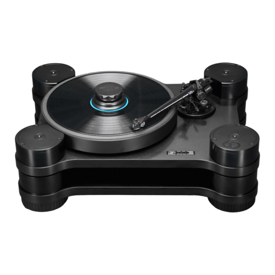
- Page 3 MODEL 60 PRECISION TURNTABLE INSTRUCTIONS This is no ordinary turntable. These instructions include unpacking, set up procedures and specifications. Please read carefully.
- Page 4 Warning! Important Safety Instructions CAUTION: RISK OF ELECTRIC SHOCK DO NOT REMOVE POWER UNIT COVERS. CAUTION: TO REDUCE THE RISK OF ELECTRIC SHOCK, DO NOT REMOVE THE POWER UNIT OR SPEED CONTROL UNIT COVER. THERE ARE NO USER SERVICEABLE PARTS INSIDE. REFER ALL SERVICING TO QUALIFIED PERSONNEL. •...
-
Page 5: Table Of Contents
1. CONTENTS TURNTABLE Page Introduction Overview Weights & Dimensions Drive System Speed Ranges Packing List Identification - Turntable Unpacking Setting Up - Turntable Power Cable Connections Operation - Turntable Operation - Playing a Record Maintenance Transit Precautions TONEARM Introduction Overview General Arrangement Set Up & Operation Guarantee Appendix... -
Page 6: Introduction
AC motor with remote (separate) power transformer. In addition the legendary SME Series V tonearm has been extensively sonically improved by use of a non-metallic tonearm tube made from an advanced polymer resin material with high density and high rigidity properties and importantly acoustically inert. With a low effective mass... -
Page 7: Overview
3. OVERVIEW 1. Speed Control Unit 5. Platter Suspension Column 2. Power Button 6. Record Clamp 10. Sub Chassis 3. Rotary Speed Control Tonearm 11. Main Chassis Air Vents Power Unit 12. Adjustable Foot 1. Power Unit 6. Left RCA Phono Output 11. Earth Post - Turntable 2. Power Unit Output 7. Phono Ground 12. Power Unit Input 3. Voltage Ident Label 8. Right RCA Phono Output... -
Page 8: Weights & Dimensions
4. WEIGHTS & DIMENSIONS WEIGHTS: Turntable 48kg Speed Control Unit Power Unit 4.2kg Boxed Shipping Weight 86kg DIMENSIONS: Turntable Height 212mm (top of clamp) Width 557mm Depth 417mm Speed Control Unit Height 87mm Width 170mm Depth 295mm Power Unit Height 83mm Width 190mm Depth 243mm Platter 330mm Spindle to Arm 215.35mm 5. -
Page 9: Packing List
7. PACKING LIST TURNTABLE Model 60 Chassis Assembly Platter Stroboscopic Disc Speed Control Unit Power Unit Connection Cable ‘A’ 1 Connection Cable ‘B’ AC Power Cable Record Clamp Record Spindle Washer Drive Belt Syringe of Bearing Spindle Oil Bearing Spindle Oil Filler Adaptor Bearing Spindle Oil Filler Box Spanner Syringe of Tonearm Damping Fluid Finger Lift with 2 Washers Cartridge Screws (Stainless Steel Set) 1 Cartridge Screws (Aluminium Set) TOOL KIT Cartridge Screwdriver - Flat Blade Cartridge Screwdriver - 2mm Hex 5mm Spanner (Cartridge Screws) 1/16 A/F Hex Wrench 0.89mm Hex Wrench 2mm Hex Wrench 2.5mm Hex Wrench 3mm Ball-ended Hex Handle 4mm Hex Wrench Suspension Adjustment Key (4mm) Suspension Height Gauges (5mm) Motor Height Setting Gauge (2mm) Spirit/Bubble Level Alignment/Height Protractor... -
Page 10: Identification Turntable
8. IDENTIFICATION TURNTABLE Platter Driven Pulley Suspension Column Motor Tonearm Base Motor Pulley Pulley Transit Chassis Transit Screw (x4) Screw (x4) PLAN VIEW Suspension Adjustment 4mm Hex Key Figure 1 RCA Phono Connectors Connection Cable Input REAR VIEW Figure 2... - Page 11 Height Gauge Spindle Tonearm Base Suspension Column Sub-Chassis Main Chassis Adjustable Foot Bearing Dampening Bath Tonearm Wiring Earth Post Spindle Base Housing SIDE VIEW R/H Figure 3 Acoustic Platter Mat Motor Pulley Platter Driven Pulley Sub-Chassis Height Gauge Main Chassis Feet Isolators Motor Earth...
-
Page 12: Unpacking
H aving opened the packing case lid carefully lift upwards the top section high density foam module which covers the turntable/ tonearm unit. Due to the weight of the Model 60 turntable it is best lifted out of the case by two people, one at each end and lifting from under the main chassis (bottom of turntable) and not the upper sub-chassis. The turntable should be sited on a substantial... -
Page 13: Setting Up - Turntable
10. SETTING UP - TURNTABLE With the turntable unpacked and sited follow the turntable setting up procedures in the order detailed below: Levelling the Turntable W ith the use of a spirit/bubble level ensure that the main chassis (lower chassis) is level in the lateral and longitudinal planes. The 4 feet are height adjustable and can be used to achieve a level chassis. When adjusting the feet it is recommended to slightly lift the chassis adjacent to the foot being adjusted. This aides ease of rotation of the foot and prevents the foot rubber pad binding. Levelling the Motor a. T he motor is mounted on 3 height adjustment screws, the points of which sit in compliant cups in the chassis base. For transit purposes these screws have been backed off clear of the compliant cups. - Page 14 The mains voltage setting is indicated on the rear panel of the power unit. Before fitting the mains power cable check carefully that this matches your mains voltage. WARNING To meet international safety standards the power supply unit is earthed through the yellow/green wire of the power cable and particular care must be taken to ensure that this is connected so as to maintain effective earthing should the original mains plug be changed. Tonearm Installation The Model 60 is equipped with a factory fitted SME Series VA tonearm. Under no circumstances attempt to remove the tonearm as it is wired directly to the RCA phono output sockets.
-
Page 15: Power Cable Connections
12. POWER CABLE CONNECTIONS Left RCA Phono Output Right RCA Phono Output Power Unit Speed Control Unit AC Power Cable Phono Ground Connection Cable ‘A’ Connection Cable ‘B’ NOTE: • Mains power must be off when connecting cables. -
Page 16: Operation - Turntable
13. OPERATION - Turntable The Model 60 precision turntable is partly run-in before leaving the factory but will benefit and improve after a few weeks of use. Do not worry if initially the bearing is not totally silent. A slight ‘swish’ barely audible at very close range in a silent room will quickly disappear after use of the turntable. If you should wish to check the speed settings and make your own adjustments the procedure is as follows: M ains Power: the power ON/OFF button is located on the rear of the power unit. With power ON the last used speed indicator LED light will illuminate on the speed control unit fascia. -
Page 17: Operation - Playing A Record
T he life of the suspension bands will depend on climatic conditions. If eventually they should stretch beyond further adjustment, replacement suspension bands are available directly from SME Limited. C hanging the suspension bands should only be conducted by an experienced technician or at the supplying dealer. A technical instruction process can be obtained from SME Limited. -
Page 18: Transit Precautions
16. TRANSIT PRECAUTIONS The Model 60 can be safely transported. SUBJECT TO THE FOLLOWING PRECAUTIONS: Short journeys by car: remove the platter, disengage the drive belt from the motor pulley, back off the motor height adjustment and refit the motor transit screw. Lock down the sub-chassis suspension. Screw down the four driven pulley transit screws lightly and evenly, just enough to prevent the pulley rotating. The turntable itself is best placed on a flat floor of a car boot/trunk. The platter and other items can be carefully protected and packed separately from the turntable. For all other transportation... - Page 19 HIGH DENSITY TONEARM INSTRUCTIONS This is no ordinary tonearm. These instructions include set up procedures, adjustments and specifications. Please read carefully.
- Page 20 17. CONTENTS Page Introduction Overview 23 General Arrangement Set Up & Operation 33 Guarantee 34 Appendix...
-
Page 21: Introduction
18. INTRODUCTION The Series VA (Advanced) Tonearm. With over sixty years of tonearm design, engineering and manufacturing experience, SME is accredited as makers of the best tonearms in the world. For over three decades the SME Series V Magnesium tonearm has been the global reference standard, but with the introduction of the Series VA High-Density tonearm a new reference standard has been established. The Series VA tonearm has only been made possible by decades of precision audio engineering knowhow and new technology materials. The Series VA tonearm tube is CNC precision machined in one piece from an advanced polymer resin high density material which is acoustically inert. The tonearm tube has a tri-lobular cross sectional shape which provides improved rigidity, the headshell is streamlined and modern in design. Importantly the Series VA has a very low resonance signature and... -
Page 22: Overview
19. OVERVIEW 1. Headshell 11. Balance Weight 2. High Density Tonearm 12. VTF Control 3. Arm Lift 13. Base Slideway 4. Damper Reservoir 14. Base Clamp Bolt 5. Damper Reservoir Cover 15. HTA Key 6. Dip Screw Lock Nut 16. Anti-Skate Control 7. Dip Screw 17. Base 8. VTA Screw 18. Control Lever 9. Balance Thumbwheel 19. Control Bracket 10. Balance Weight Clamp Lever 20. Arm Rest... -
Page 23: General Arrangement
20. GENERAL ARRANGEMENT HIGH DENSITY TONE-ARM DIMENSIONS SPECIFICATION A - Distance (pivot to stylus) 233.15 Effective Mass: 10g - 11g B - Distance (pivot to spindle) 215.35 Cartridge Balance Range: 5g - 18g C - Cartridge (fixing centres) 12.70 Vertical Tracking Force: 0.0g - 3.0g (30mN) D - Offset Angle 23.635⁰ Maximum Tracking Error: 0.012⁰/mm E - Linear Offset 93.47 Null Points: Inner - 66.04mm Outer - 120.9mm F - Overhang 17.80... -
Page 24: Set Up & Operation
The washers must also be used without the finger lift as they are required to protect the enamel finish when the cartridge fixing screws are installed. For high compliance cartridges the supplied aluminium screws and nuts offer some reduction in the tonearm’s effective mass. It is recommended that the SME supplied screwdrivers (flat blade or 2mm hex blade) and 2mm spanner are used for installing a cartridge to the Series VA tonearm headshell. Tighten the cartridge fixing screws sequentially and securely taking care not to over tighten. Note: The cartridge screws are non-magnetic. Damage can be caused if a screw is snatched by magnetic attraction whilst being offered up to the cartridge. For the same reason do not lay tools down nearby. WARNING Socket cap screws make high compression forces possible. Avoid over-tightening with cartridges having non-metallic mounting surfaces. - Page 25 Cartridge Lead Replacement The tonearm internal wiring terminates in a four-pin plug at the back of the headshell. The cartridge leads can therefore be replaced and can be obtained from your dealer or direct from SME. They should be fitted with due regard to their colour coding. Longitudinal Balance Step 1 The balance weight clamp lever is unlocked by moving it anti-clockwise. When required the action of the clamp lever can be adjusted as follows: Remove the central screw and lift the clamp lever upwards from its boss, using a slight rocking movement. Replace the lever in a new position one spline at a time, anti-clockwise to increase locking pressure and clockwise to reduce it.
- Page 26 Height (VTA) Adjustment Step 1 Insert the VTA screw into its socket as shown. Rotate clockwise until resistance is felt. Further rotation will increase the height of the tonearm relative to the base. Step 2 To lower the tonearm turn the VTA screw anti-clockwise. Finger pressure will then move the tonearm downwards until it stops on the screw, at which point further movement in either direction can be made as needed. Take care not to bend the VTA screw either by accidentally knocking it. Step 3 As the possibility of accidental damage cannot be ruled out, the use of an old record for the following procedures is recommended. Place the tonearm about halfway across the record and move the control lever forward to lower it into the playing position. Adjust the tonearm height until there is approximately 3mm clearance between the underside of the tonearm and the surface of the record at its circumference.
- Page 27 Step 5 Re-position the protractor about 6mm from the edge of the record. Using the scale repeat the measurement and compare it with the first one. Adjust the VTA screw until similar readings are obtained indicating that the tonearm is level with the surface of the record. Other dispositions can of course be accommodated and if the readings are noted can be quickly implemented for special needs. Horizontal Tracking Angle (HTA) Adjustment Step 1 Insert the HTA key into the socket situated centrally in either of the base slideways. Use a light pressure rocking it slightly to ensure full engagement of the pinion with the toothed rack in the base. Rotation of the key in either direction will now allow the base to move between the slideways (do not use force). If the movement is tight, check that the clamp bolts are sufficiently released. When all is well rotate the key to traverse the tonearm into its fully forward position. Step 2 With the record still on the turntable fit the bush and alignment protractor. Check that the anti-skate control is at zero and the VTF control is set to suit the cartridge in use. The stylus position on the protractor is indicated by a cross.
- Page 28 Step 4 Most cartridges have a stylus fixing hole centre distance of 9.5mm. Correctly adjusted with these the outlines of the tonearm and protractor will coincide when viewed directly above the centreline of the tonearm. With others, according to the position of the stylus, it will be necessary to view slightly to the left or right of the centreline. The only requirement for correct HTA being that the outlines appear to coincide along their length as shown. Place the tonearm in the armrest and remove the alignment protractor, leaving the bush on the record spindle.
- Page 29 Operation Step 1 With the control lever in the raised position move the tonearm off the armrest. Step 2 Position the tonearm so that the stylus is over the selected band of the record. Step 3 To lower the stylus onto the record move the control lever forward just over top centre. This will set the lowering control in motion, at which point it will take over the movement of the lever. For the correct descent time the control must be operated in this way. The speed will be increased considerably if the lever is pushed down rather than moving of its own accord. Step 4 To raise the stylus from the record move the control lever back to its original position. When the tonearm is not in use it should always be returned to the armrest for safety. This also closes the damper reservoir cover and protects the fluid from foreign matter.
- Page 30 Adjusting Height of Lift The raising and lowering control is set to suit the majority of cartridges but the height raised above the record can be changed to meet individual needs. The small hole in the centre of the arm lift provides access to the adjustment screw. Insert the long leg of the 0.89mm hex wrench through this hole to engage the screw. Clockwise rotation will decrease the height of lift, anti-clockwise rotation will increase height. The adjustment is sensitive so the wrench should be turned only a few degrees at a time. Filling the Damper Reservoir Step 1 With the control lever in the raised position, move the tonearm off the armrest, swinging it towards the turntable spindle as far as it will go. This will open the reservoir cover. Step 2 Remove the cap and seal from the syringe and holding it as shown slowly depress the plunger to expel the fluid. Fill from the rear and work forwards pausing from time to time while the fluid settles. Step 3 Only the lower section of the reservoir has to be filled. The deep rim is to prevent spillage in the event of rapid arm movement. The syringe contains sufficient fluid for two fillings. Replace the cap, seal with adhesive tape and store safely. We recommend an annual fluid change. Use only genuine fluid obtainable from your dealer or direct from SME. WARNING: Silicone fluid can cause discomfort if introduced into the eyes. It is therefore advisable to wash your hands at this point.
- Page 31 Operating the Damper Step 1 The degree of damping is controlled by a dip-screw and its depth of engagement with the fluid, from which it can also be withdrawn when damping is not required. To release the dip-screw for setting, the locknut should be rotated anti-clockwise about two turns. Step 2 Clockwise rotation of the dip-screw increases damping and anti-clockwise rotation reduces dampening. The ident rings on the screw are for reference, allowing setting to be noted and repeated. The system applies damping in the horizontal plane only.
- Page 32 Step 2 With the same 1/16 A/F hex wrench remove the two socket cap screws securing the damper reservoir to the control bracket. It can now be lifted clear and inverted on tissue paper to drain. The VTA screw works in a brass nut housed in the control bracket and this will be visible when the reservoir is removed. Do not interfere with it. Wipe out any fluid remaining in the reservoir with tissue and wash it and its cover with a small soft brush in warm water to which a few drops of washing-up liquid added. Dry with a clean tissue. Re-assemble in the reverse order, entering the screws carefully taking care not to cross the threads. Tighten firmly and evenly, only when all the screws have been fitted. Do not over-tighten. Cleaning the Arm Lift If the tonearm drifts outwards during raising and lowering it usually indicates the presence of contaminant on the rubber pad in the arm lift. To restore positive working wipe the pad with a damp cloth and repeat with a paper tissue until...
-
Page 33: Guarantee
22. GUARANTEE Your SME Model 60 turntable is guaranteed against faulty material and workmanship. The nominal period of the guarantee is 24 months but is liberally interpreted at SME’s discretion subject to the following conditions being observed: A ny matter arising must in the first instance be reported to SME Limited at the address appearing below. -
Page 34: Appendix
BS EN 62368-1:2014 International Safety Standard. For the purposes of testing the SME Model 60 Turntable was used with the high quality interconnects supplied as standard equipment. Compliance with the above standards may only be made if the unit is installed as per this instruction manual and using the correct cables. SME Limited · Mill Road · Steyning · West Sussex · BN44 3GY · England Printed in Steyning England... - Page 36 SME LIMITED STEYNING WEST SUSSEX ENGLAND • • •...
Need help?
Do you have a question about the 60 and is the answer not in the manual?
Questions and answers