Table of Contents
Advertisement
Quick Links
Advertisement
Table of Contents

Related Manuals for SME Model 6 Classic


Summary of Contents for SME Model 6 Classic
- Page 1 CLASSIC INTEGRATED PRECISION TURNTABLE OWNERS MANUAL...
- Page 2 CLASSIC INTEGRATED PRECISION TURNTABLE Instructions This is not an ordinary turntable. These instructions cover unpacking, adjustment and installation procedures and you owe it to yourself to read them carefully before proceeding further.
- Page 3 Warning! Important Safety Instructions: RISK OF ELECTRIC SHOCK DO NOT REMOVE SPEED CONTROL UNIT COVER CAUTION: TO REDUCE THE RISK OF ELECTRIC SHOCK, DO NOT REMOVE THE SPEED CONTROL UNIT COVER. THERE ARE NO USER SERVICEABLE PARTS INSIDE. REFER ALL SERVICING TO QUALIFIED PERSONNEL. •...
- Page 4 IMPORTANT NOTICE: The mains lead on this equipment when supplied for use in the UK, is fitted with a moulded plug incorporating a fuse. The value of the fuse is indicated on the pin face of the plug and if it required replacing a fuse approved to BSI 1362 of the same rating must be used. Never use the plug with the fuse cover omitted if the cover is detachable.
- Page 5 Introduction Model 6 Precision Turntable The SME Model 6 turntable is built to exacting engineering standards providing reliability and freedom from critical adjustments. Build integrity, sophisticated electronics and vibration free moving parts allow the full capabilities of this premium sound system to be fully explored.
-
Page 6: Table Of Contents
Contents Weights & Dimensions Packing List Parts Identification Unpacking Setting Up Operation – Speed Control Operation – Turntable Pick-up Arm Maintenance Warranty... -
Page 7: Weights & Dimensions
1. Weights & Dimensions (mm) Turntable Width: 420 Depth: 320 Height: 128 Platter Diameter: 300 Spindle to Arm: 215.4 Net Weight: 9.1kg Speed Control Unit Width: 220 Depth: 200 Height: 85 Net Weight: 2.05kg Power Consumption: Idle 5W - Max 10W... -
Page 8: Packing List
2. Packing List Description Part No. Model 6 Serial No: ……………… □ Stroboscopic Disc 1087 □ Control Unit – 100V □ 115V □ 230V □ □ Power Cord – UK □ EUR □ USA □ □ Drive Belt □ Platter □... -
Page 9: Parts Identification
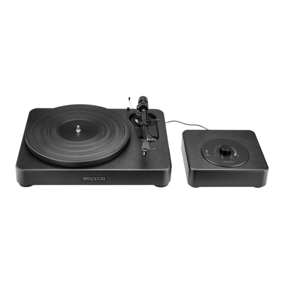
3. Parts Identification Speed Control Unit Power Button Rotary Speed Control Platter Bias Weight Bias Guide Way Rod Balance Weight Pick-up Arm 10. Finger Lift 11. Headshell 12. Way Rod / Rider Weight... - Page 10 Phono Connectors & Power Output Identification Low Voltage Mains Mains Input Power Cable 24V ON / OFF AC Socket Phono Output Earth Point Low Voltage Input Sockets Socket 24V...
-
Page 11: Unpacking
4. Unpacking 5. Setting Up 4. The power cord has a standard 1. Unpack and check all items against the 1. Drive belt fitment, place it over the moulded mains plug. In the event packing list in section 4. In the very driven pulley. -
Page 12: Operation - Speed Control
6. Operation – Speed Control 5. When the motor is running The Model 6 precision integrated turntable and the system will exit adjust mode is extensively run-in and it’s speeds set Pressing the power button on the and resume running normally. before leaving the factory. -
Page 13: Pick-Up Arm
8. Pick-up Arm • General Arrangements • Dimensions • Specifications • Fitting Balance & Bias Weights • Fitting Headshell & Cartridge • Pick-up Arm Set Up & Adjustment Note: Images for references only, mounting base plate profile may vary. For your convenience the Headshell is supplied detached from the tonearm ready for fitment of your cartridge. Cartridge not supplied –... - Page 14 General Arrangement...
- Page 15 Dimensions (mm) A – Pivot to Stylus 233.20 B – Pivot to Turntable Centre 215.40 C – Cartridge Fixing Centres 12.70 D – Offset Angle 23.63˚ E – Linear Offset 93.47 F – Overhang 17.80 G – Height above Mounting Surface (Max) 87.00 Height above Mounting Surface (Min) 63.00...
- Page 16 Anti-Skate Guide Accessory Balance Weight Tonearm Identification Balance Weight Anti-Skate Weight Anti-Skate Lever Arm Lift M3 Button Head Mounting Screw & Arm Mounting Washer Pillar Clamp Screw Bedplate Shield Can Wayrod/Rider Weight Arm Rest Catch Arm Rest Tone-arm VTA Thumbwheel Azimuth Locking Screw underside tone-arm at this point Base Clamp Nut &...
- Page 17 Fitting Headshell & Cartridge Before fitting the cartridge see that the Most cartridges have their own screws. Examine the top of the cartridge. It is stylus guard (not illustrated) is in position One pair #3-48 UNC x 11mm with nuts important that it presents a good flat face as a precaution against accidental damage.
- Page 18 BLUE GREEN BLUE GREEN BLUE GREEN WHITE WHITE WHITE Cartridge Lead Replacement Fitting Headshell Removing Headshell The cartridge leads. Part No. 1806, can be Insert the S2-R headshell into the arm Removal is the reverse of fitting. Holding replaced and may be obtained from your socket and press firmly inwards until the the headshell firmly to prevent rotation dealer or direct.
- Page 19 Pick-up Arm Set Up & Adjustment Longitudinal Balance Adjust until the arm, with the cartridge fitted, is either level or slightly low at the front end. With only the main balance weight fitted, cartridges up to 16g may be balanced. However by removing the balance weight end cap and coupling the accessory balance weight (as illustrated) cartridges up to 38g,...
- Page 20 Vertical Tracking Force (VTF) Adjustment For safety the lever of the lowering control VTF is set after longitudinal balancing has Half gram settings are indicated by the should now be moved in to the raised been completed. shallow grooves alternating with the position.
- Page 21 Vertical Tracking Force (VTF) Adjustment Release the pillar clamp screw, using the Use an old but unwarped record for the Repeat the measurement towards the 2mm A/F wrench, by one turn only. following procedures in case of accidental rear of the tonearm tube and compare it damage.
- Page 22 Azimuth Adjustment Place a small mirror on the turntable and Release the headshell clamp bolt by one Re-check with the mirror and when rest the stylus on it. Viewed in this way any quarter turn. The stylus must be clear of satisfied tighten the headshell clamp bolt departure from the vertical is accentuated the mirror whilst this is done.
- Page 23 Horizontal Tracking Force (HTF) Adjustment Place the tonearm into the armrest and With a record on the turntable and having Similarly check the outer point and adjust release the two base clamp nuts, using a pierced the alignment protractor for the the arm until the conditions shown in the stylus, place it on the turntable spindle.
- Page 24 Positioning the Armrest Release the pillar clamp screw using the Rotate the pillar to position the armrest conveniently in relation to the turntable. The 2mm A/F wrench. dimension ‘X’ should not be more than 110mm or less than 50mm. Height adjustment will be maintained by Tighten the pillar clamp screw firmly, avoiding excessive force.
- Page 25 Anti-Skate Adjustment Thread the filament through the guide Drop the loop into the groove corresponding Loosen the inner base clamp nut enough pulley housing and pass the loop over the to the vertical tracking force being used. to allow movement of the anti-skate guide. anti-skate lever.
- Page 26 Operation Rotate the control lever fully, in the Position the arm so that the stylus is over To lower the stylus onto the record move direction of the arrow, and move the the selected track of the record. the control lever forwards, in the direction tonearm out from the armrest.
- Page 27 Operation (continued) To raise the stylus from the record move the The raising and lowering control is set If the arm drifts outwards during raising or control lever back to its original position. to suit the majority of cartridges but the lowering it indicates contaminant on the When the arm is not in use it should always height raised above the record can be...
-
Page 28: Warranty
9. Maintenance – Turntable 10. Warranty 1. There are no critical adjustments or Your SME Model 6 precision turntable and b) Insurance should be effected by the need for ‘tweak’ and only very little owner. SME Limited are unable to pick-up arm is guaranteed against faulty maintenance. - Page 29 In the unlikely event of a problem concerning operation or service, always contact SME Limited in the first instance at the address at the bottom of Section 10 (WARRANTY), stating the exact nature of the problem, the name and address of the dealer who supplied the unit and its serial number which will be found on the label at the rear of the turntable base.
- Page 30 SME Limited. Compliance with the above standards may only be made if the unit is installed as per this manual and using the correct cables. Stuart McNeilis SME Limited · Mill Road · Steyning · West Sussex · BN44 3GY · England · +44 (0) 1903 814321...
- Page 31 Printed in Steyning England...
- Page 32 SME LIMITED STEYNING WEST SUSSEX ENGLAND • • •...
Need help?
Do you have a question about the Model 6 Classic and is the answer not in the manual?
Questions and answers