Table of Contents
Advertisement
Quick Links
Advertisement
Table of Contents

Subscribe to Our Youtube Channel
Related Manuals for janitza UMG510


Summary of Contents for janitza UMG510
- Page 1 Universal Measuring Device UMG510 Operating instructions UMG 510 Universal Measuring Device Janitza electronics GmbH Vor dem Polstück 1 D-35633 Lahnau Support Tel. (0 64 41) 9642-22 Fax (0 64 41) 9642-30 e-mail: info@janitza.de Internet: http://www.janitza.de...
-
Page 2: Table Of Contents
Table of contents Initial operation Precautions Power supply Safety precautions Voltage measurement Package Contents Current measurement Functional description Setup Functional description Display contrast Intendend usage Language selection Intended usage Connection diagrams Mounting Main input Measurement Connection TN and TT networks Voltage mode IT networks Potential transformer... - Page 3 Specifications Measurement uncertainty Declaration of conformity Safety regulations High voltage testing Electromagnetic compliance Dimension sketch Back view Side view Top view Connection example Appendix: Overview displays...
-
Page 4: Digital Input
All rights reserved. No part of this manual may be reproduced or duplicated without the written permis- sion of the author. Any contraventions are punish- able and will be prosecuted with all legal means. No liability can be taken for the faultless condition of the manual or damage caused by the use of it. - Page 5 Bedeutung der Symbole The symbols, which are used in this manual, have the following meaning: Beware of dangerous electrical voltage. This symbol shall warn you about possible danger, which can occur during installation, putting into service and usage. Protective ground terminal.
-
Page 6: Precautions
Precautions Appropriate transportation, storage and installation is required to ensure personal safety and proper operation of this unit. Before operating the unit please carefully read this instruction manual. Dis- connect and secure all power connections immedi- ately if safe operation is not possible. Do not mistreat the unit by using excessive force or inappropriate tools, when packing or unpackingas this may cause damage to the unit. -
Page 7: Functional Description
Functional description Functional description • automatic adaption to power line frequencies from 15Hz ... 75Hz • Measurement window 200ms, 10/12 cycles at 50/60 Hz, respectively • gapless sampling and calculation of: - rms voltage line-to-neutral - neutral point and unbalance L1 ... L3 - rms voltage line-to-line - frequency (same for all inputs) - rms current each input, sum L1 ... -
Page 8: Intendend Usage
In case of ground faults the maximum input voltage of the UMG 510 may be exceeded, this may The UMG510 is capable of continuous and non- be dangerous for the operator or may cause dam- monitored operation. Power supply and measured age to the unit. -
Page 9: Intendend Usage
Intendend usage Auxiliary measurement The auxiliary input can be used to monitor a single phase or symmetrical three phase system. The aux- iliary input can also be used to monitor the neutral current of the connected to the main input three phase system. -
Page 10: Installation
- A circuit breaker for the power supply must be pro- vided. - The circuit breaker must be placed near to the UMG510 and easily accessible. - The circuit breaker must be clearly marked. - Check the supply voltage with the type plate mark- ing before connecting. -
Page 11: Measurement
Installation Three phase auxiliary measurement Measurement Medium and high voltage Potential and current transformers are always re- quired for measurements in medium and high volt- age distribution systems. Special safety regulations have to be observed when using these transformers. Measurement circuits The UMG 510 provides two measurement inputs: one three-phase main measurement and one auxil- iary measurement. -
Page 12: Three Phase Meas. Without Neutral Cond
Installation Three phase main measurement with neutral conductor Fig. 4.1: Three phase measurement with neutral Fig. 4.1a: Three phase measurement with neutral conductor (3ph, 4w, 3m). conductor using potential transformers (3ph, 4w, 3m). Fig. 4.2: Three phase measurement with neutral Fig. -
Page 13: Three Phase Meas. Without Neutral Cond
Installation Three phase measurement without neutral conductor Fig. 4.6a: Three phase measurement without neutral Fig. 4.6: Three phase measurement without neutral conductor using potential transformers, 2 meter con- conductor in 2 meter configuration (3ph, 3w, 2m). figuration (3ph, 3w, 2m). Fig. -
Page 14: Voltage Measurement
Installation Voltage measurement The UMG 510 is designed to measure AC voltages up to 500VAC line-to-ground potential or 870VAC line-to-line. The wiring material must be suited for use with these voltages. The UMG 510 cannot be used to measure DC voltages. -
Page 15: Current Measurement
Installation Current measurement Summing current measurement The UMG 510 is designed to be used with current When using two or more current transformers for transformers. The nominal secondary current of the current measurement, the total transformer ratio CTs shall be 1A or 5A. must be set at the UMG 510. -
Page 16: Serial Ports
Installation Serial Ports Fieldbus (RS485) Termination resistors All units have to be connected in a single line bus structure. One segment holds up to 32 units. Use termination resistors on both ends of each segment. Repeaters must be used to connect the segments if more than 32 units or longer lines are needed. -
Page 17: Digital I/O
(terminal no. 11). Each tran- quire an input voltage of 10..28V at max. current of sistor can drive 30mA and withstands max. 28V 6mA. open circuit voltage. Externe Hilfsspannung UMG510 230V AC Digital inputs1-4 UMG510 3,9V 24V DC Digital outputs... -
Page 18: S0 Pulse Input
4 different tariffs, see table. according to EN62053-31. External power supply and resistor (1.5 kOhm) are required, see circuit diagram. Anzahl der Arbeitszähler Digital Input Arbeitszähler Nummer UMG510 Digital inputs 5-8 3,9V Digital Input 5 Abb. Arbeitszählerumschaltung 3,9V Digital Digital input 3 Input 6 External recording synchronisation. -
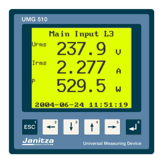
Page 19: Operating Instructions
Operating instructions Operating instructions Display contrast UMG 510 Hold key 1 and press key 4: increase contrast. Hold key 1 and press key 3: decrease contrast. Display selection Select main displays Universal Measuring Device Select sub displays Enter Setup Menu Hold key 6 for 2..3 seconds. -
Page 20: Initial Operation
Initial operation Initial operation Current measurement Connect the current measurement inputs one by To place the UMG 510 into operation follow these in- one and check the current and power readings with structions: the expected values. Short the current transformer - connect power supply secondary to see the current reading get smaller. -
Page 21: Setup
Initial operation Language selection Setup Choose from the available languages (English and After having done all the connections, do the setup German): of the UMG 510. Display contrast If the display is weak or empty, try adjusting the dis- play contrast. Hold key 1 (Esc) and press (repeatedly) key 3 or 4. -
Page 22: Connection Diagrams
Initial operation Connection diagrams Voltage mode Use this selection The UMG 510 provides 4 inputs for current and volt- to set the relevant age measurement. 3 Channels form the main meas- voltage. For power urement input for three-phase measurements. The quality analysis in fourth channel is called auxiliary measurement and low-voltage distri-... -
Page 23: Potential Transformer
Initial operation Potential transformer Current transformer Set the primary and secondary voltage of the poten- Set the primary and secondary current according to tial (voltage) transformer according to the type plate the type plate values of your CT. Carefully to set cor- values of the VT. -
Page 24: Events
Initial operation Events Transients setting setting nominal voltage nominal voltage and current in the and current, the previous menu, transient trigger the event thresh- thresholds will be olds will be set to set to default val- default values. ues. The defaults These default are are chosen to de- suitable for later... -
Page 25: Auxiliary Measurement
Initial operation Auxiliary measurement Measurement mode The auxiliary input If you decide to measure the neutral conductor cur- can be set to use rent, as seen in the circuit diagram, you'll have to set the summed volt- up the auxiliary input. Chose "Auxiliary measure- current ment"... -
Page 26: Check The Measured Values
Initial operation Check the measured values Current Press the Esc key repeatedly until the display re- Set the display to rms current reading. Check the turns to the measured value display. Select the displayed values measured value displays by using the arrow keys. with the real val- ues. -
Page 27: Recordings
Initial operation Recordings Data memory The data memory is about 14.5MB in size. If the ca- After having set up the unit and checked the meas- pacity of the memory is fully occupied, the oldest re- ured values, the data recordings can be started. corded data will be erased to achive space for new data. -
Page 28: Communication Settings
Initial operation Communication settings Fieldbus RS485 Ethernet (TCP/IP) Select one of the following fieldbus protocols: Set the IP address, netmask and default gateway Modbus Slave before connecting the UMG 510 to the network. Do Modbus Gateway not connect the UMG 510 to the network if the IP ad- Profibus DP dress for the UMG 510 is not known or not set. -
Page 29: System
Initial operation System Password Use the password to protect the setup menus. A This menu shows information about the unit and al- valid password is any number from 1 to 65535. Use lows to set a password to protect the setup menus. 0 to disable the password. -
Page 30: Display
Initial operation Display Display configuration Use this setting to select a default display which will Auto display be shown after an When turned on, the UMG 510 changes the display idle time. Further- successively through user selected displays. Use more you can se- the "display conf"... -
Page 31: Chart Speed
Initial operation Chart speed Date and Time This is the speed setting for the chart recorder dis- The UMG 510 shows the local time. Internal plays. Use small values for higher speeds (0 is fast- processing uses UTC time. est) and larger values for slower speed. Use a NTP Server to continuously synchronize the time. -
Page 32: Troubleshooting
Initial operation Troubleshooting Problem Cause What to do No display external fuse blown replace fuse internal fuse blown internal fuse is not user serviceable unit defective contact manufacturer for service weak or dark display contrast bad set contrast no current reading current transformer check wiring not connected or... -
Page 33: Service
- Supply voltage and measured voltage - exact description of your problem You’ll reach us: Mo - thur 07:00h bis 15:00h 07:00h bis 12:00h Janitza electronics GmbH Vor dem Polstück 1 D-35633 Lahnau Support: Tel. (0 64 41) 9642-22 Fax (0 64 41) 9642-30... -
Page 34: Maintenance
Initial operation Maintenance The unit contains no user serviceable parts. Do not dismantle the cabinet. Repair and calibration For repair and calibration return the unit to the manufacturer. Cleaning Use soft cloth with mild detergent to clean the front panel. Never use thinner, benzine, alcohol, abrasive clean- ers or other strong solvents, as this may cause dam- age to the front panel. -
Page 35: Measured Value Display
Initial operation Measured value display Used terms unbal Voltage unbalance EN 50160, EN 61000-2-4 auxiliary input capacitive crest factor Comparator displacement power factor, cos(phi) Disp PF displacement power factor, cos(phi) degree (phase angle) consumed energy delivered energy Flicker EN 60868, IEC 868 neg. -
Page 36: Specifications
Technical data Specifications Environmental conditions Overvoltage class CAT III Pollution degree Operating temperature -10 degC ... +50 degC Storage temperature -20 degC ... +60 degC Humidity 15% ... 95% R.H. non-condensing Altitude 0...2000m Protection class Front panel IP 50, IEC529 Front panel with optional gasket IP65, IEC529 Rear Cabinet... -
Page 37: Measurement Uncertainty
Technical data Measurement uncertainty The measurement uncertainty specification applies for the specified ranges, assuming the reading inside the given limits. Beyond the limits the uncertainty is not specified. If not otherwise specified, the frequency of all inputs is identical and in the range between 15 to 75Hz. The ambient temperature must be in the range between 18 to 28°C. -
Page 38: Declaration Of Conformity
Technical data Declaration of conformity The UMG510 fulfils the requirements of: Richtlinie 89/336/EWG in Verbindung mit DIN EN61326 (2002-03) sowie der Richtlinien 73/23/EWG und 93/68/EWG in Verbindung mit EN 61010-1 (2002-08) Safety regulations Sicherheitsbestimmungen für elektrische Mess- Steuer-, Regel- und Laborgeräte... - Page 39 Technical data...
-
Page 40: Dimension Sketch
Technical data Dimension sketch +0,8 +0,8 Cut out: 138 x 138 Back view... -
Page 41: Side View
Technical data Side view Top view Die grau gekennzeichneten Anschlüsse sind nicht in jeder Geräteausführung verfügbar. Alle Maße sind in mm angegeben. -
Page 42: Connection Example
Technical data Connection example... - Page 43 Overview displays Hauptwerte (U, I, P..) wählen. Display contrast. Hold key1 and press key 4: increases contrast. Hold key1 and press key 4: decreases contrast.
- Page 44 Overview displays Enter setup menu Hold key 6 for 2..3 seconds Select menu Select menu line. Confirm. Change settings. Move cursor forward. Move cursor back. Increment. Decrement. Confirm. Exit Menu. Exit menu.
Need help?
Do you have a question about the UMG510 and is the answer not in the manual?
Questions and answers