
Related Manuals for janitza UMG 500 A


Summary of Contents for janitza UMG 500 A
- Page 1 Universal Measuring Device UMG 500 A Janitza electronic GmbH Vor dem Polstück 1 D-35633 Lahnau Tel. (0 64 41) 9642-0 Fax (0 64 41) 9642-30...
-
Page 2: Table Of Contents
Universal Measuring Device UMG 500A Content Application Peak values Construction features Date and time Functional description Threshold contacts Installation Device Address Auxiliary voltage Software release Measurement inputs Serial interface Relay outputs K1 and K2 Connection PC to interface converter Analogue output “0..20 mA” Communication parameters “Clear work”... -
Page 3: Application
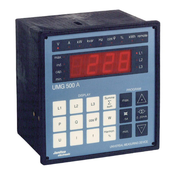
Universal Measuring Device UMG 500A Application Construction features Universal Measuring Device UMG 500A is suited for Universal Measuring Device UMG 500A is housed in a fixed front panel mounting and to meaure voltage, current, 144 mm x 144 mm plastic case suitable for front panels power etc. -
Page 4: Installation
Universal Measuring Device UMG 500A Installation When installing and mounting the Universal Measuring Device UMG 500A, the VDE Regulation 0113 must be adhered to. Before connecting up, ensure that the local supply conditions agree with the data given on the nameplate. The installation facilities must provide a switch or a power switch. -
Page 5: Commissioning
Universal Measuring Device UMG 500A Commissioning Connect auxiliary voltage. The 7-segment display shows “0”, or if a measured voltage is already present, another reading. Programming When the auxiliary voltage is present, the device is ready for use and can be programmed. To do this, the “local/remote”... -
Page 6: Functional Plan
Universal Measuring Device UMG 500A Functional plan Voltage App. Mean Mean Real App. React. React. Real Fre- power current I current real power P power S power Q work work W quency f factor 7. 11. 13. Measurement power cos phi function Harmonic wave 15 min./... -
Page 7: Factory Presettings
Universal Measuring Device UMG 500A Factory presettings • Current transformer: 5000A/5A • Voltage transformer factor • Measuring function voltage • Measurement phase • Device address (RS485) • Measuring period for real power mean value 900 seconds • Analogue output Function current Phase Scaling... -
Page 8: Key Functions And Programming
Universal Measuring Device UMG 500A Key functions and Programming Programming of Universal Measuring Device UMG 500A is carried out with the remote/local contact open, using the keyboard and the digital display. Following a power failure, it is not necessary to reprogram the device, because the programmed data and peak values are stored. -
Page 9: Voltage
Universal Measuring Device UMG 500A Voltage When this key is pressed, the device displays the effective value of the voltage to neutral or to the next phase (L1-L2; L2-L3; L3-L1). The unit is indicated by the LED “V”. Instruments with the option “kV” display the measurement value in the format ##.## kV. -
Page 10: Reactive Power
Universal Measuring Device UMG 500A Reactive power This function displays the reactive power in the outer conductors or the sum of their reactive powers. The unit “kvar” is indicated by an LED. The direction of the phase displacement between voltage and current is indicated by the LEDs “ind”... -
Page 11: Analogue Output
Universal Measuring Device UMG 500A Analogue output Allocation 0..20 mA In order to allocate a particular measuring function to the output, the desired measuring function .. / 5A and the measurement phase must first be selected. After this, the function set is allocated to the analogue output by operating the keys illustrated on the left. -
Page 12: Peak Values
Universal Measuring Device UMG 500A Peak values Universal measuring device UMG 500A stores the peak value and the date and time of registering for most of the measuring functions. There is no storage of peak values for real work and reactive work. In the case of harmonic waves, the peak values are stored without date and time. -
Page 13: Serial Interface
Bus connection The interface converter can be plugged in directly to the All measuring stations (UMG 500 A) are connected with COM port of a PC (25-pin plug) via the adapter provided one another via a four-core screened cable and to the 4-pin (socket-socket). -
Page 14: Setting The Device Address
Dimensions (Dimensions in mm) Device address Copyright © Janitza electronic GmbH 1995, 1996 This handbook may not be copied or reproduced by any means in whole or in part without the written permission of Janitza. Page 14... -
Page 15: Technical Data
Universal Measuring Device UMG 500A Technical data Auxiliary voltage: see nameplate Mains frequency: 50 Hz / 60 Hz Power consumption: approx.. 10 VA Measuring inputs Signal frequency: 45 ... 750 Hz Voltage paths Power consumption: 2.75 VA at 230 V Nominal measured voltage Standard: = 230 V (80 ... -
Page 16: Connection Example (3-Wire, Aron-Connection)
Universal Measuring Device UMG 500A Connection example (3-wire, internal Aron-connection) interface converter serial interface RS 485 - RS 485 RS 232 switch closed: remote switch open: local switch closed: clear work switch open: measure analogue output floating threshold contacts auxiliary voltage see nameplate consumer 50 mA .. -
Page 17: Connection Example (4-Wire)
Universal Measuring Device UMG 500A Connection example (4-wire) interface converter serial interface RS 485 - RS 485 RS 232 switch closed: remote switch open: local switch closed: clear work switch open: measure analogue output floating threshold contacts auxiliary voltage see nameplate consumer 50 mA .. -
Page 18: Connection Example (Aron-Connection)
Universal Measuring Device UMG 500A Connection example (Aron-connection) interface converter serial interface RS 485 - RS 485 RS 232 switch closed: remote switch open: local switch closed: clear work switch open: measure analogue output floating threshold contacts auxiliary voltage see nameplate consumer 50 mA .. - Page 19 Universal Measuring Device UMG 500A Declaration of Conformity The manufacturer Janitza electronic GmbH Vor dem Polstück 1 D-35633 Lahnau Tel. (0 64 41) 96 42-0 Fax (0 64 41) 96 42-30/-40 herewith confirms that the product Description: Universal Measuring Device...
Need help?
Do you have a question about the UMG 500 A and is the answer not in the manual?
Questions and answers