Table of Contents
Advertisement
Quick Links
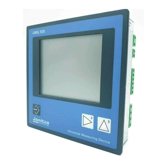
Universal Measuring Device
Operating Instructions
Mean value
Indicated phase,
- Phase against N,
- Phase against Phase,
- Sum measurement.
Peak values
Lowest values
Mark for the selected
values for ring buffer
Consumption
Supply
Key 1
UMG505
Brief instructions see last page
Current transformer
Harmonic number / Energy
meter
Voltage transformer
Device address
Indication of mode
Key 3
Key 2
Janitza electronics GmbH
Vor dem Polstück 1
D-35633 Lahnau
Support phone (0049-6441) 9642-22
Fax: (0049-6441) 9642-30
e-mail: info@janitza.de
Internet: http://www.janitza.de
Advertisement
Table of Contents

Subscribe to Our Youtube Channel
Related Manuals for janitza UMG505


Summary of Contents for janitza UMG505
-
Page 1: Operating Instructions
Lowest values Mark for the selected values for ring buffer Indication of mode Consumption Key 3 Supply Key 2 Key 1 Janitza electronics GmbH Vor dem Polstück 1 D-35633 Lahnau Support phone (0049-6441) 9642-22 Fax: (0049-6441) 9642-30 e-mail: info@janitza.de Internet: http://www.janitza.de... -
Page 2: Table Of Contents
Table of contents Generals Usage and display Receipt control Measured value indications SELECT Mode Meaning of symbols Configuration menu CONF Hints for maintenance Programming menu PRG Product description Mean values Intended use Minimum and maximum values Hints for usage Energy measurement Support Time of deletion Functional description... -
Page 3: Key
Configuration PSW505 Current transformer PC hardware Voltage transformer PC operating system Aron circuit Functions Data logging Configure the UMG505 Configure measured value indications Serial interfaces Read memory RS485 interface (Option) Terminal resistors Tables RS232 interface (Option) Table 1a, Measured values... - Page 4 All rights reserved. No part of this manual may be reproduced or duplicated without the written permission of the author. Any contraventions are punishable and will be prosecuted with all legal means. No liability can be taken for the faultless condition of the manual or damage caused by the use of it.
-
Page 5: Generals
Generals Receipt control Hints for maintenance In order to ensure a perfect and safe use of the Before delivery the device is tested in various safety device, a proper transport, expert storage, erection checks and marked with a seal. If the device is and mounting and careful usage and maintenance opened, these checks must be repeated. -
Page 6: Product Description
Product description Hints for usage Intended use The UMG505 is designed for fix mounting in low and This device may be put into service and used by qualified personnel according to the safety regulati- medium voltage switchgear and for measurement of ons and instructions only. -
Page 7: Functional Description
Diagr. Drawing UMG505 in TN-networks. and time in a ring buffer. 500V 50/60Hz Measurement in IT-networks The UMG505 can be used in IT-networks with outer conductor voltage up to 500V. Measurement in networks without N In networks without N, the voltages are measured against an artificial neutral point (PE). -
Page 8: Hints For Installation
Measuring voltage Supply voltage A supply voltage is necessary for the operation of The UMG505 is suitable for measurement of alternating voltage up to 500VAC against ground the UMG 505. The kind and dimension of the and 870VAC between the outer conductors. The required supply voltage is noted on the type plate. -
Page 9: Measuring Current
Measuring current The UMG505 is designed for the connection of current transformes with secondary currents of ../1A and ../5A. When the device is delivered, a current transformer of ../5A is set. Each currrent measurement input can be loaded with 5,2A over a long period or for 2 seconds with 180A. - Page 10 UMG505 UMG505 Hilfs- Hilfs- spannung spannung Messung Auxiliary Messung Auxiliary Mesurement Voltage Mesurement Voltage L/L 80 .. 870V AC L/L 80 .. 870V AC L/PEN 50 .. 500V AC 0,005 .. 5A L/PEN 50 .. 500V AC 0,005 .. 5A...
- Page 11 UMG505 UMG505 Hilfs- Hilfs- spannung spannung Auxiliary Auxiliary Messung Messung Voltage Voltage Mesurement Mesurement L/L 80 .. 870V AC L/L 80 .. 870V AC L/PEN 50 .. 500V AC 0,005 .. 5A L/PEN 50 .. 500V AC 0,005 .. 5A...
-
Page 12: Serial Interfaces
At the beginning and at the end of a segment the Baud should not exceed 15 up to 30 meters. The cable is terminated with resistors. In the UMG505 allowed load must be bigger than 3kOhm, The these terminal resistors can be activated with capacitive load, caused by the transmission cable, pluggable bridges. -
Page 13: Lon-Bus (Option)
LON-Bus (Option) Allowed cable length For the connection of the UMG505 with other LON- bus devices a FTT10-transceiver is used within the Depending on the selected structure of the network UMG 505. Hence, the bus is safed against change and the chosen cable type, different transmission of polarity and can be connected at one or two distances can be achieved. -
Page 14: Digital Inputs
85 .. signals. Input 4 can be used as pulse input for real 265VAC . energy measurement as well. UMG505 UMG505 Digital inputs Digital inputs 85..265VAC Digital... - Page 15 For the operation, DIN EN62053-31 or as digital input. For the an external supply voltage of 20..30V DC is required. operation, an external supply voltage of 20..30V DC is required. UMG505 UMG505 Digital inputs Digital inputs Pulse...
-
Page 16: Digital Outputs
Digital outputs The UMG505 has 5 transistor switching outputs. These outputs are separated from the evaluation electronics via optical couplings. The collectors of the transistors are connected together with plus po- tential (terminal 36). External Supply 230V AC 24V DC... -
Page 17: Analogue Outputs
Analogue outputs The UMG505 has 4 analogue outputs. Each analogue output can transmit a current of 0-20mA or 4-20mA. For the operation, an external net supply of 24VDC is required. External External supply supply 230V AC 230V AC 24V DC... -
Page 18: Putting Into Service
L-N and L-L must match the ones at measurement voltage input. If a The size of the supply voltage Uh for the UMG505 voltage transformer ratio is programmed, it has to must match the description on type plate. If be respected during this comparison. -
Page 19: Check All Phase Power
505 must show zero A in the corresponding outer Check sum power conductor. The current indicated by UMG505 must match the If all voltage, current and power are displayed input current respecting the set current transformer. correctly for the corresponding outer conductors, the sum values must be correct as well. -
Page 20: Removal Of Errors
Removal of errors Faults Possible reason Remedy Indication dark External prefuse has released. Replace prefuse. Internal prefuse has released. The fuse cannot be changed by the user. Please send the device back to the manufacturing works. Contrast setting too dark. Change contrast settings in configuration menu. - Page 21 Faults Possible reason Remedy Programming data lost Battery empty Please send the device to the manufacturer for replacement of the battery. Real power too small / Current transformer factor Read current transformer ratio on current too big programmed incorrectly. transformer and program correctly. Current path is assigned Check and correct connection.
-
Page 22: Usage And Display
Usage and display After net return, the UMG 505 shows always the first In configuration menu CONF and in programing programmed measured value indication. The use of menu PRG, the settings can be changed in edit the UMG 505 is carried out via the three keys in the mode EDIT. -
Page 23: Measured Value Indications
Measured value indications Configuration menu CONF After a net return the device always starts with the In configuration menu CONF the settings, which are first programmed measured value indication. In the necessary for the operation of the UMG 505, are indication of the UMG 505 up to three measured deposited. -
Page 24: Mean Values
Mean values For the most measured values a mean value is build The calling up - in the example for the power over the last passed period of time within the UMG maximum value in phase L3 - is carried out as 505 each second. -
Page 25: Minimum And Maximum Values
Minimum and maximum values For the most measured values (see table measured Example: Call up a maximum value and calculated quantities) the minimum and The maximum value „current in L2“ shall be called maximum values are saved. The minimum value is the smallest measured value, which was detected Move to the measu- since the last deletion. -
Page 26: Energy Measurement
Energy measurement In the UMG505, all in all 30 energy meters are at Time of deletion your disposal. For each energy meter, the running time is saved. If meters can be cont- real energy or reactive energy is deleted, all... -
Page 27: Show Running Time
Example: Running time for real energy T00: „Scanning frequency“. The running time for real energy can be called up in The UMG505 calculates harmonics up to the 20th. the measured value indication. From each program part, you reach the first measured value indication Total harmonic distortion THD(f) by pressing key 1 for about two seconds. -
Page 28: Emax
The monthly EMAX peak values can be read out For the comparison and storage of the monthly directly at the UMG505 and via the serial interface, Emax peak values, only that real power Emax is with the software PSW505, for instance. -
Page 29: Reset Of The Measuring Period
Reset of measuring period by keyboard Reset of the measuring period The averaging time for real power Emax is called With key 3 you scroll measuring period. to the indication of The measuring period for real power Emax can be real power EMAX. -
Page 30: Memory
Memory The memory of the UMG 505 is deviced into three Event memory ranges. The event memory, the maximum and In the event memory, the following events can be minimum memory and the ring buffer. The event saved with date and time: and the ring buffer can be read out with the program - Deletion of event memory, PSW505 and PC only. -
Page 31: Ring Buffer
For the storage in ring buffer, the following values leads to a storage duration of about 1 year. If this can be selected in menu PRG of the UMG505 time is exceeded, the most obsolete values are - the mean values of measured values, overwritten. -
Page 32: Ring Buffer Data Format
Ring buffer data format Changeover ring buffer Data sets can be saved in compressed or uncom- The changeover from compressed to uncom- pressed form. With the presettings, the data are pressed data is carried out via the serial interface saved compressed. and Modbus protocol. - Page 33 Read data sets Example 1: Read the last saved data set. The reading of data sets is controlled by the follo- Read adress 19008 . The ring buffer pointer wing addresses: (0000) is set to the last data set in ring buffer. Read 12 Bytes from address 19006 .
-
Page 34: Programming Menu Prg
Programming menu PRG Select menu PRG The following settings can be carried out in programming menu PRG : Only from a measured value indication of the UMG delete all max. and minimum values "dEL", 505 can be changed over to the menu PRG. To delete real and reactive energy, reach the first measured value indication from each Select measured values for the ring buffer,... -
Page 35: Delete All Min/Max Values
Delete all min/max values Delete max/min val. individually If you are in programming menu PRG, and you want If you are in menu PRG and want to delete the to delete all maximum values, please proceed like voltage peak value in L2, please proceed like this: this: SELECT Confirm selection... -
Page 36: Delete Real And Reactive Energy
Delete real and reactive energy Real and reactive energy can be deleted separately If you are in menu PRG and would like to delete the real energy meter, please proceed as follows: via keyboard or serial interface. The group of the reactive energy meters and the group of the real energy meters are reset Confirm selection of SELECT... -
Page 37: Program Ring Buffer
Reset of measuring period EMAX The following values can be chosen for storage in the ring buffer in menu PRG of the UMG505 If you are in menu PRG and would like to provide - the mean values of the measured values,... -
Page 38: Averaging Time
Averaging time Period of storage An averaging time can be assigned to each mean The more mean values are marked for storage in value. The following averaging times can be set: the ring buffer, the shorter becomes the period of 1, 5, 10, 15, 30 seconds, storage. -
Page 39: Configuration
To reach menu CONF from a measured value indi- In configuration menu CONF the required settings cation, please proceed as follows: are noted for operating the UMG505 (see also "Table of configuration data"). When the device is delivered, these settings are not protected and can Press key 1 . -
Page 40: Current Transformer
Current transformer Voltage transformer The ratio of the current transformer is set in configu- The ratio of the voltage transformer is set in confi- ration menu CONF. The secondary current can guration menu CONF. The secondary voltage can either be set to ../1A or ../5A. be set in the range of 1V up to 500V. -
Page 41: Aron Circuit
Aron circuit UMG505 Hilfs- Voltage over 500VAC against ground must be con- spannung nected via voltage transformers. The voltage Auxiliary Messung measurement via voltage transformers can be Voltage Measurement carried out via two voltage transformers (Aron circuit) or three voltage transformers by choice. -
Page 42: Data Logging
Data logging The memory of the UMG505 is divided into three ranges: - the event memory, - the minimum and maximum storage and - the ring buffer. When the device is deliverd, the data logging is on (on) and all three ranges can be written. If no data logging should be carried out, data logging must be switched oFF. -
Page 43: Serial Interfaces
The RS485 interface is suited for transmission of connected directly via this interface to the COM-port data over a distance of 1200 m. Up to 31 UMG505 of PC or an external analogue modem. and a master (PC or SPS) can be connected. -
Page 44: Modbus Rtu
Energy in Integer format Error Check Table 6 Delete energy Table 7 Energy in floating point format The "Response" of the UMG505 can look as follows: Table 8 EMAX peak values Description Comment Table 9 Scale of meas. values in Integer format... -
Page 45: Lon Interface (Option)
If the service pin is activated, the UMG 505 sends a message over the LON-Bus. This message contains RS232/ RS485 the Neuron-ID and the Program-ID of the neuron chip inside the UMG505. By this means, a node can Baud rate Service Pin Neuron-ID be announced at a tool. -
Page 46: Device Address
Device address Measured value rotation If several devices are connected via the RS485 All measured values are calculated two times per interface, a master device (PC, PLC) can distingu- second and can be called up in the display. ish them by the device address only. Therefore each Normally the selec- UMG 503 must have another device address. -
Page 47: Program Changing Time
Program measured value selection Program changing time Select Select In menu CONF you can scroll to the indication of the In menu CONF you can scroll to the indication of changing time „Pic“ the changing time „Pic“ with key 3. with key 3. -
Page 48: Set Event Memory
Set event memory The UMG505 is delivered with a memory of 512kB RAM. A part of this memory is used for the ring buffer and the event memory. The division between ring buffer and event memory varies and is defined by the size of the event memory. -
Page 49: Net Frequency
Net frequency The net frequency is determined from the measure- The proceeding for the determination of the frequen- ment voltage within the UMG 505. From the net fre- cy can be called up and changed in the menu quency the scanning frequency for the current and CONF. -
Page 50: Limit Supervision
The function of the corresponding outputs. combination can be seen in the following diagrams. Limits may be positive or negative. Negative limits are marked with a "-" before the limit. EDIT CONF UMG505 UMG505 Limit supervision Digital Outputs Meas. value Limit 1 Meas. value... - Page 51 Limit supervision with one limit and one measured value. Min. connection time = 1second (example) Min. connection time = 2seconds (example) Case 1.1 Case 1.2 Measured Measured value1 value 1 Limit 1 Limit 1 Exceeding Exceeding 1Second 2 seconds Minimum connection Minimum connection time time...
- Page 52 Programming of case 1.1 Limit When voltage in L1 exceeds the limit of 240V, the The first number of treshold output 4 should be activated. The the limit is flashing comparison is carried out by comparator „A“. The and can be changed comparators „B“...
- Page 53 Limit supervision of two limits With one measured value With two measured values Case 2.2 Case 2.1 Measured value 1 Limit 1 Measured value Measured Limit 1 value 2 Limit 2 Limit 2 Threshold output Threshold output Measured Case 2.3 Case 2.4 value 1 Limit 1...
- Page 54 Programming example case 2.1 When the current in L1 exceeds the limit 1 (120A), Limit 1 the threshold output 3 must be activated, and when The first number of the current underscores the limit 2 (80A), the the limit is flashing threshold output 3 should be deactivated.
-
Page 55: Switching Clock
Switching clock The switching clock of the UMG505 has 100 Energy meter switching clock channels. Each switching clock channel describes a certain period. The period is Changeable described by a switch-on time and switch-off time. The switch-on and -off time is determined by the Real energy day, hour and minute. -
Page 56: Swich-On And Switch-Off Time
Swich-on and switch-off time Switching clock channel Each switching clock channel is described by its Each channel consists of a switch-on time and a switch-on and switch-off time, which is determined switch-off time. Each switching clock channel can by one or more week days and the time. The time is be assigned to several output channels. - Page 57 Programming example The EMAX target „01“ was assigned to a value of Switch-off time 200kW by the Emax programming. This EMAX Scroll to switch-off target shall be active from Monday to Friday from time with key 2 . 08:00 until 20:00h. Confirm with key 1 .
-
Page 58: Emax Target Value (Option)
EMAX target value (Option) EMAX digital outputs (Option) For the EMAX-Program, up to 5 EMAX target values Connection power and connection time can be programmed. To each target, a target The EMAX program can control up to 5 Emax digi- number is assigned (1-5). -
Page 59: Disconnection Time
: 20 .. 999seconds Min. disconnection time : 20 .. 999seconds Max. disconnection time : 20 .. 999seconds Attention! The EMAX digital outputs must be assigned to the „Digital Outputs“ in the programming. UMG505 Digital Outputs No source assigned +24V= Threshold outputs Digital... -
Page 60: Emax Analogue Outputs
EMAX analogue outputs Priority The UMG505 has 5 digital and 4 analogue Emax- EMAX- outputs internally. Each internal Emax analogue analogue output output can be assigned to an „analogue output“. If a generator should be controlled by an Emax Maximum connection... - Page 61 Consumer control Generator control The run up time sets a limit to the starting speed of The Run up time is here the time, which the the consumer’s power. To reach maximum generator needs to supply its power after switching connection power from minimum connection power takes the run up time.
-
Page 62: Digital Inputs
Digital Inputs Digital input 4 The UMG505 has 20 internal inputs. On the internal inputs 1 to 4, the 4 optical inputs ( digital inputs 1-4 ) Digital input 4 can be used as pulse input for real are handled. On the internal inputs 5 to 12 the 8 energy measurement. - Page 63 Principle diagram , digital inputs Input channel CONF CONF CONF CONF UMG505 Digital Inputs EMAX target number A / TXD RS485 B / RXD RS232 Input Activate energy channel 0 meter Synchronize internal clock EMAX measuring period reset 5,1 k...
-
Page 64: Changeover Of Emax Targ. Val. (Option)
Activate energy meter For the EMAX program, up to 5 targets can be va- In UMG505 up to 30 energy meters are at your lid. If not otherwise programmed, target 1 is active. disposal. The 6 energy meters Tx0 can only be Via the input channels 1-16 and via the switching deleted, but not deactivated. -
Page 65: Synchronize Internal Clock
Synchronize internal clock EMAX measuring period reset Inaccuracies of the internal clock can be corrected The reset of the measuring period should be carried by synchronization via one of the internal inputs. If out via an input of the UMG 505 to run synchronized internal input, which... -
Page 66: Pulse Valence
„digital input 4“, and changes at the input are no longer registered in event memory. The EMAX program (Option) in UMG505 uses the measured value „sum real power“ for the control of disconnection and connection of the consumers and generators. - Page 67 Digital Outputs The UMG505 has 5 digital transistor outputs. These „digital output 1“ outputs are depicted with out1 to out5 in display. Each output can be assigned to different data sources. There are 7 different data sources at disposal: Signal inverted.
- Page 68 No source Threshold output In the following programming example, no source In the following programming example, the inverted (off) is assigned to „digital output 3“. signal of threshold output 3 is assigned to „digital output 1“. In configuration menu CONF scroll to the di- In menu CONF scroll gital outputs with key to the digital outputs...
- Page 69 Switching clock outputs EMAX digital outputs In the following programming example, the signal of In the following programming example, the signal of a switching clock output 1 should be assigned to Emax output 1 shall be assigned to digital output 3. digital output 2.
- Page 70 Scroll through configuration menu with key 3 . Terminal 31 32 33 34 35 UMG505 Input 5-12 Dig. Output 1-5 5 6 7 8 9 10 11 12 1 2 3 4 5 15 14 13 12 11 10 9 8 7 6 5 4 3...
- Page 71 Energy meter Set pulse valence In the following programming example, the To the pulses of UMG 505, energy can be assigned. consumed real energy is assigned to „digital The energy per pulse is called pulse valence Iw in output 3“. Wh/pulse.
-
Page 72: Pulse Width
10 Hz can be given out. Pulses, that cannot be sent, are saved in pulse memory. The pulse memory can save up to 32000 pulses. Pulse width CONF UMG505 Digital Outputs No source assigned +24V= Threshold outputs Digital... -
Page 73: Analogue Outputs
Source, destination and scale Select indication In menu CONF scroll to indication „analogue output The UMG505 has 4 analogue outputs. The (source)“ with key 3 . analogue outputs have a common earth and are Carry on scrolling to the desired analogue output separated galvanically against the other inputs and (01-04) pressing key 2 . -
Page 74: Programming
Programming We are in the indication „analogue output (source)“ Measured value with the respective output number. Here, for Example: Measured example analogue output 01. No source oFF has values been assigned. Select measured va- lues as source with Analogue output 01 key 2 . -
Page 75: Scale
EDIT CONF Scale start value = - 0.100MW = - 100kW Scale end value = 400kW Scale start value at 0/4mA Scale end value at 20mA EDIT UMG505 +24V= 22 Ohm Analogue Outputs 0/4 - Analogue output 4 20mA 0/4 - 20mA... -
Page 76: Output Range
CONF With key 3 you can Contrast select output range. EDIT CONF CONF Output range CONF UMG505 +24V= 22 Ohm Analogue Outputs 0/4 - Analogue output 4 20mA 0/4 - 20mA Scale start value Measured values Scale end value 0/4 -... - Page 77 Example: Sum real power The sum real power must be given out via analogue output of UMG 505. As sometimes a generator is connected, also that power shall be transmitted, which is delivered to the energy supplier. Real po- wer supply is marked be a „-“ before the measured value.
-
Page 78: Lcd Contrast
LCD contrast The best direction for the LCD display is „from below“. The contrast of the LCD display can be adapted by the user. The contrast setting is possible in the range of 170 230 in 5 wide steps. 230 = Very light 170 = Very dark To reach the optimum contrast over the whole raneg of temperature, the inner temperature of the device... -
Page 79: Clock
In this example the date is 10.08.1998 Listed changeover times time In the UMG505, a list of changeover times is 14:27:15. deposited until year 2020. In this list, the changeo- CONF ver times are always set to the last weekend in... -
Page 80: Password
Password Special functions of the device are protected by Clearance password passwords. In the various device variants functions are available There are three types of passwords: as an option. These function expansions can be Clearance password (8-digit) released in the manufacturing works, when ordering. User password (4-digit) When later a functional expansion shall be released Master password (4-digit) -
Page 81: User Password
User password Master password With the four digit user password the user can The four digit master password is needed for service protect the programmed data and configuration purpose only and it is not announced to the user. against unintentional change. The programming and configuration will just be indicated but cannot be changed. -
Page 82: Serial Number
Serial number Software Release Each device has its 8 digit serial number, which can- The software within the device is ammended and not be changed by the user. expanded continously. The software issue of the For several devices, even after delivery a release of devices are therefore marked with a software certain functions is possible. -
Page 83: Psw505
PSW505 The programming and evaluation software PSW505 PC hardware belongs to the contents of delivery of the UMG505. The hardware, on which the PSW505 can be With this software, you can installed, should fullfill the following minimum - Configure the display,... -
Page 84: Tables
Tables Overview Table 1a Measured values in floating point format Table 1b Measured values in floating point format Table 2a Time information for minimum and maximum values and time information Table 2b Time information for min. and max. values and time of summer /winter changeover Table 3 Averaging times of measured values Table 4a... -
Page 85: Table 1A, Measured Values
Table 1a, Measured values Measured values in floating point format Description Address Type Unit Comment (dez) Current 1000 Meas. val. L1, L2, L3 Voltage N-L 1012 Meas. val. L1, L2, L3 Voltage L-L 1024 Meas. val. L1-L2, L2-L3, L1-L3 Real power 1036 Meas. -
Page 86: Table 1B, Messwerte
Table 1b, Messwerte Measured values in floating point format Description Address Type Unit Comment (dez) Total harmonic distortion _U Mean value 1390 float[3] L1, L2, L3 Total harmonic distortion _I Mean value 1393 float[3] L1, L2, L3 1396 Partial harmonic content _U Minimum value 1400 float[20][3] V... -
Page 87: Table 2A, Time Information
Table 2a, Time information Time information for the minimum and maximum values and system time Description Address Type Comment (dez) System time 3000 date System time Current L1, L2, L3 3001 date[2][3] Min.-, max.- val.; L1, L2, L3 Voltage N-L 3007 date[2][3] Min.-, max.- val.;... -
Page 88: Table 2B, Time Information
Table 2b, Time information Time information for the minimum and maximum values and system time Description Address Type Comment (dez) free 3205 Partial harmonic content_U Minimum value 3210 date[20][3] Partial harmonic 1-20; L1, L2, L3 3211 3265 Partial harmonic content_U Minimum value 3270 date[20][3]... -
Page 89: Table 3, Mean Values
Table 3, Mean values Averaging times and mean values Description Address Type Description (dez) Current 4000 date[3] L1, L2, L3 Voltage N-L 4003 date[3] L1, L2, L3 Voltage L-L 4006 date[3] L1-L2, L2-L3, L1-L3 Real power 4009 date[3] L1, L2, L3 Apparent power 4012 date[3]... -
Page 90: Table 4A, Measured Values
Table 4a, measured values Measured values in integer format Measured values Address Format Unit Comment (dez) Current 8000 word[3] L1, L2, L3 Voltage 8003 word[3] N-L1, N-L2, N-L3 Voltage 8006 word[3] L1-L2, L2-L3, L1-L3 Real power 8009 word[3] L1, L2, L3 Apparent power 8012 word[3]... -
Page 91: Table 4B, Measured Values
Table 4b, measured values Mean values in integer format Mean values Address Format Unit Comment (dez) Current 8157 word[3] L1, L2, L3 Voltage 8160 word[3] N-L1, N-L2, N-L3 Voltage 8163 word[3] L1-L2, L2-L3, L1-L3 Real power 8166 word[3] L1, L2, L3 8168 Apparent power 8169... -
Page 92: Table 4C, Maximum Values
Table 4c, maximum values Maximum values in iteger format Maximum values Address Format Unit Comment (dez) Current 8314 word[3] L1, L2, L3 Voltage 8317 word[3] N-L1, N-L2, N-L3 Voltage 8320 word[3] L1-L2, L2-L3, L1-L3 Real power 8323 word[3] L1, L2, L3 Apparent power 8326 word[3]... -
Page 93: Table 4D, Minimum Values
Table 4d, Minimum values Mean values in integer format Minimum values Address Format Unit Comment (dez) Current 8471 word[3] L1, L2, L3 Voltage 8474 word[3] N-L1, N-L2, N-L3 Voltage 8477 word[3] L1-L2, L2-L3, L1-L3 Real power 8480 word[3] L1, L2, L3 Apparent power 8483 word[3]... -
Page 94: Table 6 Delete Energy
Table 5, read energy Energy in integer format Energy Address Format Unit Comment (dez) Real energy consumption, T10 9000 long scale see address 9102 Real energy supply, T30 9001 long scale see address 9102 Real energy without rev. run. stop, T50 9002 long scale see address 9102 Reactive energy capacitive, T20... -
Page 95: Table 9, Scale
Table 9, Scale Scale of measured values, which are called in integer format. Measured values Address Format Possible scale (dez) Currents 9100 word -3 .. 6 Voltage 9101 word -3 .. 6 Power 9102 word -3 .. 6 Cos(phi) 9103 word Frequency 9104... -
Page 96: Table 10, Inputs And Outputs
Format Unit Comment Digital Outputs word Assignment see Diagr. Terminal 31 32 33 34 35 UMG505 Input 13-20 Digital Output 13 14 15 16 17 18 19 20 1 10 11 12 13 14 15 MODBUS Word 0 6 .. - Page 97 = Key1 = Key 2 = Key 3 = Max. value or consumption = Min. value or supply...
-
Page 98: Table 11, Lon Variables
Cos-phi, sum power_tot_max SNVT_power_f Output float Wirkleistung, Summe Maximum va_power_tot_max SNVT_power_f Output float Scheinleistung, Summe Max. system_time SNVT_time_stamp 44 Output Systemzeit UMG505 (nur lesen) input_state SNVT_state Input Status der Ein-/Ausgänge Configuration properties amp_deltaI SNVT_amp_f Input float DELTA I amp_deltaU SNVT_amp_f... - Page 99 BIT Belegung: nvoInputState Bit 0 nicht benutzt Bit 1 nicht benutzt Bit 2 nicht benutzt Bit 3 nicht benutzt Bit 4 Status Digital Eingang 4 Bit 5 Status Digital Eingang 3 Bit 6 Status Digital Eingang 2 Bit 7 Status Digital Eingang 1 Bit 8 nicht benutzt Bit 9...
-
Page 100: Measured Value Indications (Presettings)
Measured value indications (Presettings) Mean val. voltage L1-N Max. val. voltage L1-N Min. val. voltage L1-N Meas. val. voltage L1-N Meas. val. voltage L2-N Mean val. voltage L2-N Max. val. voltage L2-N Min. val. voltage L2-N Meas. val. voltage L3-N Mean val. - Page 101 Meas. val. frequency L1 Mean val. frequency L1 Max. val. frequency L1 Min. val. frequency L1 Meas. val. frequency L2 Mean val. frequency L2 Max. val. frequency L2 Min. val. frequency L2 Mean val. frequency L3 Max. val. frequency L3 Min.
- Page 102 Mean value harmonics I L1 Max. value harmonics I L1 Mean value harmonics I L2 Max. value harmonics I L2 Mean value harmonics I L3 Max. value harmonics I L3 Max. value harmonics U L1 Mean value harmonics U L1 Max.
- Page 103 Output 1 Output 2 Output 5 digital digital digital on/off on/off on/off Output 4 Output 1 Output 2 Output 3 analogue analogue analogue analogue XX.XX mA XX.XX mA XX.XX mA XX.XX mA Week day Serial number Software Release Year/ Month XXXX X.XXX Day / Hour...
-
Page 104: Configuration Data
Configuration data Description Indication Setting range Presettings Current transformer, primary 1A .. 999,9MA "5000"A Current transformer, secondary 1A .. 5A " 5" A Voltage transformer, primary 100V.. 999,9MV " 400" V Volrage transformer, secondary 100V .. 500V " 400" V Aron circuit (Option) "... - Page 105 Description Indication Setting range Presettings EMAX Target 1-5 „SoLL“ 0W .. 9999MW Priority 0 .. 9 (0=off) EMAX-Digital outputs 1-5 „E.oPx“ Connection power 0W .. 9999MW Min. switch-on time 20 .. 999 seconds 60 seconds Min. switch-off time 20 .. 999 seconds 60 seconds Max.
-
Page 106: Measured And Calculated Quantities
Measured and calculated quantities Measured value Mean value Measured value Date and Measured value L1 L2 L3 Sum. L1 L2 L3 Sum. Min. value/Max. value Time Voltage L-N Voltage L-L Current Current in N Real power Real power, EMAX Apparent power Reactive power (fundamental) cos(phi) -
Page 107: Indication Range And Accuracy
Indication range and accuracy Quantity Indication range Measuring range Measuring accuracy scale factor = 1 (../5A) Voltage L-N 0,0V .. 999,9 MV 50 .. 500 V +-0,2% omr 0,0V .. 999,9 MV 80 .. 870 V +-0,2% omr Current 0,000 .. 9999 A 0,005 .. -
Page 108: Technical Data
Technical Data Ambient conditions Pollution degree Operating temperature : -10°C .. +55°C Storage temperature : -20°C .. +60°C Humidity : 15% .. 95% without dew Operating height : 0 .. 2000m over NN Protection class Front : IP50 according to EN60529 Front with seal (Option) : IP65 according to EN60529 Back side... - Page 109 Measurement Measuring mode : True (RMS) Measuring rate : 2 measurement/second. Scanning frequency : 6,4kHz (50Hz) : 7,68kHz (60Hz) Actualization Display : 1 time per second Analogue outputs : < 500ms Relay outputs : < 500ms Digital inputs Maximum frequency Digital Input 1 : 1 Hz Digital Input 2 + 3...
-
Page 110: Design For Panel Mounting
All dimensions are given in mm. Version for DIN rail mounting (Option) Side view Back side Diagr. Cable connections for UMG 505 UMG505 for DIN rail mounting. = Max. value or consumption = Min. value or supply = Key1 = Key 2... -
Page 111: Connection Example
Connection example On Off TXD / A RXD / B 4-10A 1.023.016.1 = Key1 = Key 2 = Key 3 = Max. value or consumption = Min. value or supply... -
Page 112: Brief Instructions
Brief instructions Current transformers Select programming menu Select current transformer Primary current Select number Secondary current Change number Move decimal point 2 Sek. Save and measured value CONF indication. Voltage transformer Select programming menu Confirm selection Select voltage transformer Primary voltage Secondary voltage Select number Change number...
Need help?
Do you have a question about the UMG505 and is the answer not in the manual?
Questions and answers