Honeywell Home T6 Pro Smart Professional Install Manual
Hide thumbs
Also See for T6 Pro Smart:
- User manual (108 pages) ,
- Professional install manual (68 pages) ,
- Installation instructions manual (41 pages)
Table of Contents
Advertisement
Available languages
Available languages
T6 Pro Smart
Programmable Thermostat
TH6220WF2006
TH6320WF2003
Professional Install
Guide
Package Includes:
• T6 Pro Smart Thermostat
• UWP™ Mounting System
• Decorative Cover Plate
• Screws and anchors
• Thermostat literature
Search for local rebates: HoneywellHome.com/Rebates
Read before installing
Compatibility
• Compatible with most heating, cooling, and heat pump systems
• Required: 24 VAC power ("C" wire)
• Input: 24 V ~ @ 60 Hz, 1 A
• Does not work with electric baseboard heat (120V-240V)
• Android or iOS smartphone or tablet
Customer assistance
WEB customer.resideo.com
PHONE 1-800-633-3991
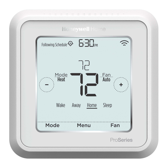
Following Schedule
PM
Mode
Fan
Heat
Auto
Wake Away Home Sleep
Mode
Menu
33-00392EFS-01
Fan
Advertisement
Table of Contents

Related Manuals for Honeywell Home T6 Pro Smart


Summary of Contents for Honeywell Home T6 Pro Smart
- Page 1 Auto Professional Install Wake Away Home Sleep Guide Mode Menu Package Includes: • T6 Pro Smart Thermostat • UWP™ Mounting System • Decorative Cover Plate • Screws and anchors • Thermostat literature Search for local rebates: HoneywellHome.com/Rebates Read before installing Compatibility •...
- Page 2 Optional Decorative Cover Plate installation NOTE: If Optional Cover Plate is not required, see “UWP Mounting System installation” on next page. Use the Optional Cover Plate when you need to cover paint gap from old thermo- stat. There are different cover plates depending on when the thermostat was manufac- tured.
- Page 3 UWP Mounting System installation 1. Open package to find the UWP. See Figure 1. 2. Position the UWP on the wall. Level and mark hole positions. See Figure 2. Drill holes at marked positions, and then lightly tap supplied wall anchors into wall using a hammer.
-
Page 4: Terminal Designations
Wiring UWP Push down on the tabs to put the wires into the inner holes of their corresponding termi nals on the UWP (one wire per terminal) until they are firmly in place. Gently tug on the wires to verify they are secure. If you need to release the wires again, push down the terminal tabs on the sides of the UWP. - Page 5 Setting Slider Tabs Set R Slider Tab, see Figure 1. • Use built-in jumper (R Slider Tab) to differentiate between one or two transformer systems. • If there is only one R wire, and it is connected to the R, Rc, or RH terminal on the old thermostat, set the slider to the up position (1 wire).
-
Page 6: Conventional Systems
Wiring NOTES: 1 Available wiring configurations differ by product models/product numbers. 2 Use 18- to 22- gauge thermostat wire. Shielded cable is not required. 3 Set the R Slider Tab on the UWP to the up position (1 wire) for 1 transformer systems or the down position (2 wires) for 2 transformer systems. - Page 7 Heat pumps systems 1H/1C Heat Pump System 2H/2C Heat Pump System Power Power [R+Rc joined by Slider Tab] [R+Rc joined by Slider Tab] Compressor contactor Compressor contactor (stage 1) 24VAC common 24VAC common O/B Changeover valve O/B Changeover valve Fan relay Fan relay Compressor contactor (stage 2) Heat pump fault input...
-
Page 8: Ventilation Systems
Ventilation systems NOTE: Ventilation is not available on all models. Using U Slider Tab Wired to ERV/HRV whole Wired to fresh air damper house ventilator with internal powered by furnace power supply. transformer. Mounting thermostat Push excess wire back into the wall opening. - Page 9 Installer setup – using the thermostat Setup using the thermostat • After the thermostat has powered up, touch START SETUP on the thermostat. You’ll be asked if you want to perform setup via app. Touch No. Back • Touch to toggle between Installer Set Up (ISU) options.
- Page 10 Installer setup – using the Resideo Pro app Setup using the app Download the Resideo Pro or Honeywell Home app from App Store or Google Play to install and personally invite your customer to connect the installed thermostat at the same time. With the Resideo Pro app, you can personally invite your customer to connect their account.
-
Page 11: Key Features
Key features System status Connection status Time, ISU #, or information information Alert # Cool On, Heat On Status of Wi-Fi Emergency Heat On, Connection: Connected, Recovery, or Auto Disconnected, or Wi-Fi Changeover On. is Off. Schedule information Messaging Heat On Recovery Following Schedule Auto Chg. - Page 12 Select outdoor temperature data source. This ISU automatically defaults to Internet when registered to Honeywell Home app and no wired outdoor sensor is selected. We recommend using a wired outdoor sensor connected to the “S” terminals on the UWP. (See "Wiring" on page 6.)
- Page 13 # ISU ISU Name ISU Options (defaults in bold) Notes Aux Heat Type Electric, Gas/Oil (or Fossil Forced Air) This ISU is displayed only if ISU 200 is set to heat pump AND if ISU 221 Aux/E heat stages = 1. Note: Options of this ISU may vary depending on the model of the thermostat.
- Page 14 # ISU ISU Name ISU Options (defaults in bold) Notes Balance Point Off, 5 °F to 60 °F (in 5 °F increments) or Compressor Lockout requires an outdoor temperature. Set Compressor Lockout to the temperature below (Compressor Lockout) -15.0 °C to 15.5 °C (in 2.5 °C or 3.0 °C increments) which it is inefficient to run the heat pump.
- Page 15 # ISU ISU Name ISU Options (defaults in bold) Notes EM Heat CPH 1 - 12 CPH This ISU is only displayed when Emergency Heat is configured and ISU 253: Aux/E Terminal Control is set to (Heating cycle rate control Aux and E heat Independently. The recommended cycle rate settings are below for each heating equip- Emergency Heat) ment type: Standard Efficiency Gas Forced Air = 5 CPH;...
- Page 16 # ISU ISU Name ISU Options (defaults in bold) Notes Hum Pad Reminder 6, 12 Calendar Months Dehum Filter Reminder 30, 60 Calendar Days 3 - 12 Calendar Months (in 1 month increments) 1000 Vent Type None, ERV/HRV, Passive, Fresh Air Damper None: The thermostat does not control ventilation.
- Page 17 # ISU ISU Name ISU Options (defaults in bold) Notes 1013 Low Outdoor Temp Off, -20 °F to -40 °F (in 5 °F increments) or ISU 130 must be set to Wired or Internet. This ISU is only displayed when ISU 1000 Ventilation Type is set to Vent Lockout -28.0 °C to -4.0 °C (in 2.0 °C increments) ERV / HRV or Fresh Air Damper.
-
Page 18: Performing A System Test
Performing a system test You can test the system setup in ADVANCED MENU under SYSTEM TEST option. Press and hold Menu on the thermostat for 5 seconds to access ADVANCED MENU options. to go to SYSTEM TEST. Touch Touch Select or touch text area. Touch to select system test type. -
Page 19: Troubleshooting
Troubleshooting • Check circuit breaker and reset if necessary. Screen is blank • Make sure power switch at heating and cooling system is on. • Make sure furnace door is closed securely. • Change screen brightness in thermostat Menu. Increase brightness intensity for Screen is difficult inactive backlight of the thermostat screen (max. - Page 20 The Wi-Fi signal has been lost. Please wait for the thermostat to reconnect or select a new Wi-Fi network. Follow steps in the Honeywell Home app Wi-Fi Not Configured Please download the Honeywell Home app and follow the steps to connect thermostat to your Wi-Fi network.
-
Page 21: Specifications
Physical Dimensions in inches (mm) (H x Operating Ambient Temperature W x D) 37 °F to 102 °F (2.8 °C to 38.9 °C) T6 Pro Smart Thermostat (TH6320WF2003): 4-5/64 x 4-5/64 x 1-1/16 (104 x 104 x 27) Shipping Temperature T6 Pro Smart Thermostat (TH6220WF2006): -20 °F to 120 °F (-28.9 °C to 48.9 °C) - Page 22 33-00392EFS—01 M.S. Rev. 03-21 | Printed in United States © 2021 Resideo Technologies, Inc. All rights reserved. The Honeywell Home trademark is used under license from Honeywell International, Inc. This product is manufactured by Resideo Technologies, Inc. and its affiliates.
-
Page 23: Service À La Clientèle
T6 Pro intelligent Thermostat programmable Following Schedule TH6220WF2006 TH6320WF2003 Mode Heat Auto Guide d’installation Wake Away Home Sleep professionnelle Mode Menu La boîte comprend : • Thermostat intelligent T6 Pro • Système de montage UWP™ • Couvercle décoratif • Vis et ancres •... - Page 24 Installation du couvercle décoratif en option REMARQUE : Si la plaque de recouvrement en option n’est pas requise, consultez la section « Installation du système de montage UWP » à la page suivante. Utilisez la plaque de recouvrement en option lorsque vous devez couvrir les cou- pures de peinture de l’ancien thermostat.
- Page 25 Installation du système de montage UWP 1. Ouvrez l’emballage du système UWP. Voir la Figure 1. 2. Placez le système UWP sur le mur. Mettez-le à niveau et marquez les positions des trous. Voir la Figure 2. Percez des trous aux emplacements marqués, puis tapez légèrement sur les ancres murales fournies dans le mur à...
- Page 26 Câblage du système UWP Appuyez sur les languettes pour insérer les fils dans les orifices internes de leurs bornes correspondantes sur le système UWP (un fil par borne) jusqu’à ce qu’ils soient ferme- ment placés. Tirez délicatement sur les fils pour vérifier qu’ils sont bien placés.
- Page 27 Réglages des curseurs Réglez le curseur R, voir la Figure 1. • Utilisez le cavalier intégré (curseur R) pour faire la différence entre les systèmes à un ou deux transformateurs. • S’il n’y a qu’un seul fil R et s’il est connecté...
- Page 28 Câblage REMARQUES : 1 Les configurations de câblage disponibles diffèrent du modèle et de la référence du produit. 2 Utilisez un fil de thermostat de calibre 18 à 22. Câble blindé non requis. 3 Placez le curseur R du système UWP en position haute (1 fil) pour les systèmes à...
- Page 29 Systèmes de thermopompe Système de thermopompe à 1 étage de chauffage/ Système de thermopompe à 2 étages de 1 étage de refroidissement chauffage/2 étages de refroidissement Alimentation Alimentation [R+Rc liés par le curseur] [R+Rc liés par le curseur] Contacteur du compresseur Contacteur du compresseur (étage 1) Borne commune 24 V c.a.
- Page 30 Systèmes de ventilation REMARQUE : La ventilation n’est pas disponible sur tous les modèles. Avec le curseur U Câblé au ventilateur pour Câblé au registre d’air frais toute la maison VRE/VRC alimenté par le transformateur avec alimentation interne. de l’appareil de chauffage. VRE/VRC Re gistre C de l’appareil de chauffa ge...
- Page 31 Configuration de l’installateur avec le thermostat Configuration avec le thermostat • Une fois le thermostat sous tension, appuyez sur START SETUP (Commencer la configuration) sur le thermostat. Il vous sera demandé si vous souhaitez exécuter Back la configuration via l’application. Appuyez sur No (Non).
- Page 32 Configuration de l’installateur avec l’application Resideo Pro Configuration avec l’application Téléchargez l’application Resideo Pro ou Honeywell Home depuis l’App Store ou Google Play pour installer et inviter personnellement votre client à connecter le thermostat installé. Avec l’application Resideo Pro, vous pouvez inviter personnellement votre client à...
-
Page 33: Caractéristiques Principales
Caractéristiques principales Informations d’état du Informations d’état de la Heure, n° d’option de système connexion configuration ou n° Refroidissement, État de la connexion d’alerte chauffage, Chauffage Wi-Fi : Connecté, d’urgence, Récupération, Déconnecté ou Wi-Fi ou Commutation désactivé. automatique. Messages Heat On Recovery Following Schedule Auto Chg. - Page 34 Sélectionnez la source des données de température extérieure. Cette option de configuration passe automatiquement par défaut à Internet lorsque vous êtes enregistré sur l’application Honeywell Home et qu’aucun capteur extérieur câblé n’est sélectionné. Nous vous recommandons d’utiliser un capteur extérieur câblé connecté aux bornes S du système UWP. (Voir « Câblage » à la page 5.) Une température extérieure est nécessaire pour définir les options de configuration de l’installateur (ISU) suivantes :...
- Page 35 N° de Nom de l’option Options de configuration (réglage d’usine en gras) Remarques l’option Type de chauffage Electric (Électrique), Gas/Oil (or Fossil Forced Air) (Gaz/Mazout Cette option ISU ne s’affiche que si ISU 200 est réglé sur Thermopompe ET si ISU 221 Étages Aux/E = 1 ET si ISU 253 est réglé d’urgence (ou air pulsé...
- Page 36 N° de Nom de l’option Options de configuration (réglage d’usine en gras) Remarques l’option Verrouillage du chauffage Off (Arrêt), 5 °F à 65 °F (par incréments de 5 °F) ou Le verrouillage du chauffage auxiliaire requiert une température extérieure. Réglez le verrouillage du chauffage auxiliaire pour auxiliaire (verrouillage optimiser vos factures énergétiques et pour permettre de ne pas activer la source de chauffage auxiliaire plus onéreuse au-delà...
- Page 37 N° de Nom de l’option Options de configuration (réglage d’usine en gras) Remarques l’option Durée de fonctionnement Off (Arrêt), 30, 60, 90 secondes Après la fin de l’appel de chauffage, le thermostat continue d’activer le ventilateur pour la durée sélectionnée pour améliorer l’ef- étendue du ventilateur en 2, 3, 4, 5, 6, 7, 8, 9, 10, 11, 12, 13, 14, 15 minutes ficacité.
- Page 38 N° de Nom de l’option Options de configuration (réglage d’usine en gras) Remarques l’option 1000 Type de ventilation None (Aucune), ERV/HRV (VRC/VRE), Passive, Fresh Air Damper Aucune : Le thermostat ne contrôle pas la ventilation. (Registre d’air frais) VRC/VRE : Le thermostat contrôle un ventilateur de récupération de chaleur ou un ventilateur de récupération d’énergie pour la ventilation.
- Page 39 N° de Nom de l’option Options de configuration (réglage d’usine en gras) Remarques l’option 1015 Verrouillage de la venti- Off, 65 °F à 85 °F (par incréments de 5 °F) ou L’ISU 130 doit être réglé sur Internet. Cette option ISU ne s’affiche que lorsque ISU 1000 Type de ventilation est réglée sur VRC/ lation en point de rosée VRE ou Registre d’air frais.
Need help?
Do you have a question about the T6 Pro Smart and is the answer not in the manual?
Questions and answers